Assembly instructions for Aspen Upholstered Ottoman TV Bed by Time4Sleep.
Product Information
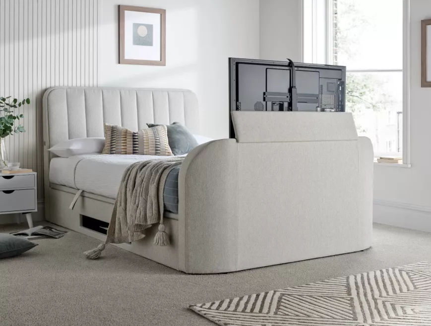
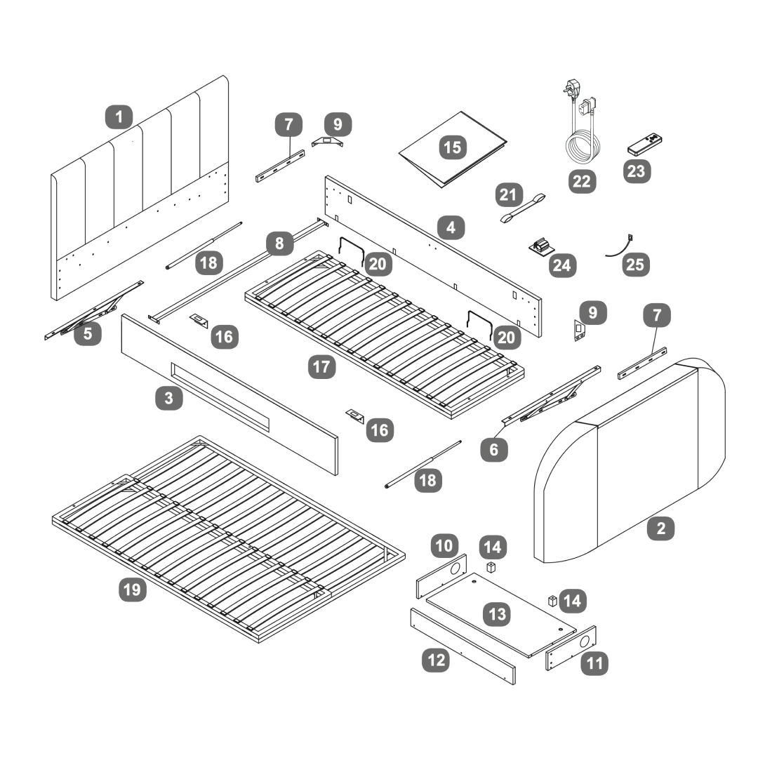
Aspen Upholstered Ottoman TV Bed
The Aspen Surround Sound TV bed frame is a brand new TV bed featuring a built-in 2.1 Soundbar, USB-C charging and headphone jack for an enhanced experience. Kick back and relax in comfort, whilst watching TV or listening to your favourite music, from the comfort of your bed.
Beautifully upholstered, this model features a luxurious padded, generously proportioned headboard that is sure to provide a real focal point in any bedroom. This bed's ultra slimline footboard discreetly houses a TV mechanism with an automatic cut-off feature, ensuring the TV powers off when retracted. A convenient shelf within the bed’s base provides storage for DVD players and gaming consoles.
The platform ottoman base can be simply raised and lowered with the assistance of the gas lift mechanism to reveal a large storage which is approximately 32cm in depth. The space saving design means the mattress sits on top of the sleeping platform which sits on the side rails, this helps to minimise the footprint of the bed making it an ideal option for smaller rooms.
As a guide this model will accommodate an LED flat screen TV upto 43".
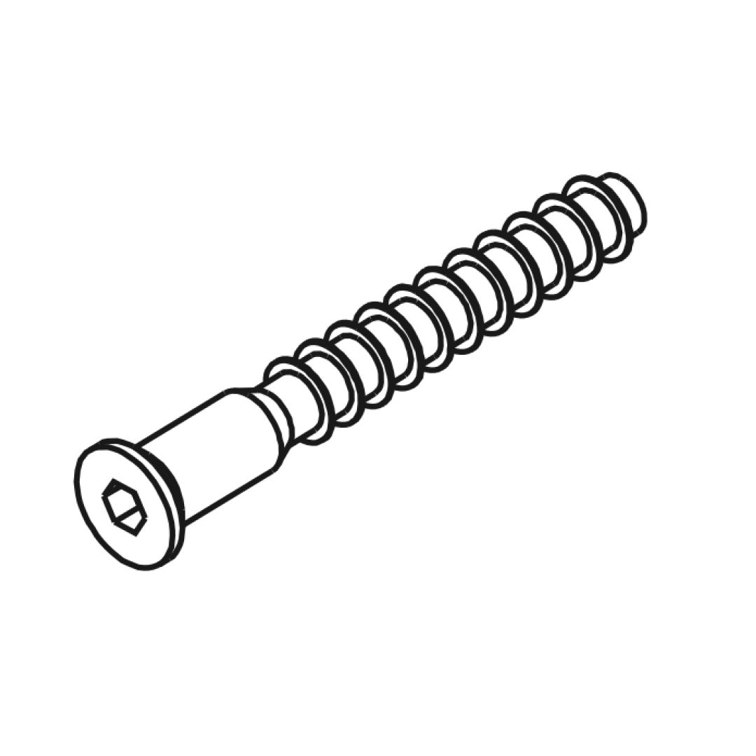
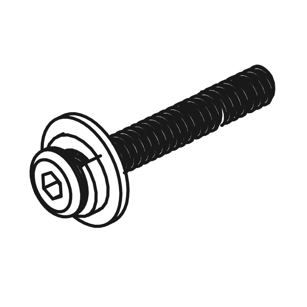
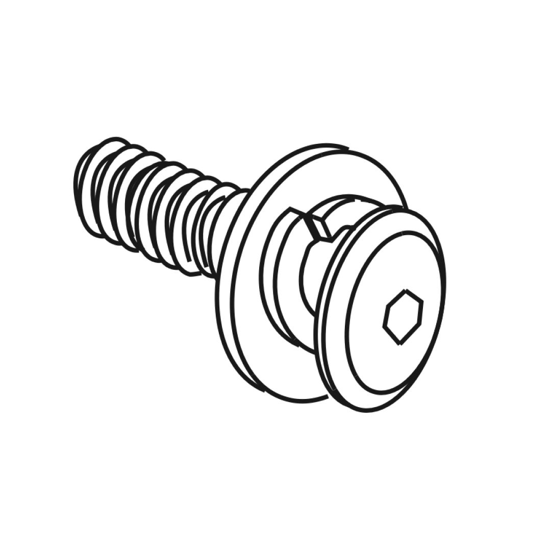
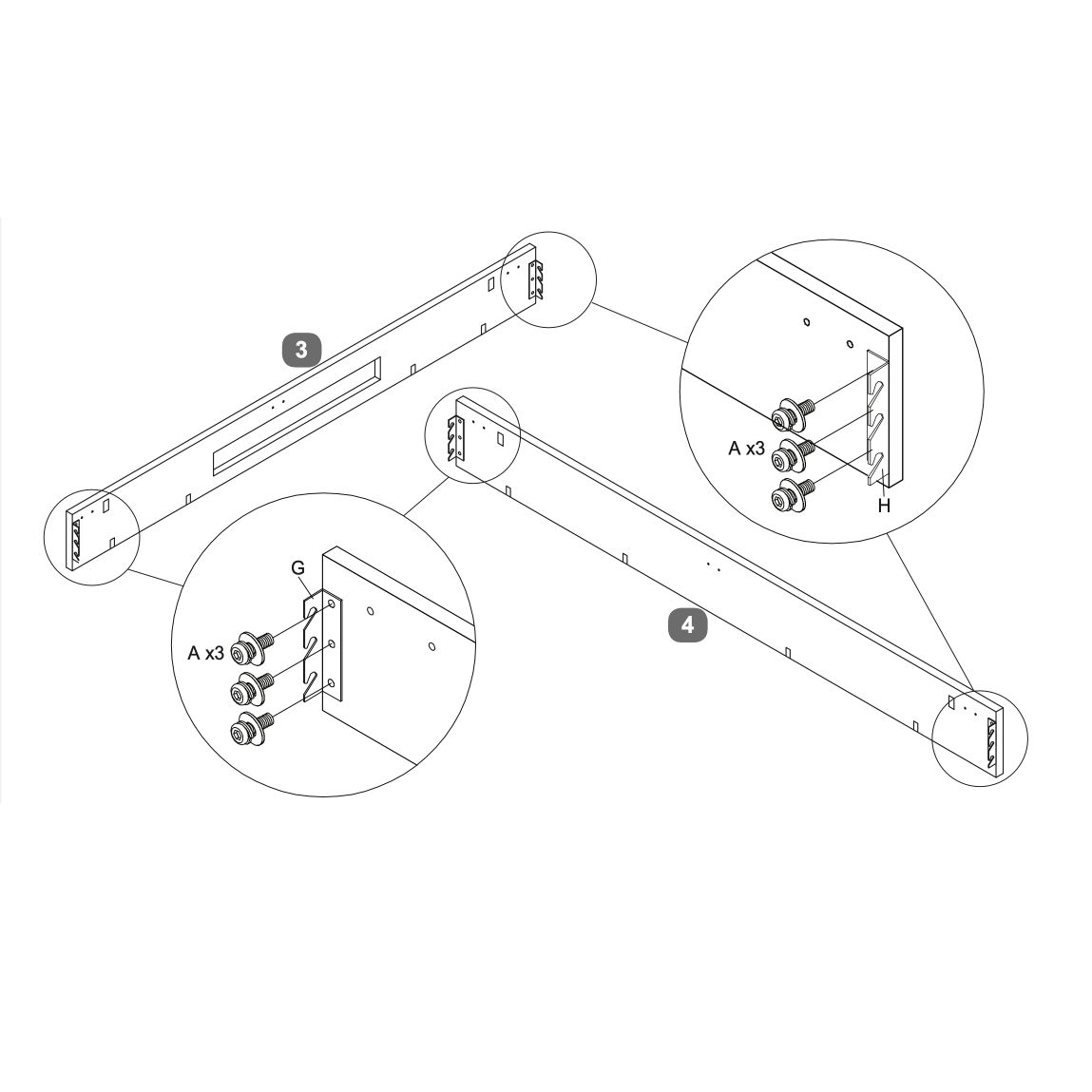
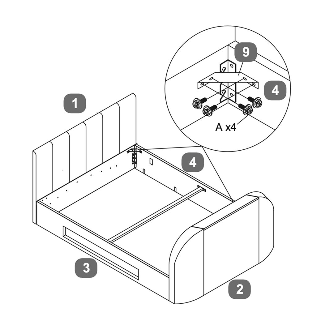
1. Align the side rail with the headboard and footboard. Ensure the pre-drilled holes are properly aligned. 2. Insert three bolts (A) through the holes in the side rail into the corresponding holes in the headboard and footboard. 3. Secure each bolt with a washer (G) and nut (H). Tighten them to ensure a firm connection. 4. Repeat the process for the other side rail, ensuring both are securely attached and the frame is squared.
Ensure all connections are tight and the frame is stable before proceeding with the next steps of the assembly.
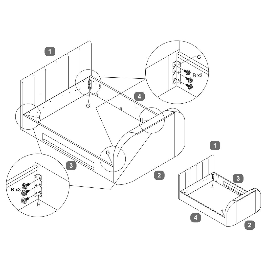
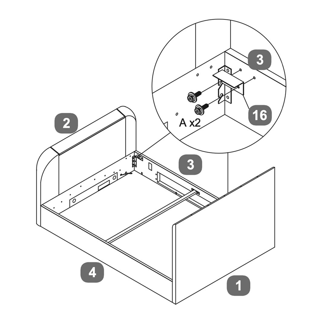
2. Headboard and footboard
1. Position the side rails to connect with the headboard and footboard. 2. Use bolts (B) and washers (G) to secure the side rails to the headboard and footboard. Ensure all connections are tight. 3. Ensure the bed frame is squared by attaching the cross bar securely. 4. Verify that all components are properly aligned and securely fastened.
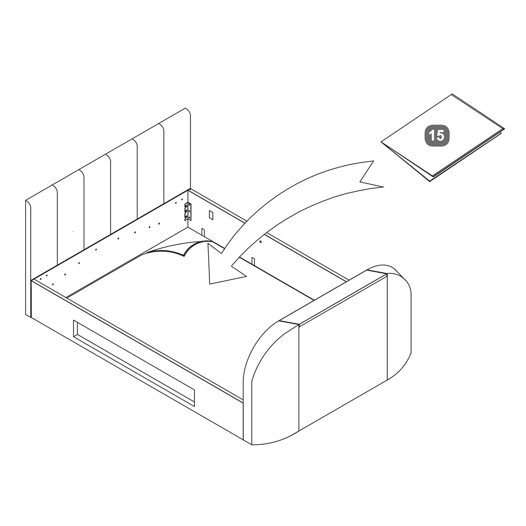
3. Fabric Base Cover
1. Position the fabric base cover (part 15) inside the bed frame. 2. Ensure it is aligned properly with the edges of the frame. 3. Secure the fabric base cover in place as per the assembly instructions provided with the bed.
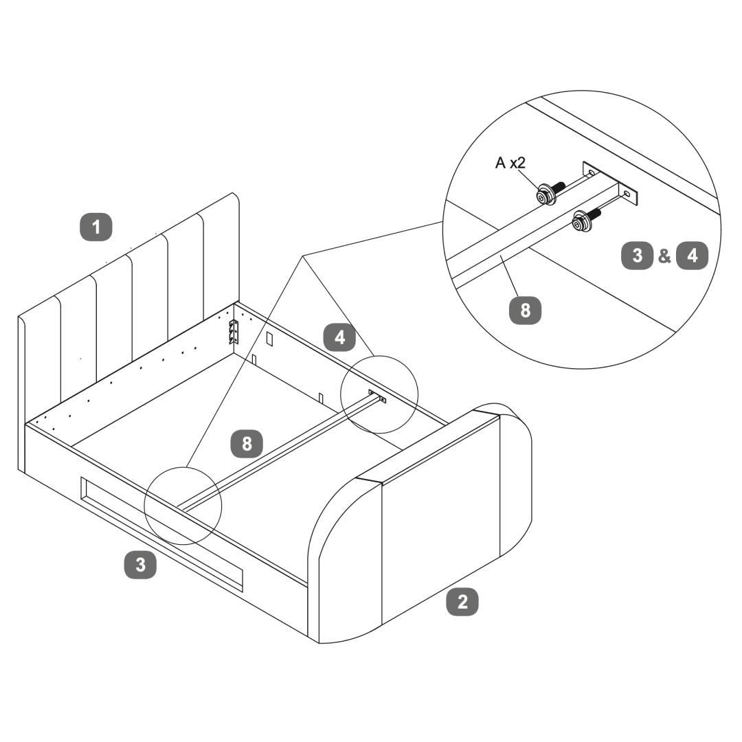
4. Cross Bar
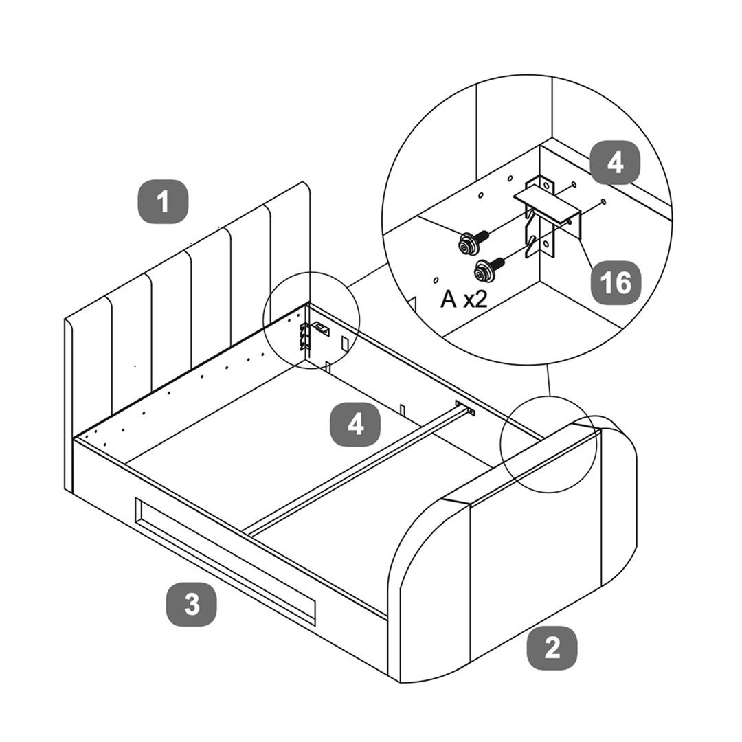
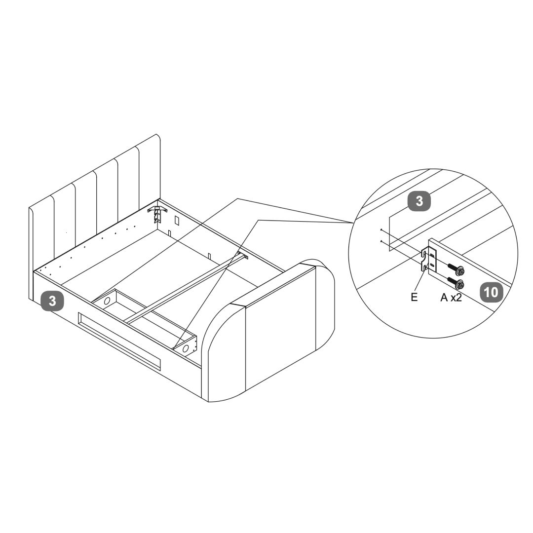
1. Position the side rails (3) to connect with the headboard (1) and footboard (2). 2. Use bolts, washers, and nuts (A x2) to secure the side rails to the headboard and footboard. Ensure the frame is squared and stable. 3. Position the cross bar (8) across the bed frame and secure it using the provided hardware. Ensure it is properly aligned and tightened.
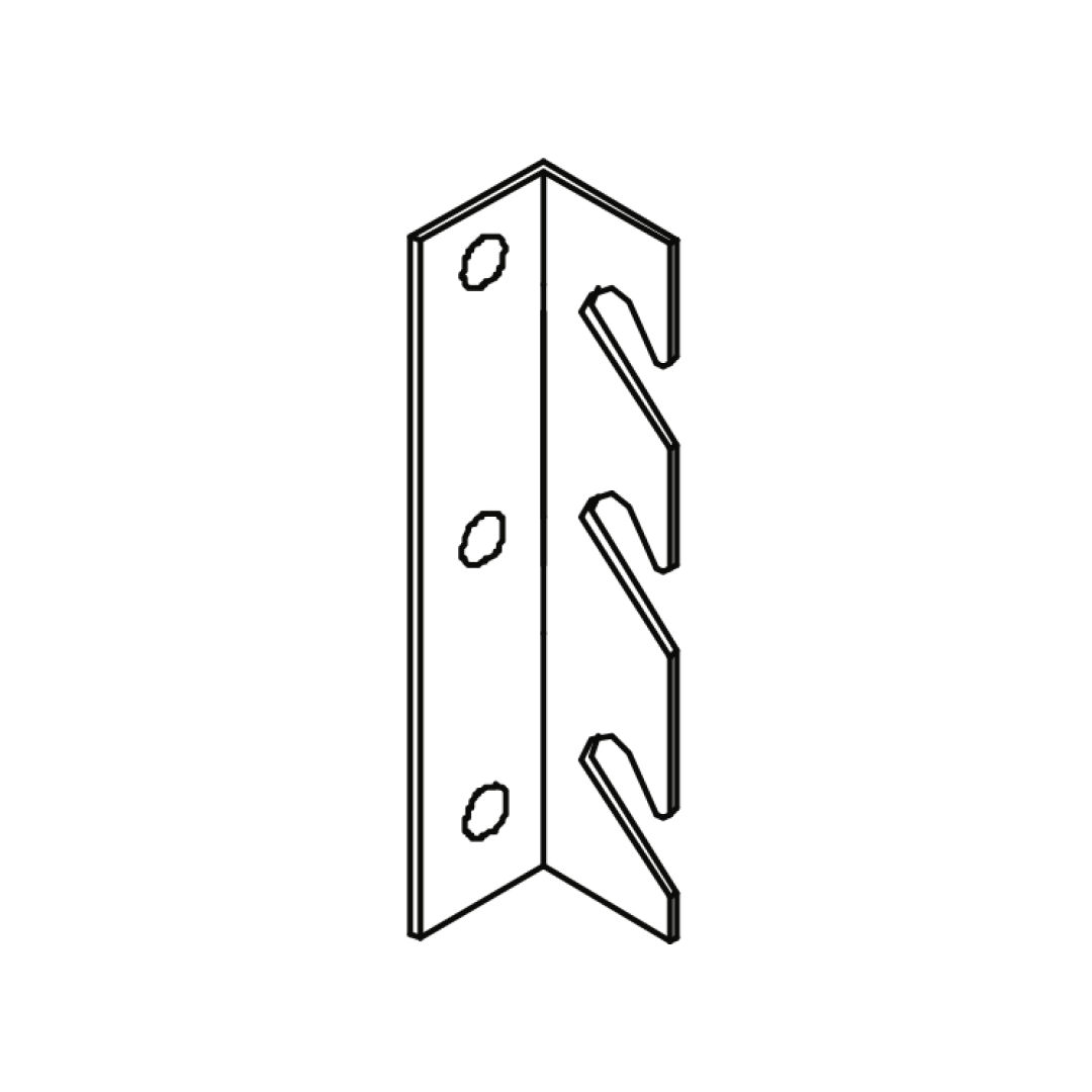
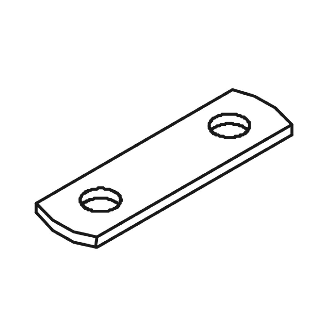
5. Corner Brackets - Open from Left
If you want to lift up your bed from the left:
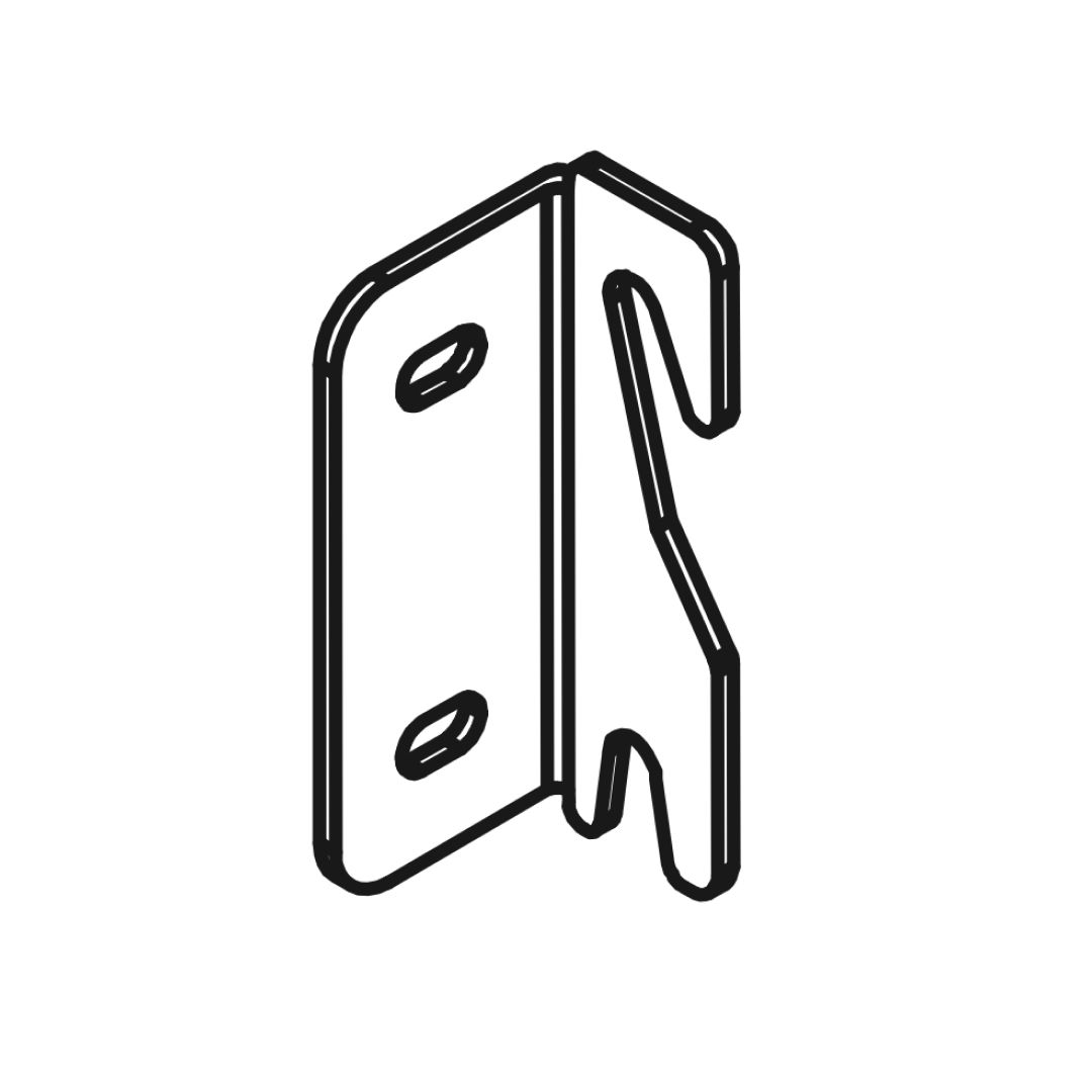
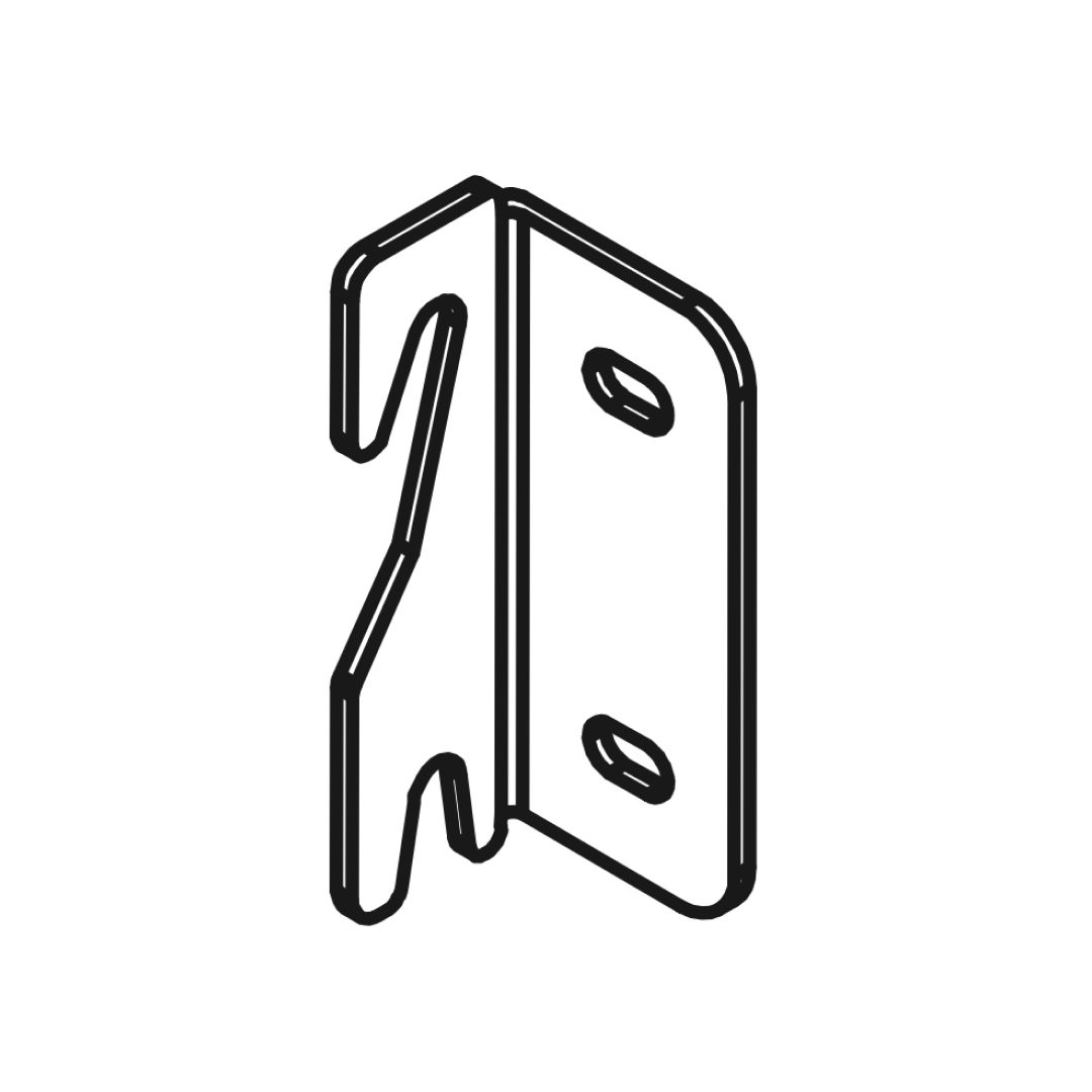
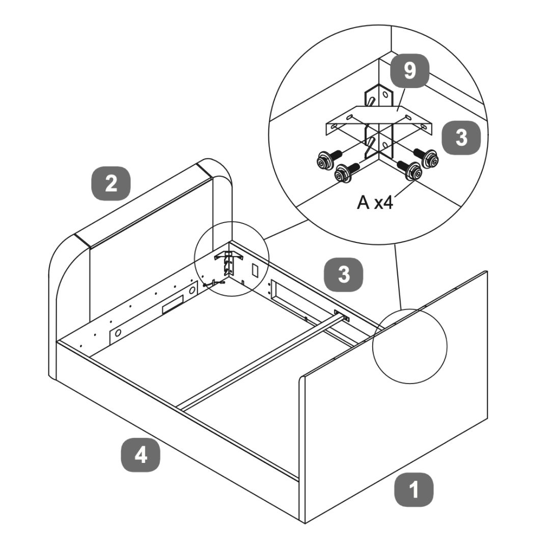
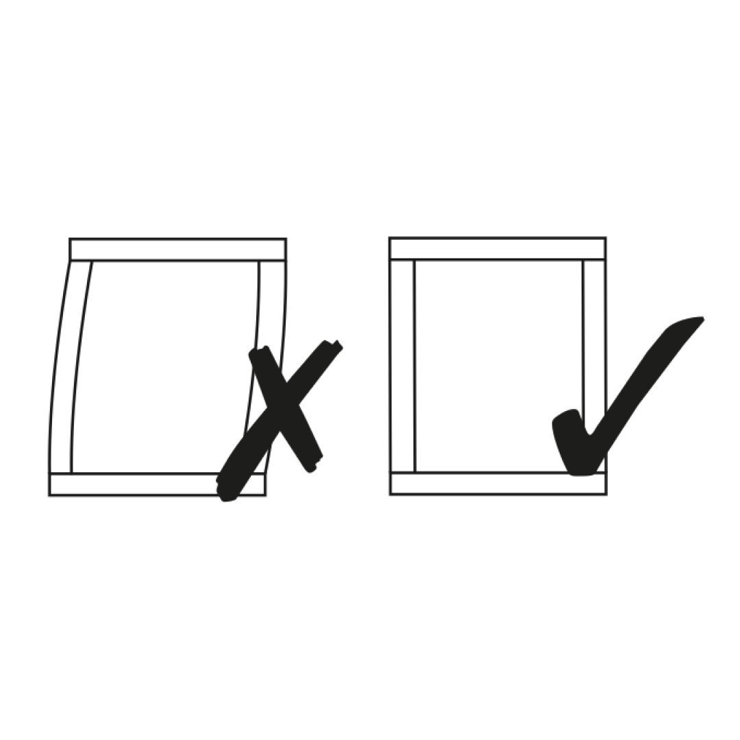
1. Secure the ‘L’ Shape Bracket (16) in the right corners sides using the provided bolt sets (A x2). 2. Attach the Angled Corner Brackets (9) in the left corners sides using the provided bolt sets (A x4). 3. Verify that the frame is stable and properly aligned. Ensure all parts are securely attached. 4. Check that the bed is squared, as shown in the final diagram, to ensure proper assembly.
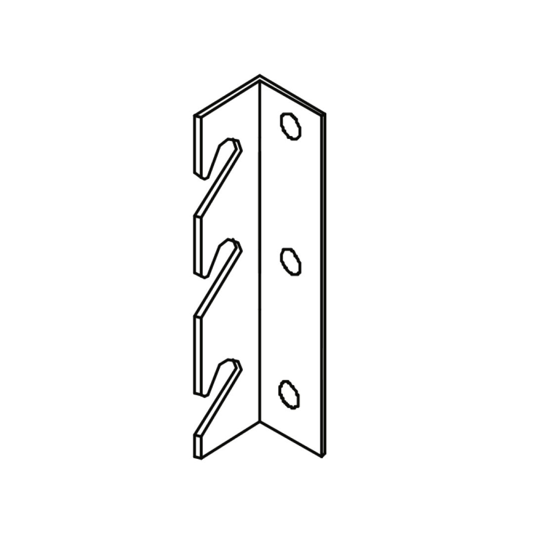
6. Corner Brackets - Open from Right
If you want to lift up your bed from the right:
1. Attach the Angled Corner Brackets (9) in the right corners sides using the provided bolt sets (A x4). 2. Secure the ‘L’ Shape Bracket (16) in the left corners sides using the provided bolt sets (A x2). 3. Verify that the frame is stable and properly aligned. Ensure all parts are securely attached. 4. Check that the bed is squared, as shown in the final diagram, to ensure proper assembly.
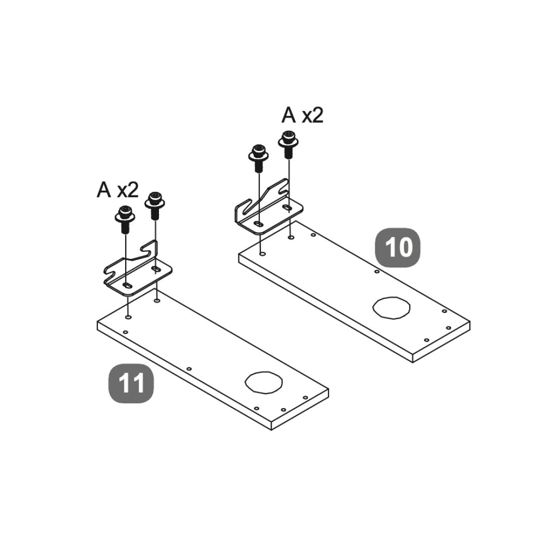
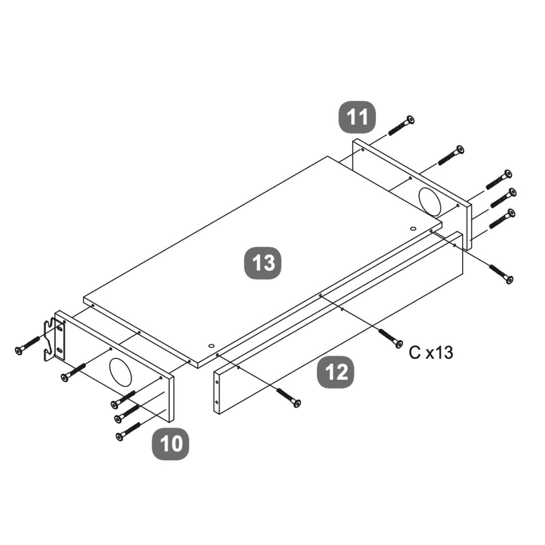
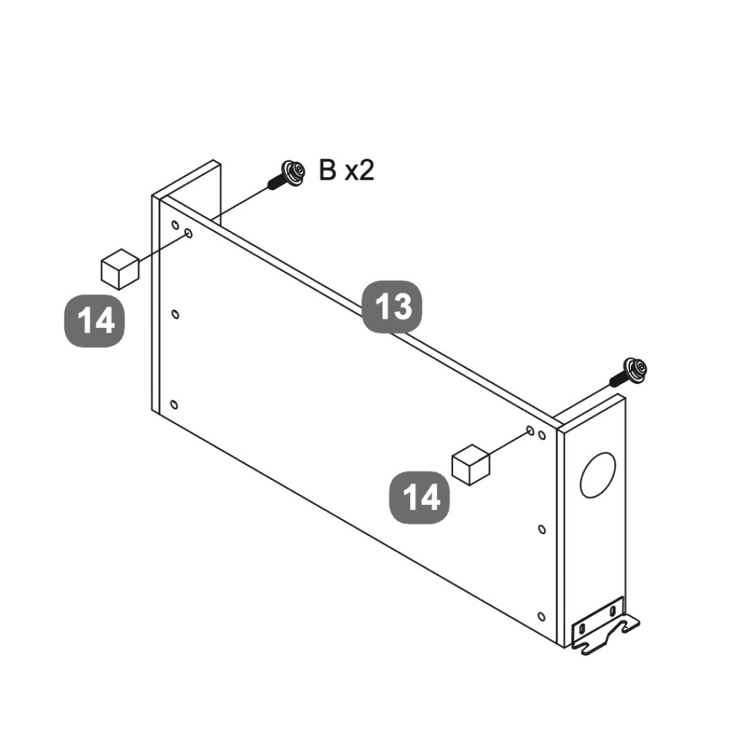
7. Media Tray
1. Secure two brackets (A) to each of the side panels (10 and 11) using the provided screws and nuts. 2. Connect panels 10 and 11 to the side panel 12 using screws (C x13). 3. Attach the base panel 13 to the assembled frame, aligning it with the pre-drilled holes and securing it with screws. 4. Attach support legs (14) to the panel 13 using screws (B x2). 5. Ensure all components are securely fastened and aligned properly before proceeding with further assembly or installation.
8. Attach Media Tray
1. Secure the media tray to the corresponding side using bolts (A) provided 2. Ensure all components are tightly fastened and properly aligned
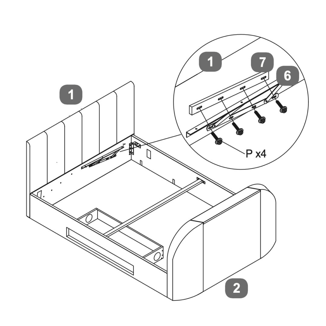
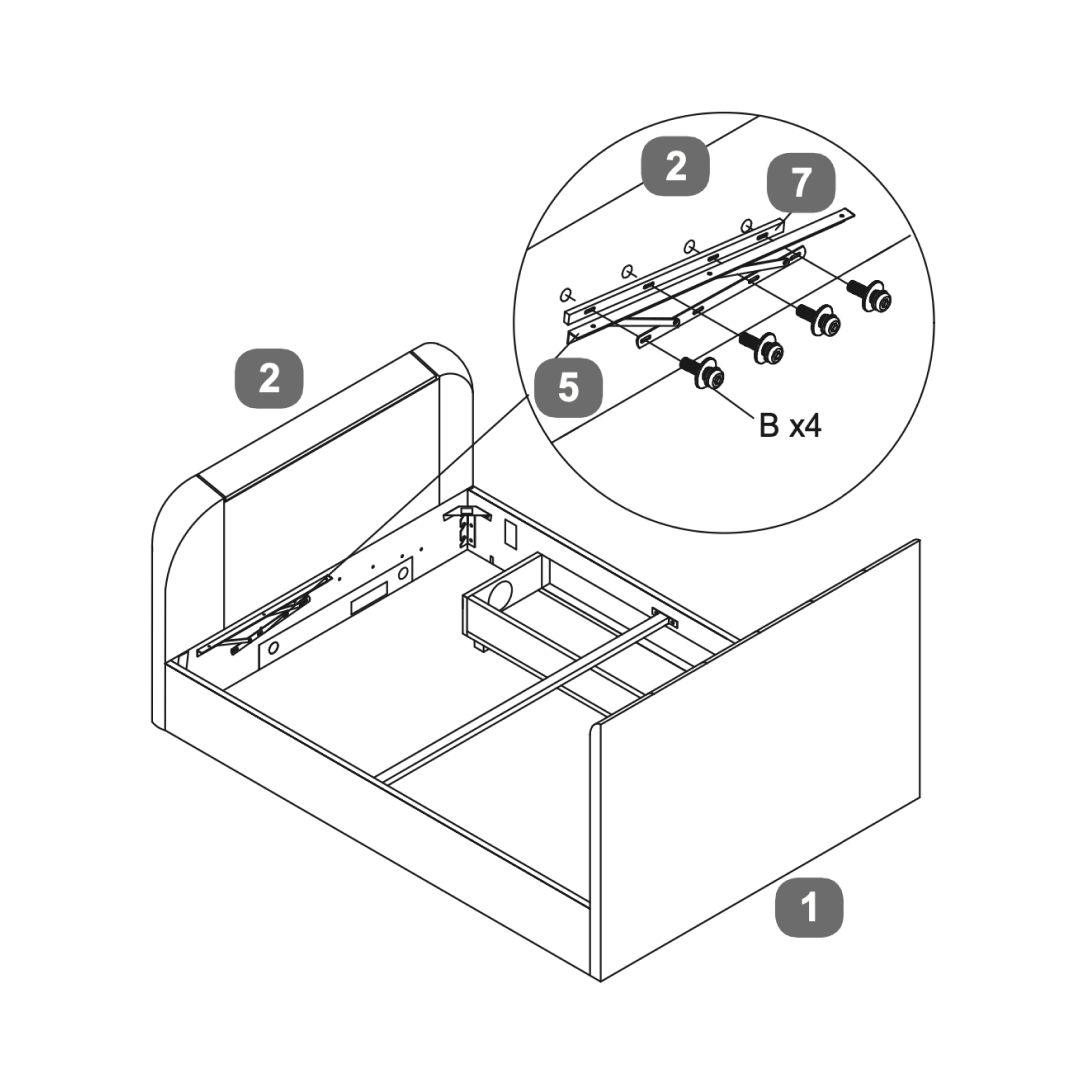
9. Lift Mechanism - Open from Left
To open the bed from the left:
1. Attach the lift mechanism RH (6) to the right side of the headboard using P bolt sets. 2. Attach the lift mechanism LH (6) to the left side of the footboard using B bolt sets. 3. Ensure all components are securely fastened.
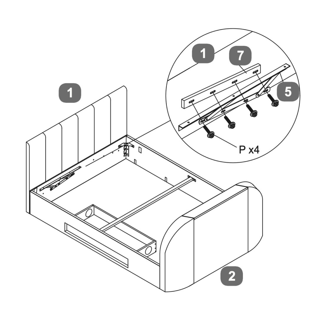
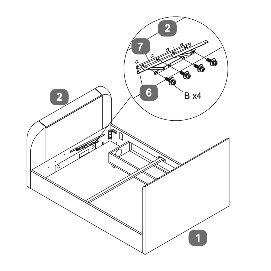
10. Lift Mechanism - Open from Right
To open the bed from the right:
1. Attach the lift mechanism LH (6) to the left side of the heatboard using P bolt sets. 2. Attach the lift mechanism RH (6) to the right side of the footboard using B bolt sets. 3. Ensure all components are securely fastened.
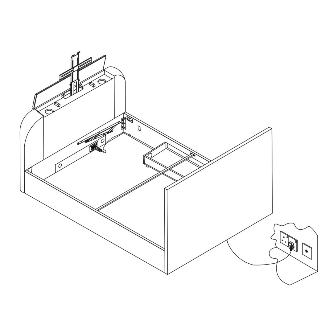
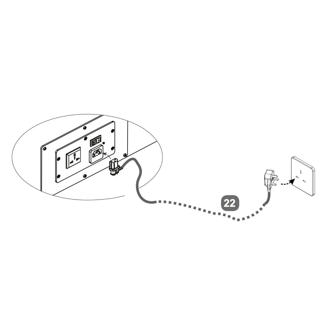
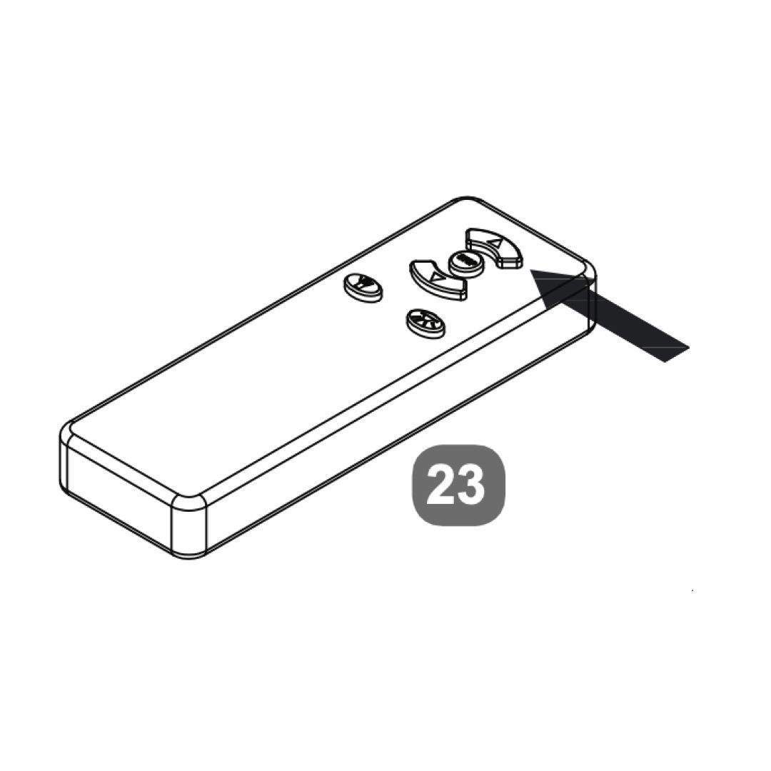
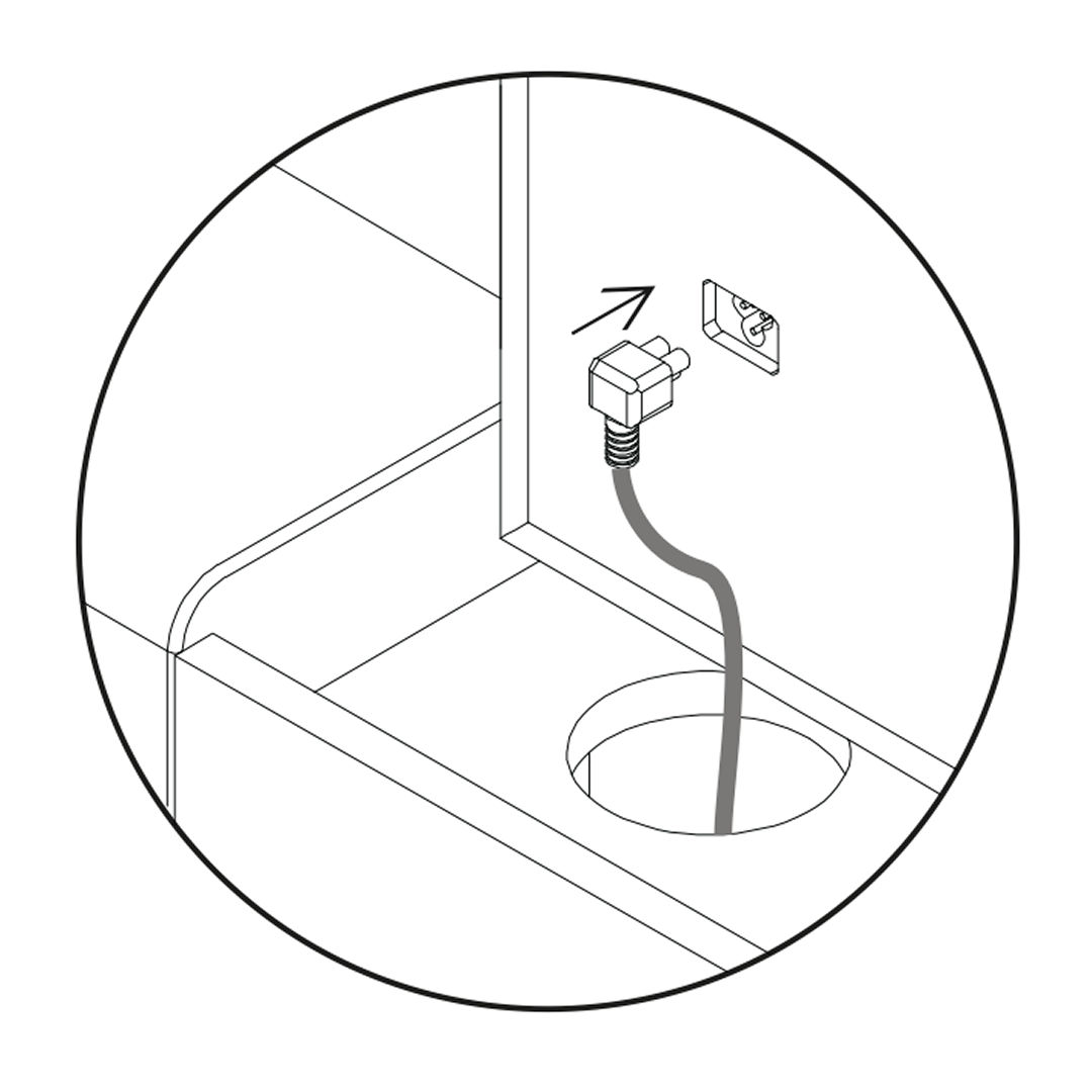
11. TV Lift Power Cable
1. Attach the power cable to the TV lift mechanism at the headboard. 2. Connect the power cable to the nearest electrical outlet - for safety, this must be an earthed supply. 3. Use the handheld remote control to operate the TV lift. Press the “UP” button to raise the TV lift.
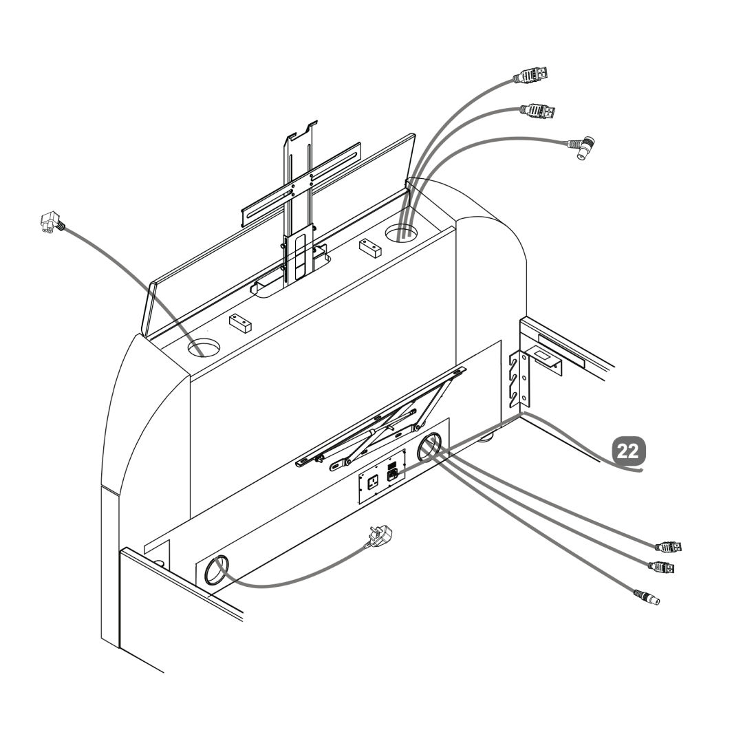
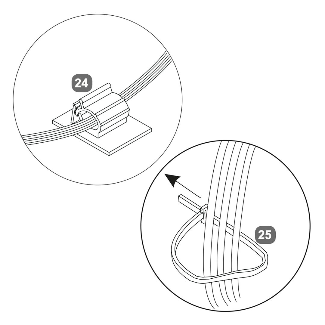
12. Media Cables
Pass the TV power and media cables through the side holes of the footboard.
For illustration only, cables should be fitted to suit the positions of the ports in your own TV.
Media cables are not supplied.
Tip:
Before fitting the television, push any leads through each duct from the top.
Choose the best side to use depending on where the connection ports are on back of your tv. Never cross cables from one side to the other.
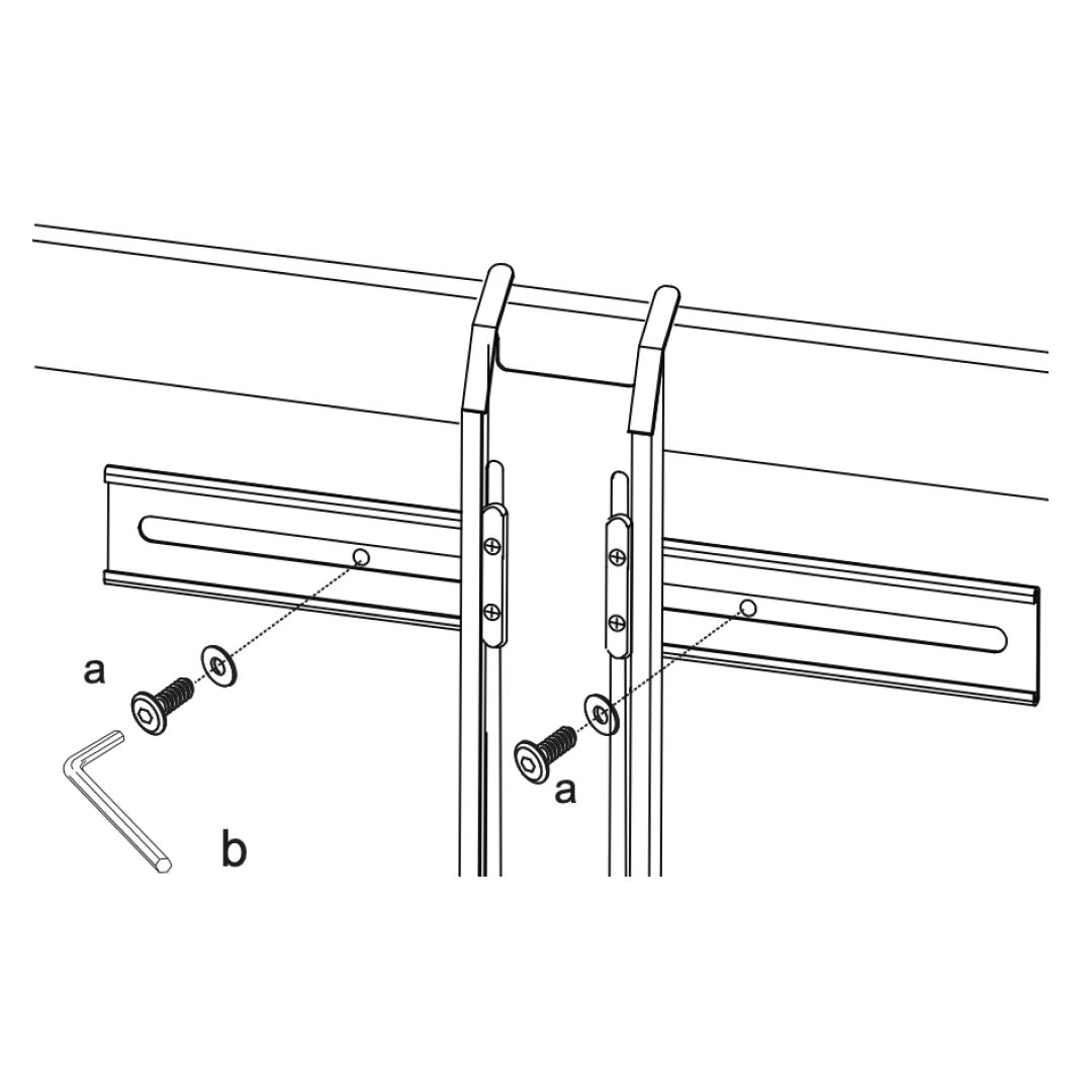
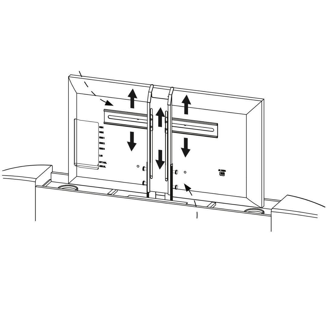
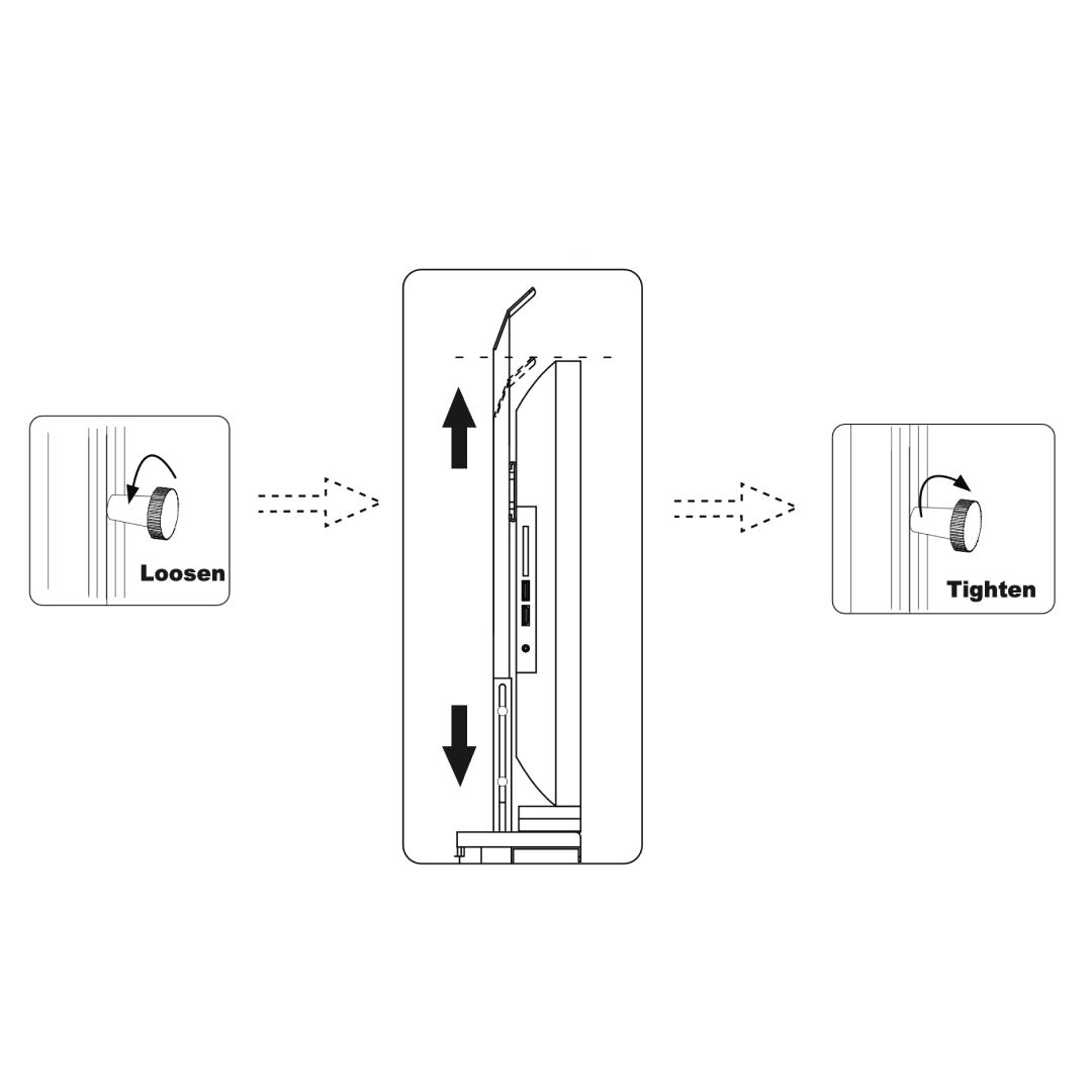
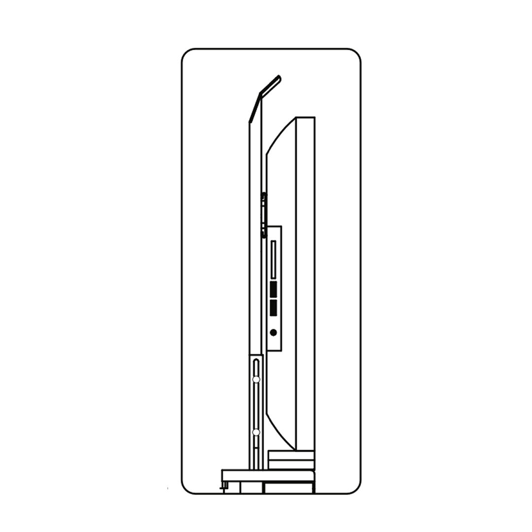
13. TV Mechanism
1. Secure metal brackets to the lift mechanism with screws (a). 2. Align and secure the TV to the brackets. 3. Loosen knobs, set height, then tighten. 4. Ensure smooth movement, adjust if needed.
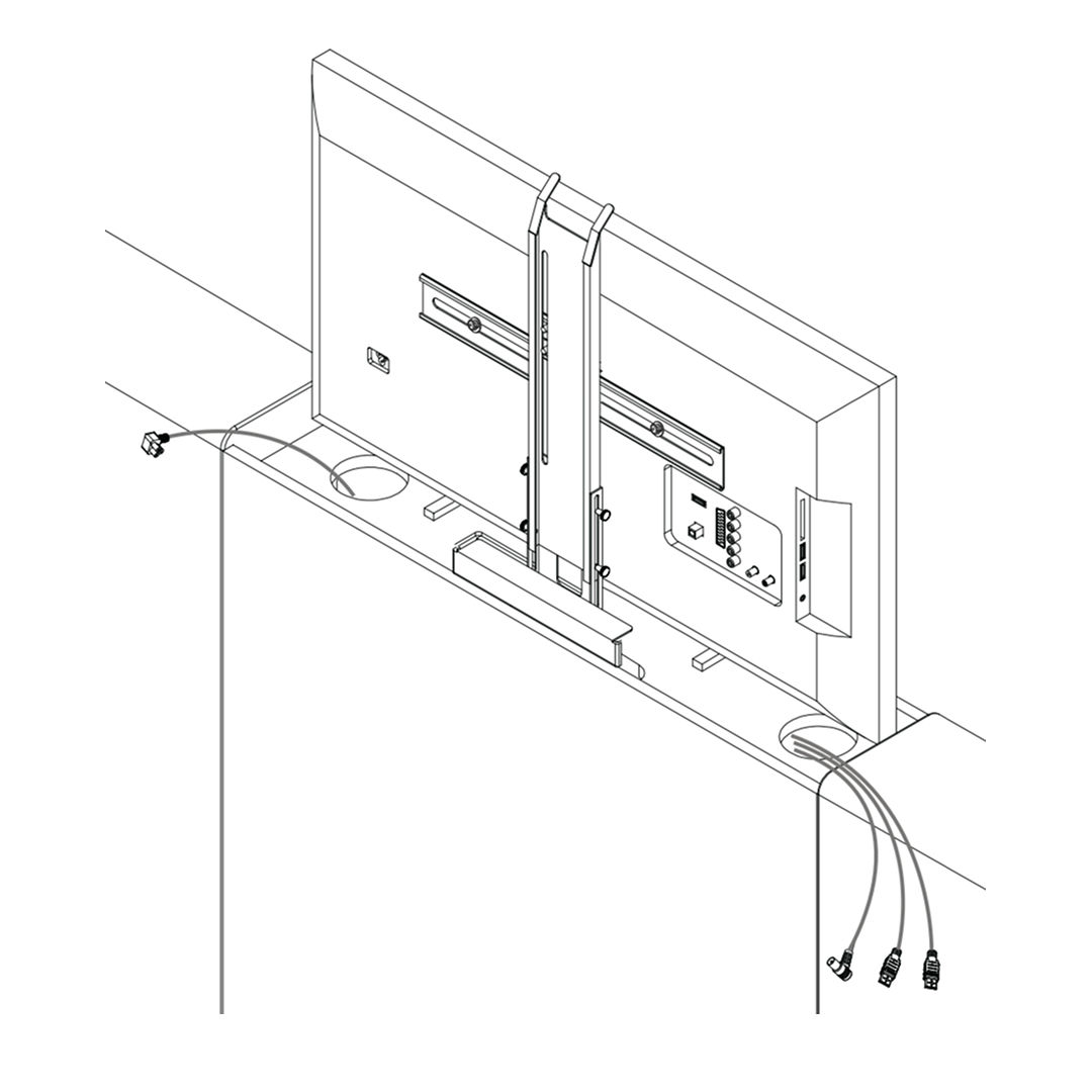
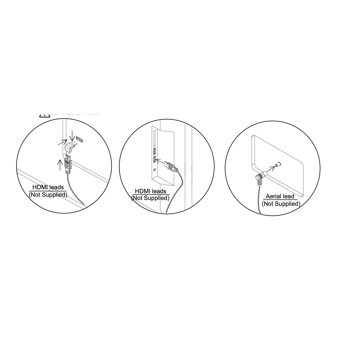
14. TV cables
1. Insert the power cable into the designated socket on the TV lift mechanism. Ensure the connection is secure. 2. Attach HDMI leads to the TV's HDMI ports. Note that HDMI leads are not supplied. 3. Connect the aerial lead to the TV's aerial input. The aerial lead is also not supplied. 4. Use the provided cable clips to secure and organize the cables. Ensure they are neatly arranged to prevent tangling or obstruction.
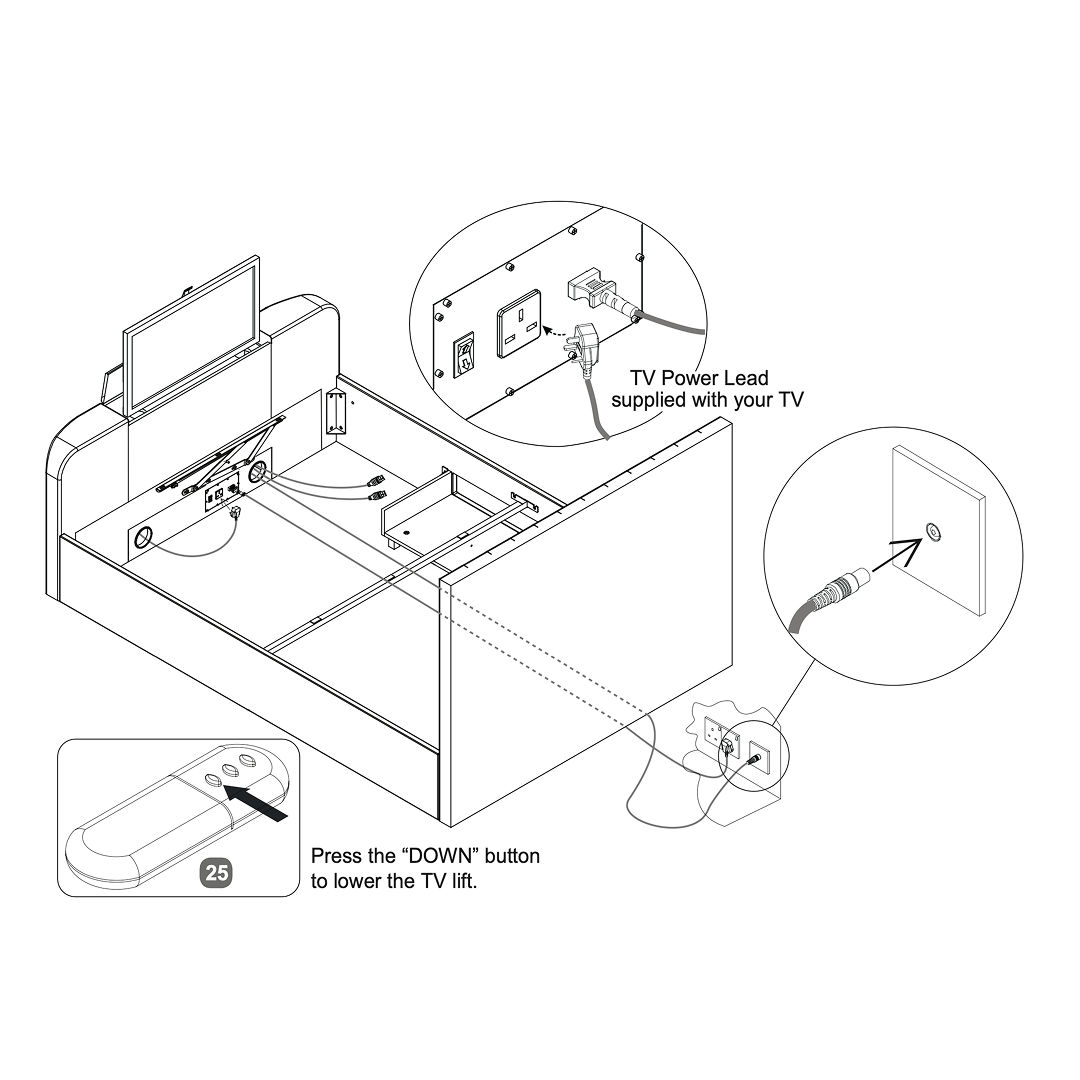
15. Connect the cables
1. Connect the TV power lead supplied with your TV to the power outlet. 2. Ensure the media cables are properly connected through the designated slots in the footboard. 3. Use the remote control to press the "DOWN" button, lowering the TV lift mechanism into the bed frame.
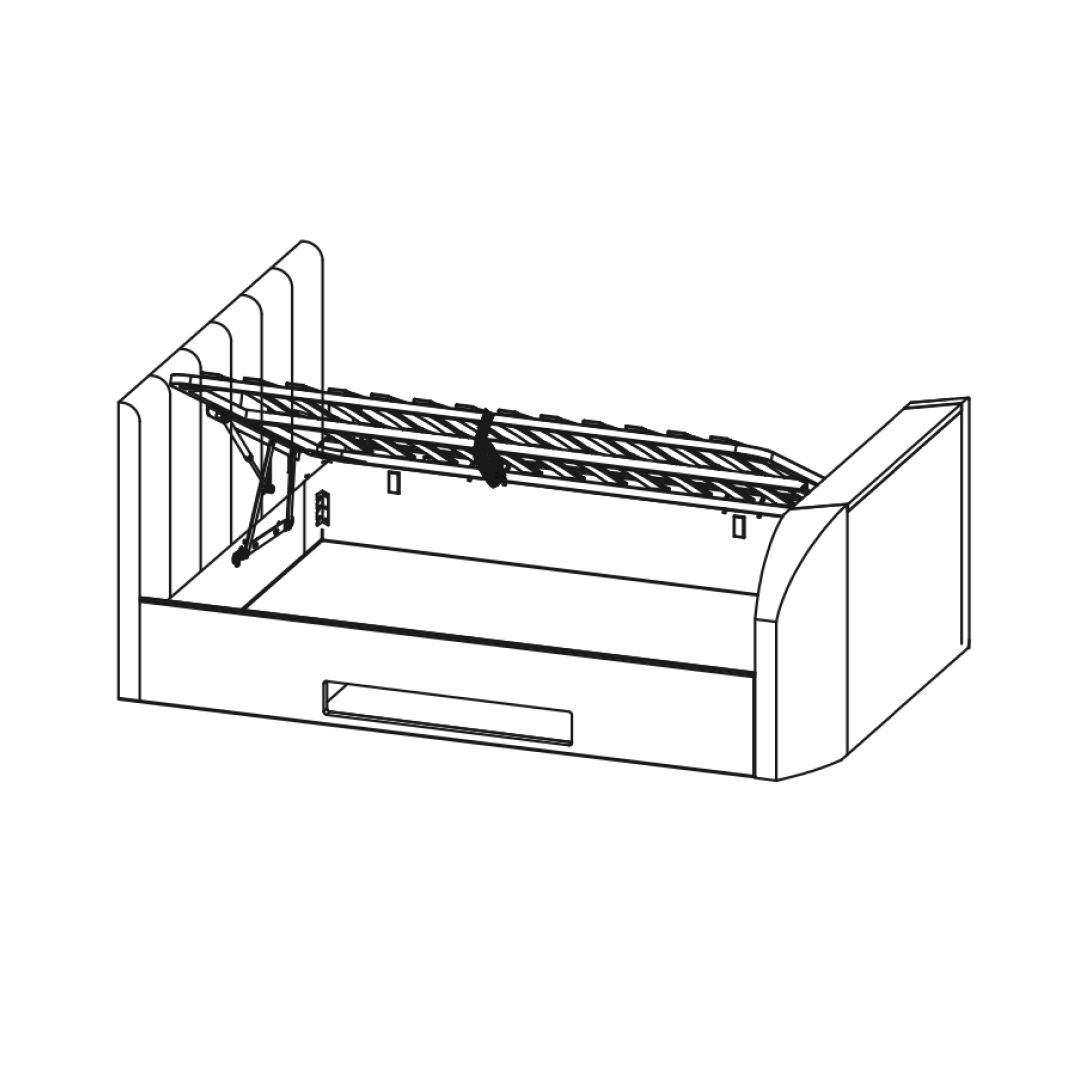
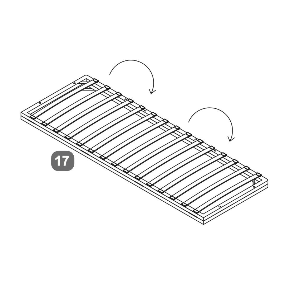
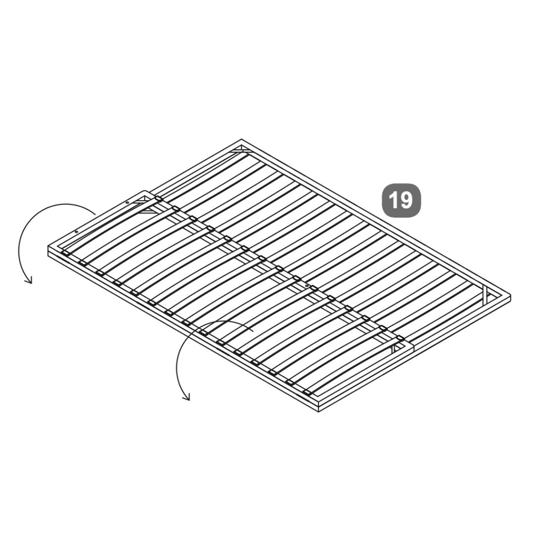
16. Slatted Base
1. Begin by laying out the slatted base as shown in the images. 2. Use the provided bolts and washers (labeled as A) to secure the slats to the frame. Insert two bolts on each side as indicated in the images. 3. Insert the support bars into the designated slots on the slatted base. 4. Verify that all components are tightly secured and aligned.
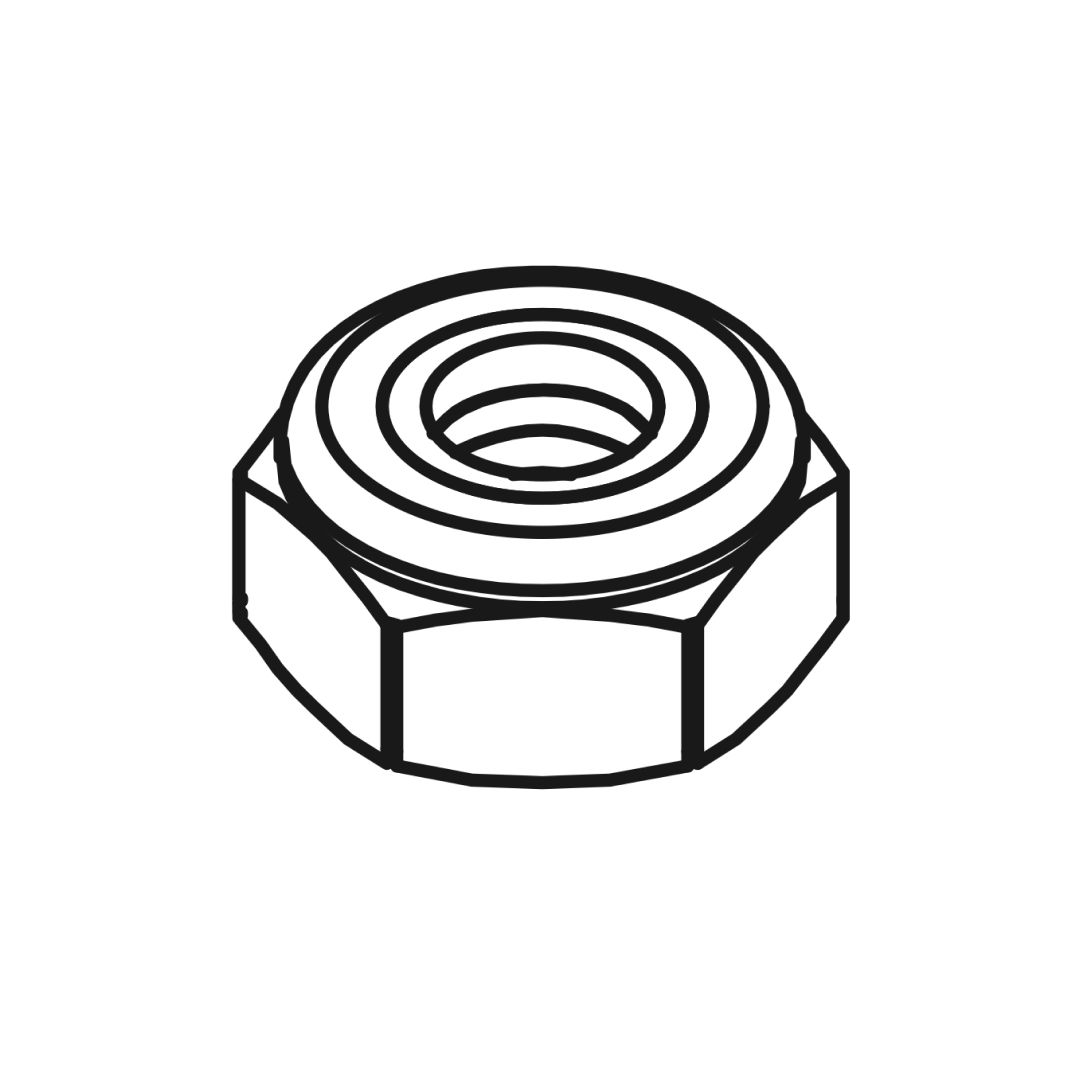
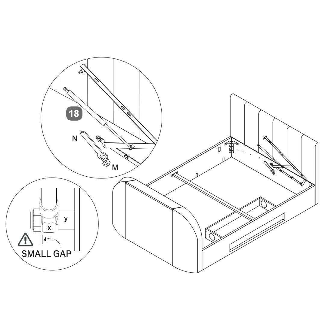
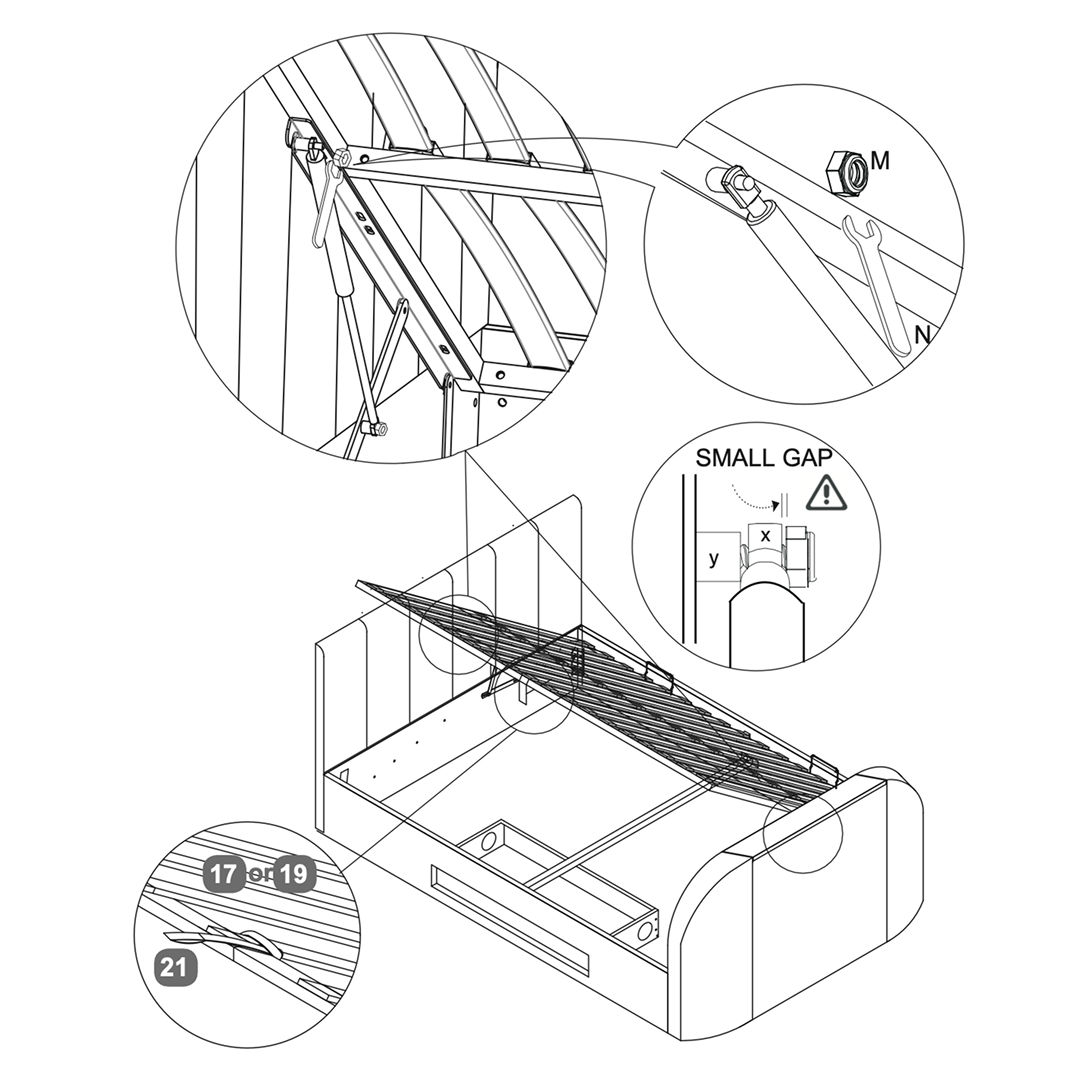
17. Slide gas-lift piston stem
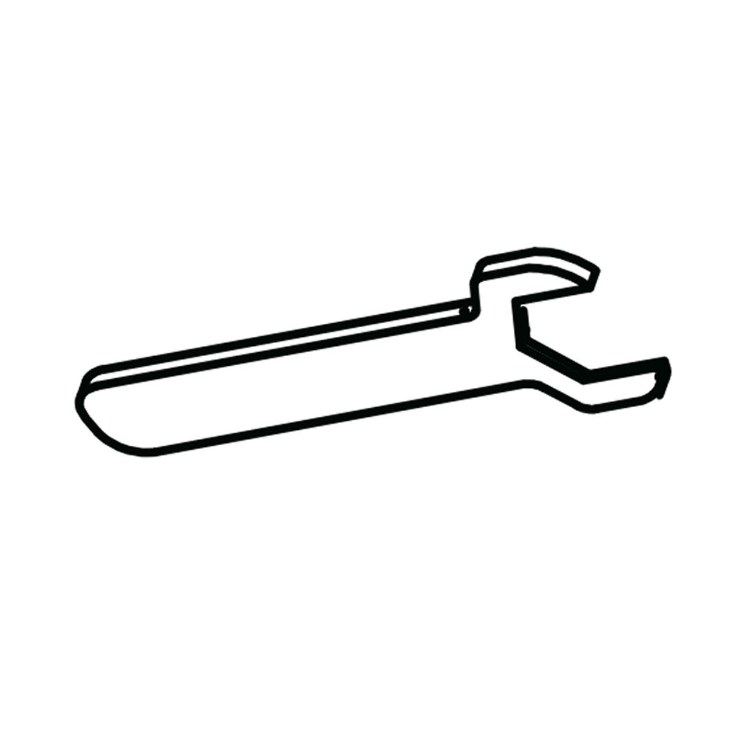
1. Slide gas-lift piston stem (x) onto the axle (y) then fit the flange lock-nut (M). 2. Tighten nut with spanner (N)- do not over-tighten
A small gap must be left so stem can move freely
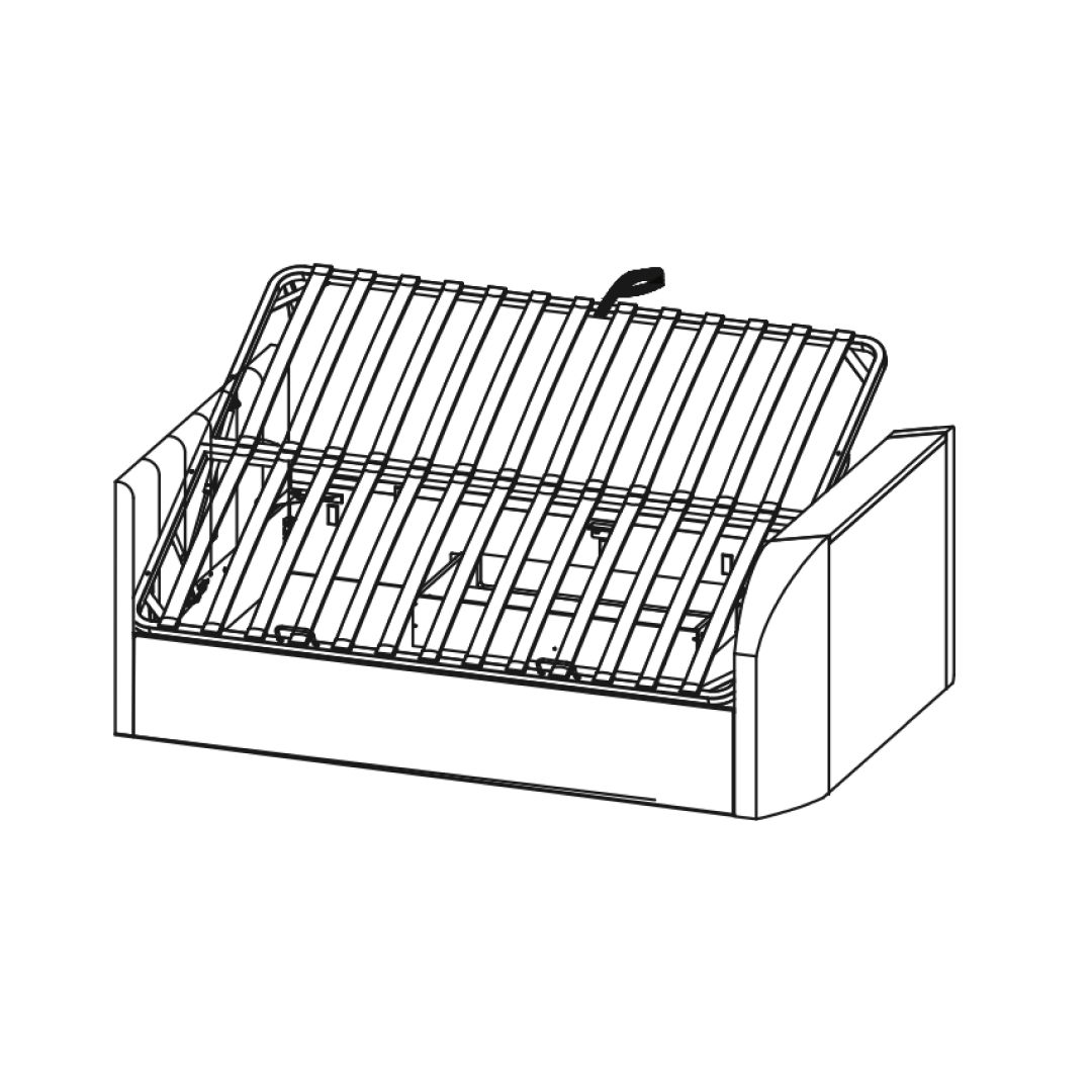
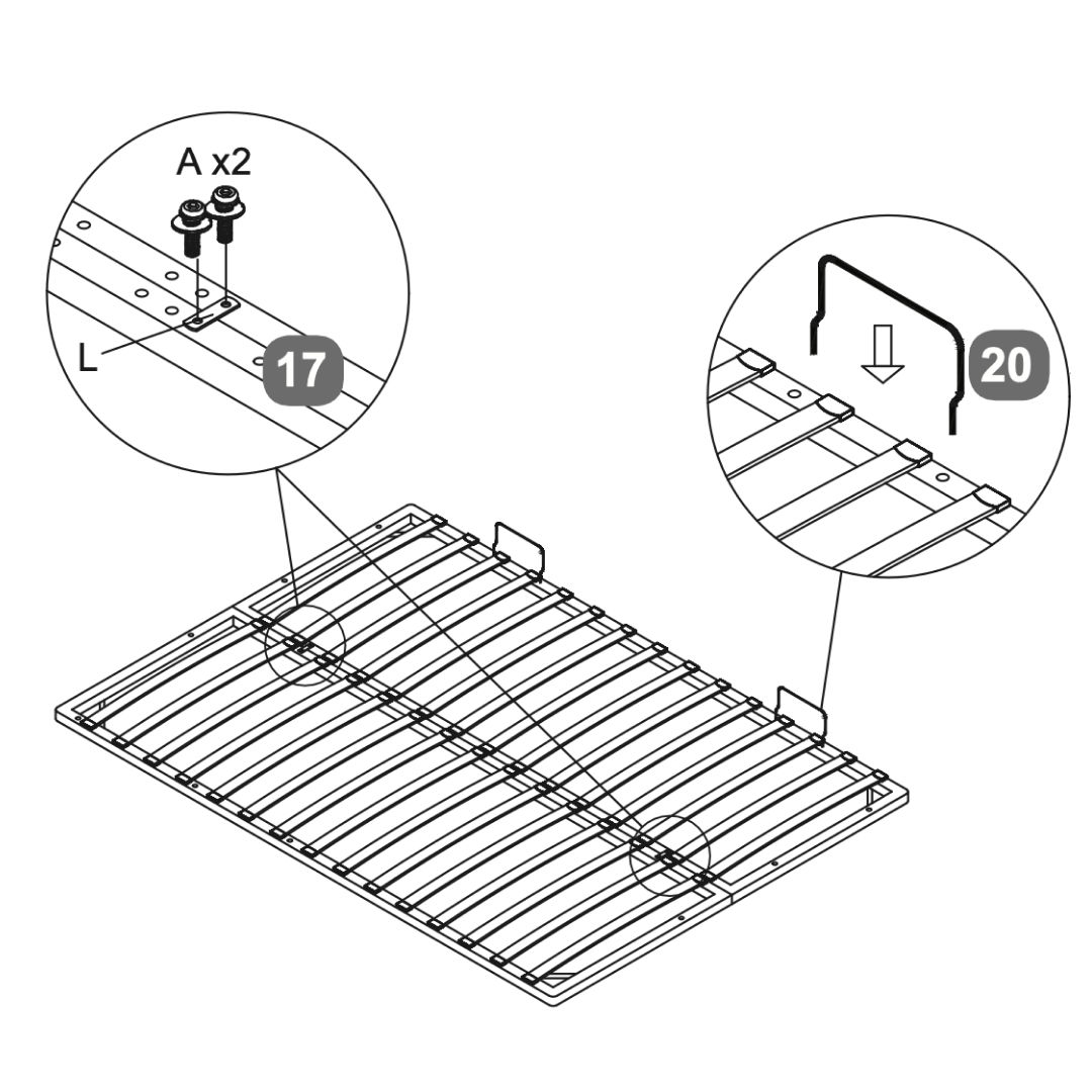
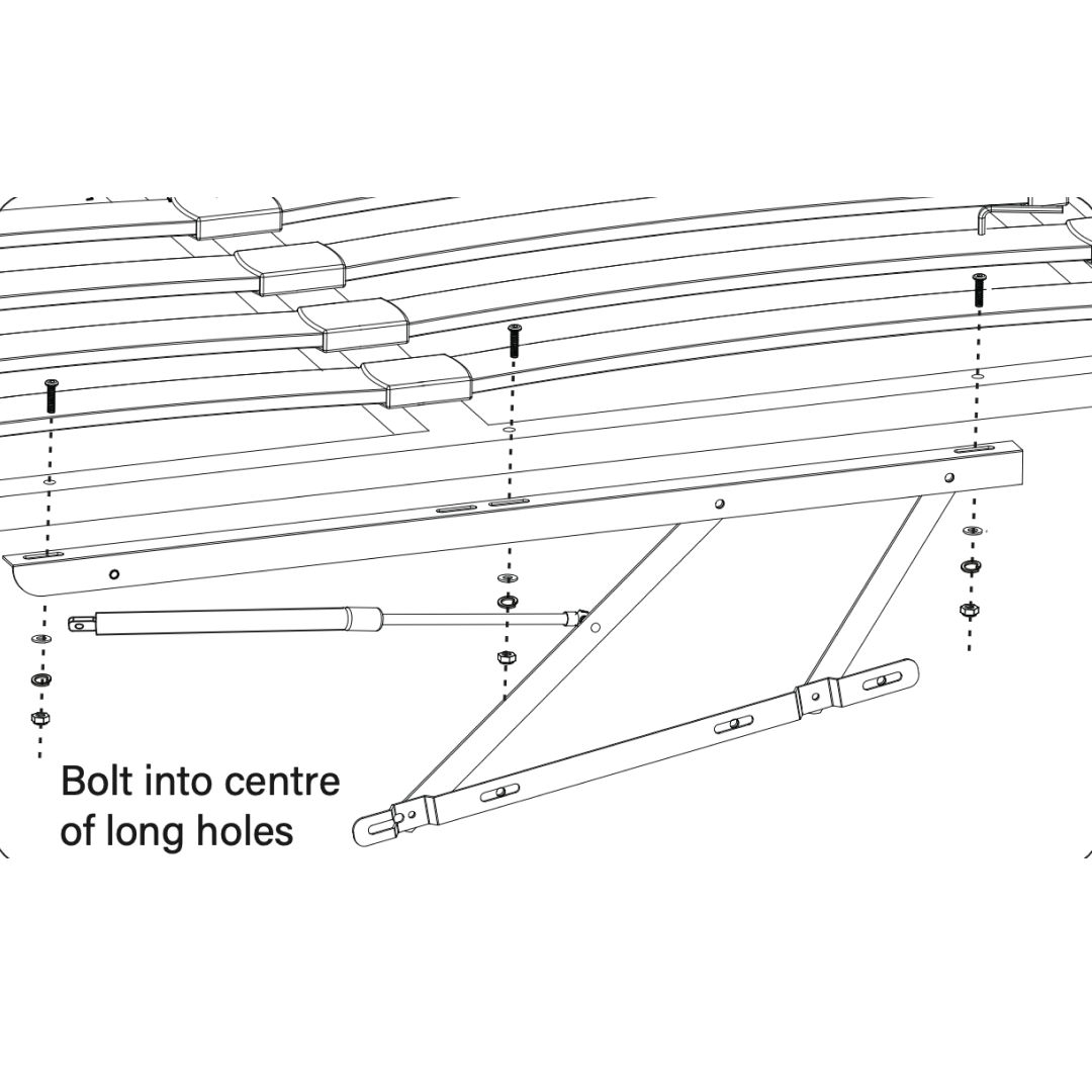
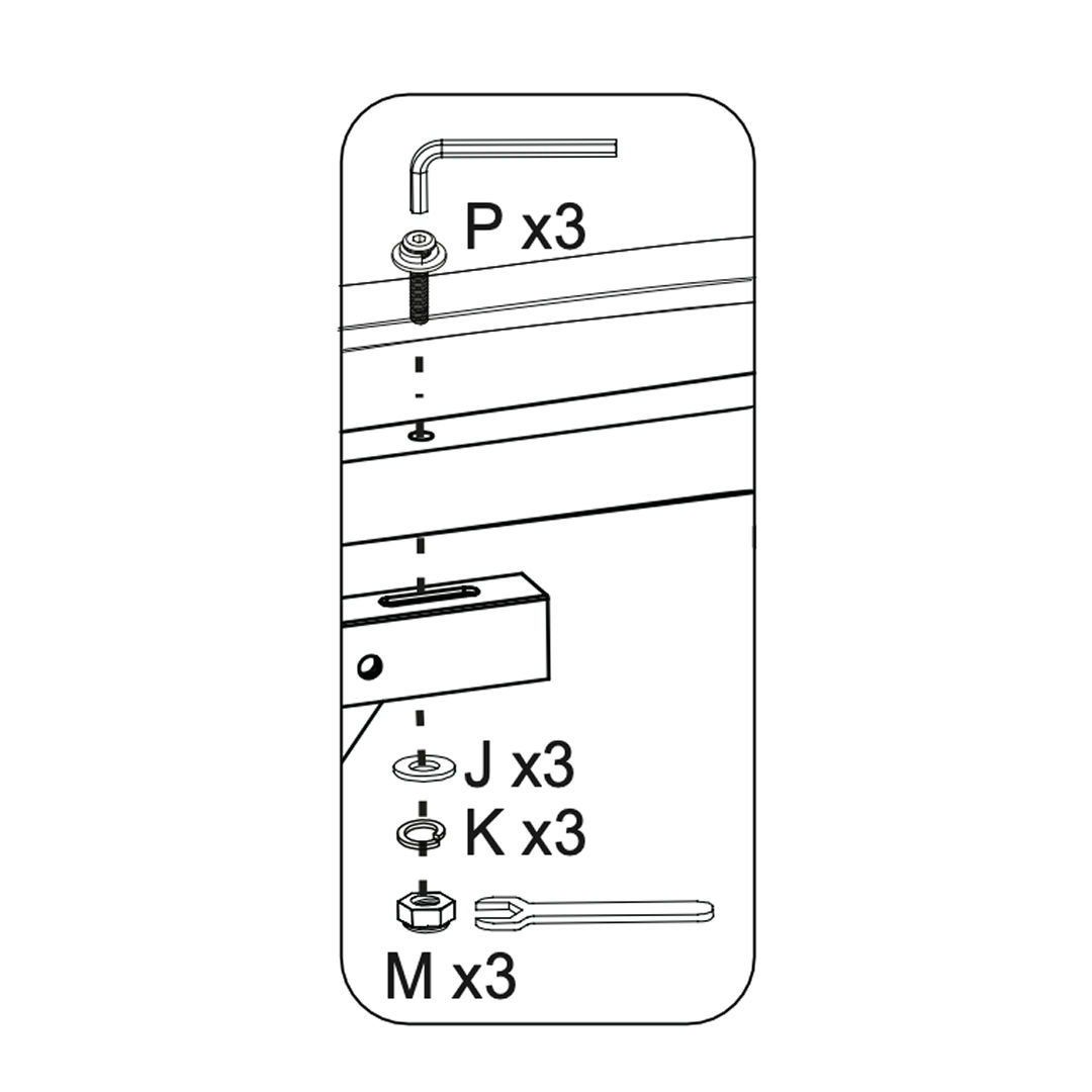
18. Attach the Slatted Base
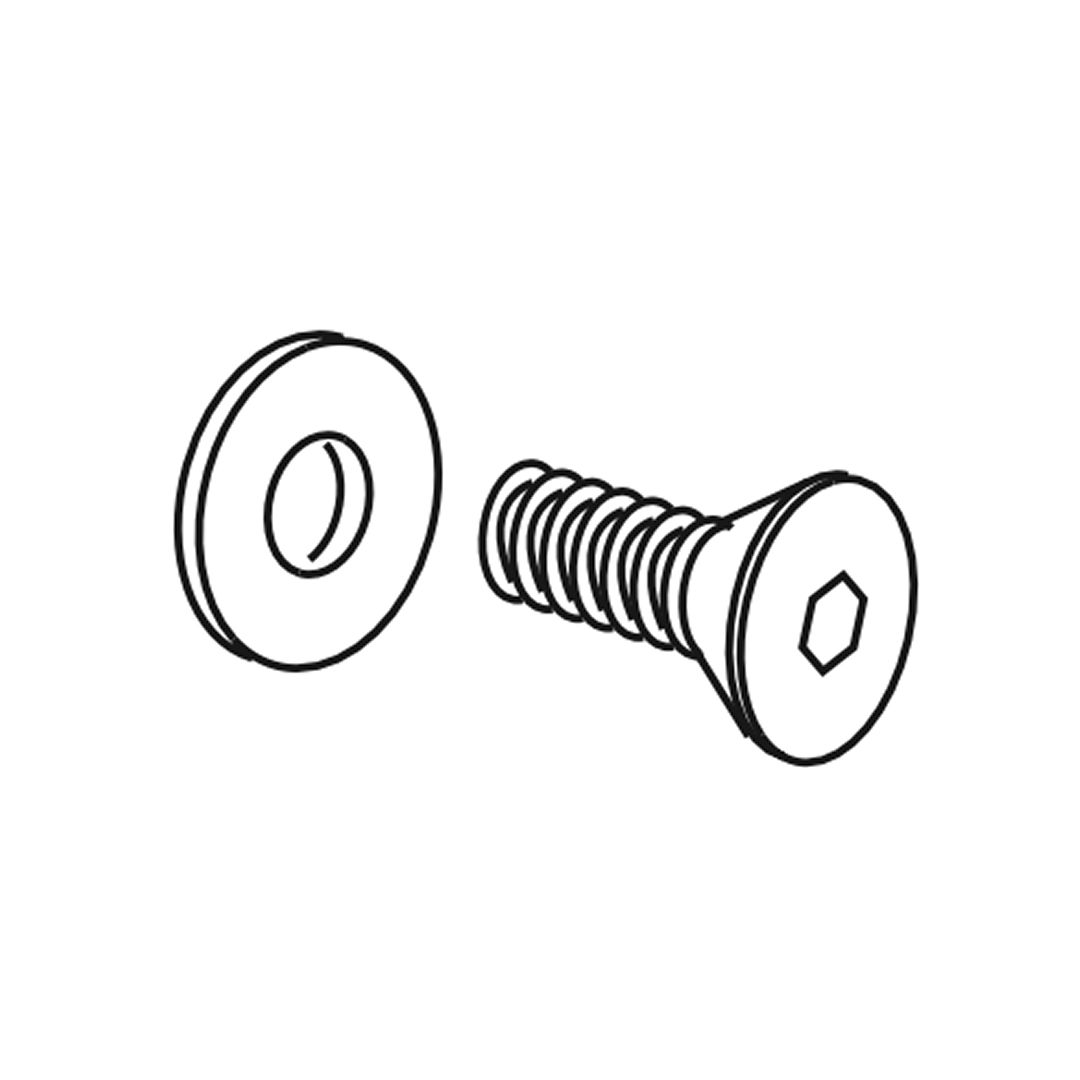
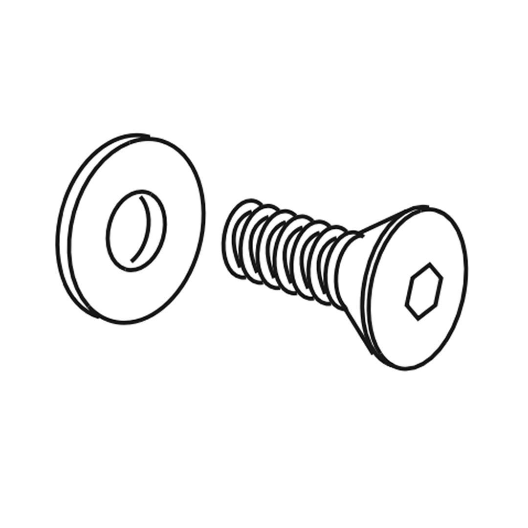
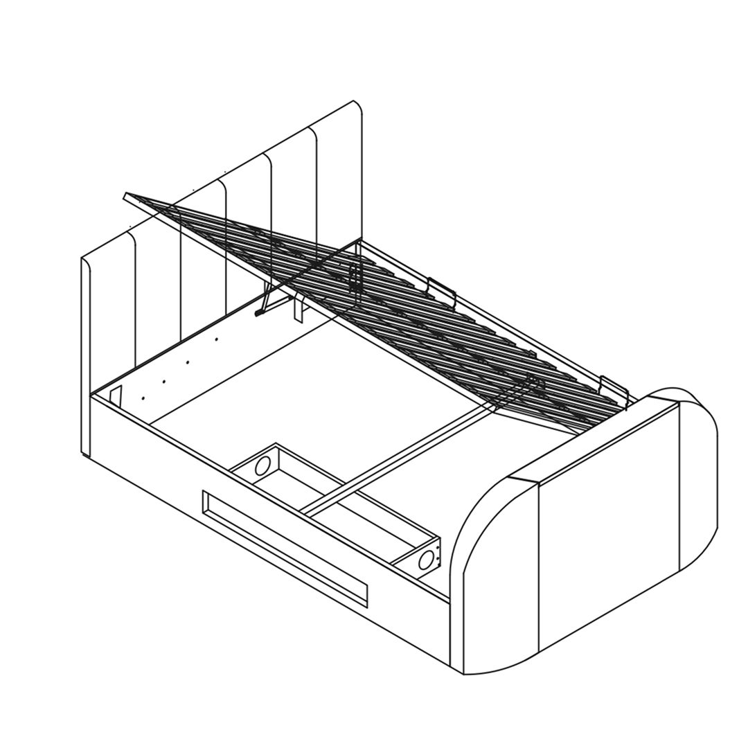
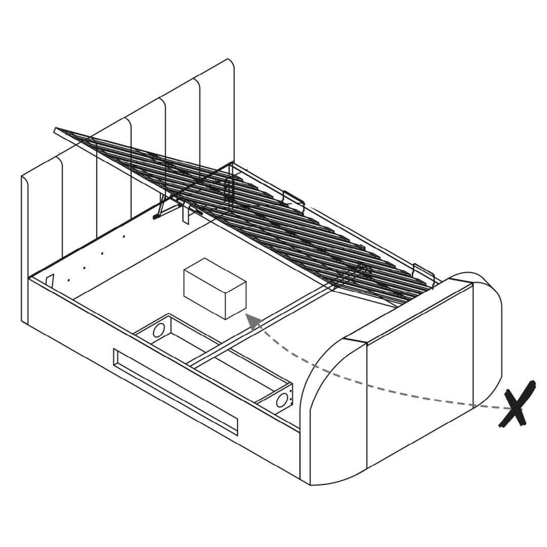
1. Position the slatted base over the bed frame, ensuring it is centered and aligned properly. 2. Use bolts (P) to secure the slats to the frame. Insert the bolts through the designated holes in the slats and into the frame. 3. Place washers (J and K) over the bolts, followed by nuts (M). Tighten the nuts using the provided wrench to ensure the slats are firmly secured. 4. Attach the gas lift mechanism to the frame by bolting it into the center of the long holes on the support arms. Ensure the mechanism is securely fastened. 5. Gently lift the slatted base to ensure the gas lift mechanism operates smoothly and the base raises and lowers without obstruction.
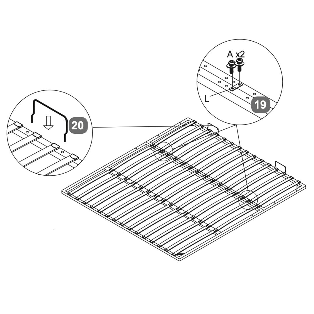
19. Attach the lift mechanism
Slide gas-lift cylinder stem (x) onto the axle (y) then fit the flange lock-nut (M). Tighten nut with spanner (N) do not over-tighten.
A small gap must be left so stem can move freely
20. Safety Warnings
Please do not allow children or pets inside the storage area.
Please be careful when lifting.
Only lift with mattress on top.
To be operated by adults only.
Only use the handle to lift & lower the bed frame to avoid trapping fingers!
To avoid accidents
To access the storage area the Ottoman frame must be fully opened and then fully closed afterwards
Be very careful what you store under the bed - the top of an item, like a suitcase or a box, must not touch the slats or they may be damaged.