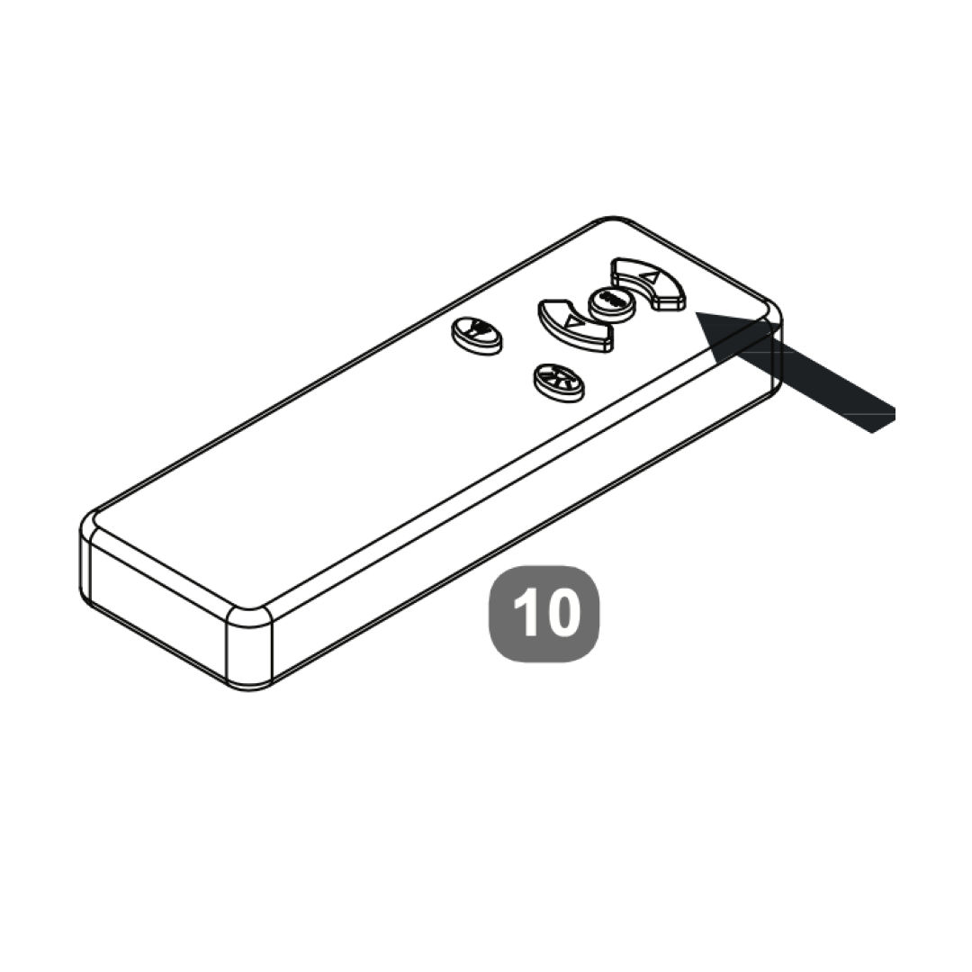
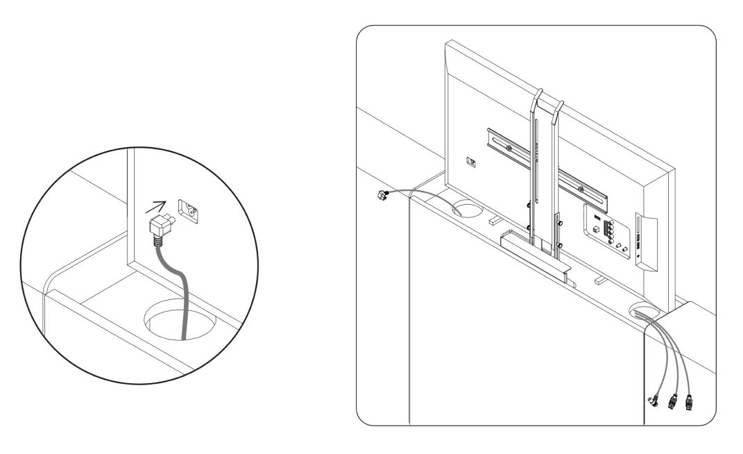
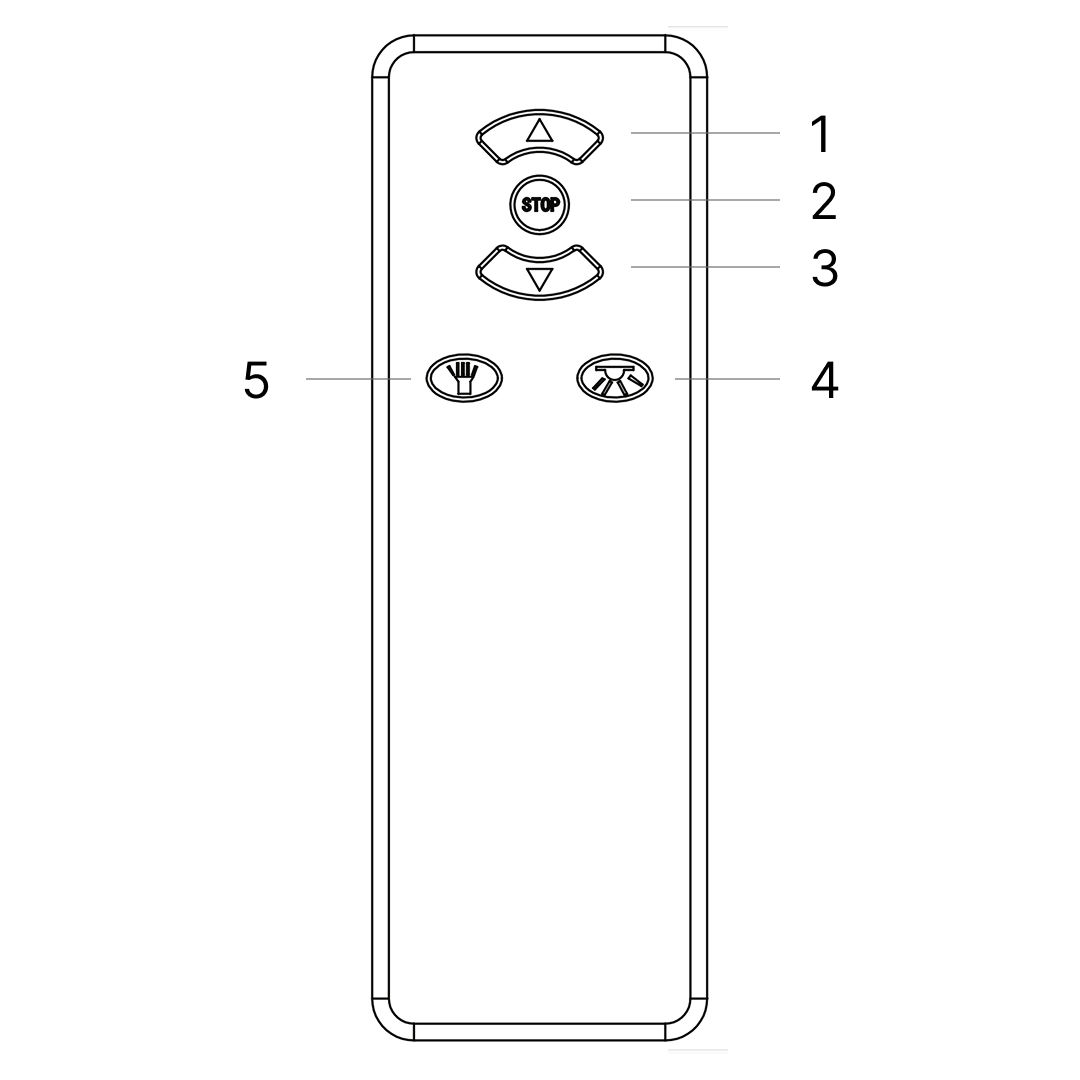
1. Press once and TV will rise to it's upper working position. Power to the TV will be connected automatically
2. Press once and TV Lift will stop.
3. Press once and TV will go down - as soon as the lower resting position is reached power to the TV is switched off to prevent it overheating.
4. Torch
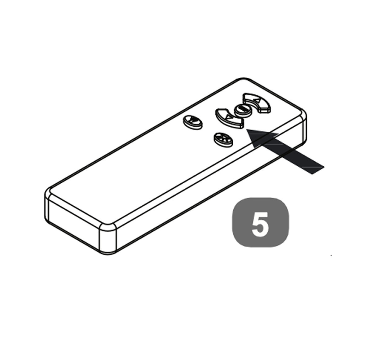
5. Code Matching
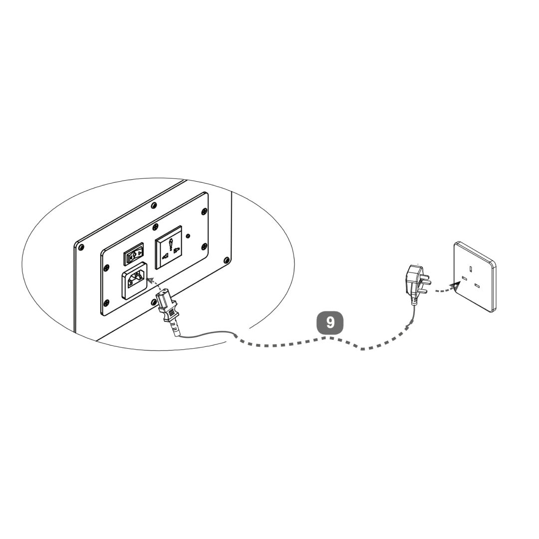
Code Matching (pairing): occasionally pairing is lost, perhaps due to atmospheric conditions,
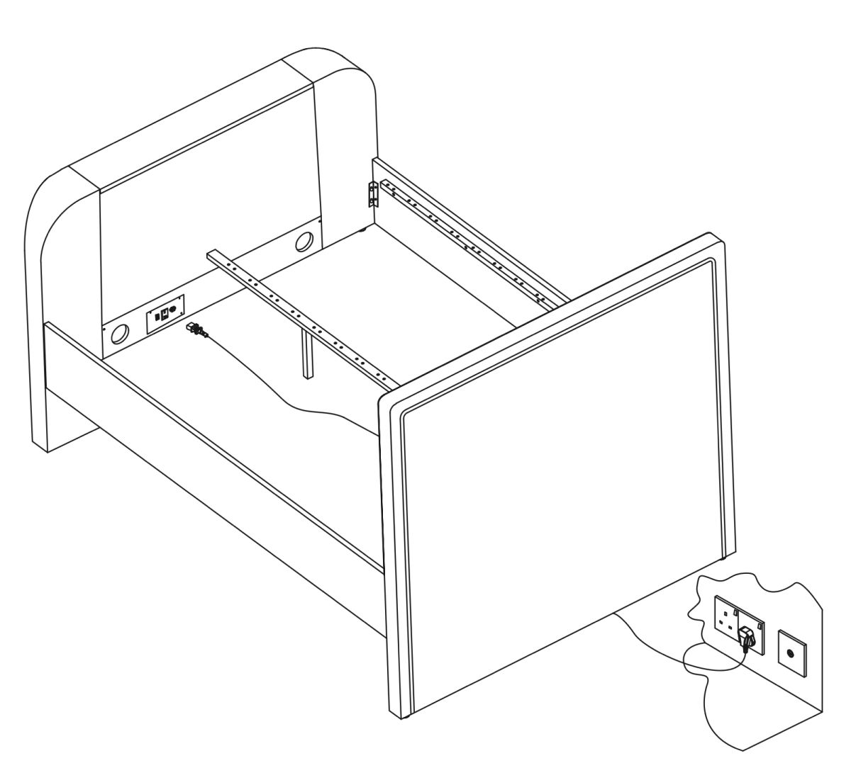
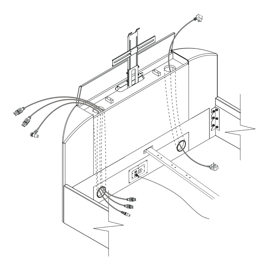
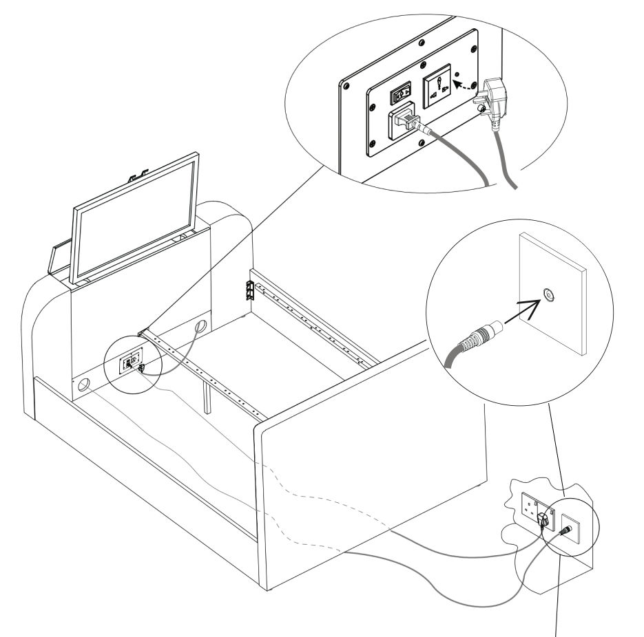
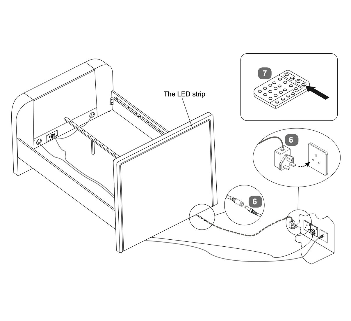
To re-pair - press and hold the code matching button whilst connecting the power by plugging the mains cable into the control box of the TV lift on the base of the footboard.
Continue to press the button for another 5 seconds then press the up or down button to successfully match the code.
Regularly check the batteries and if necessary re-place them - x3 pcs AAA size.