Assembly instructions for Lucca Wooden Ottoman Bed Frame by Time4Sleep
Product Information
Lucca Wooden Ottoman Bed Frame
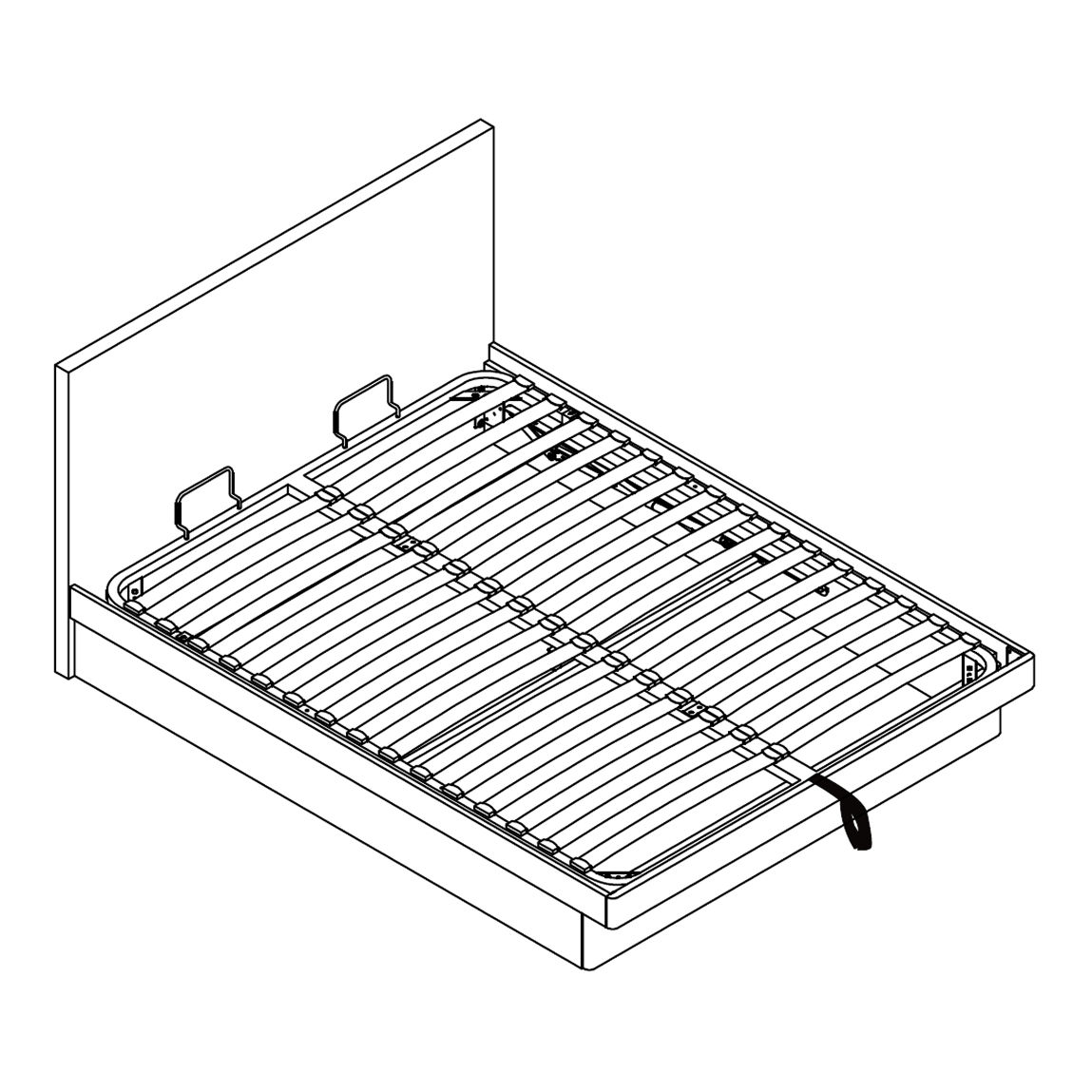
The Lucca Wooden Ottoman Bed Frame combines timeless design with modern functionality. Its strong wooden structure offers long-lasting support, while the easy-lift ottoman mechanism reveals generous under-bed storage, ideal for keeping your bedroom tidy. A slatted headboard and clean lines give it a versatile look that complements both classic and contemporary interiors.
SKU
LucOtt46Wooden,LucOtt50Wooden
Tools
A - Bolt (M8x45mm)
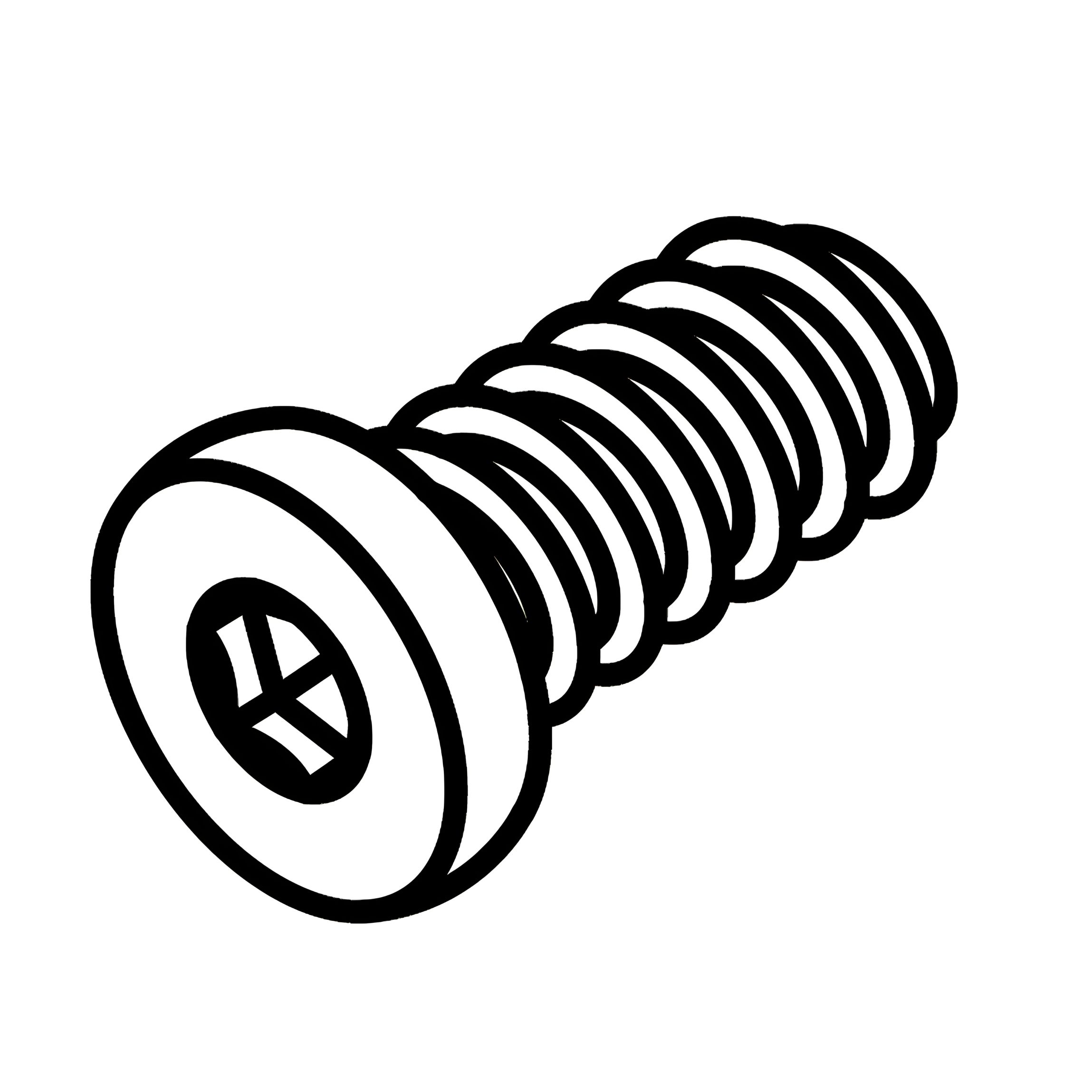
B - Bolt (M8x30mm)
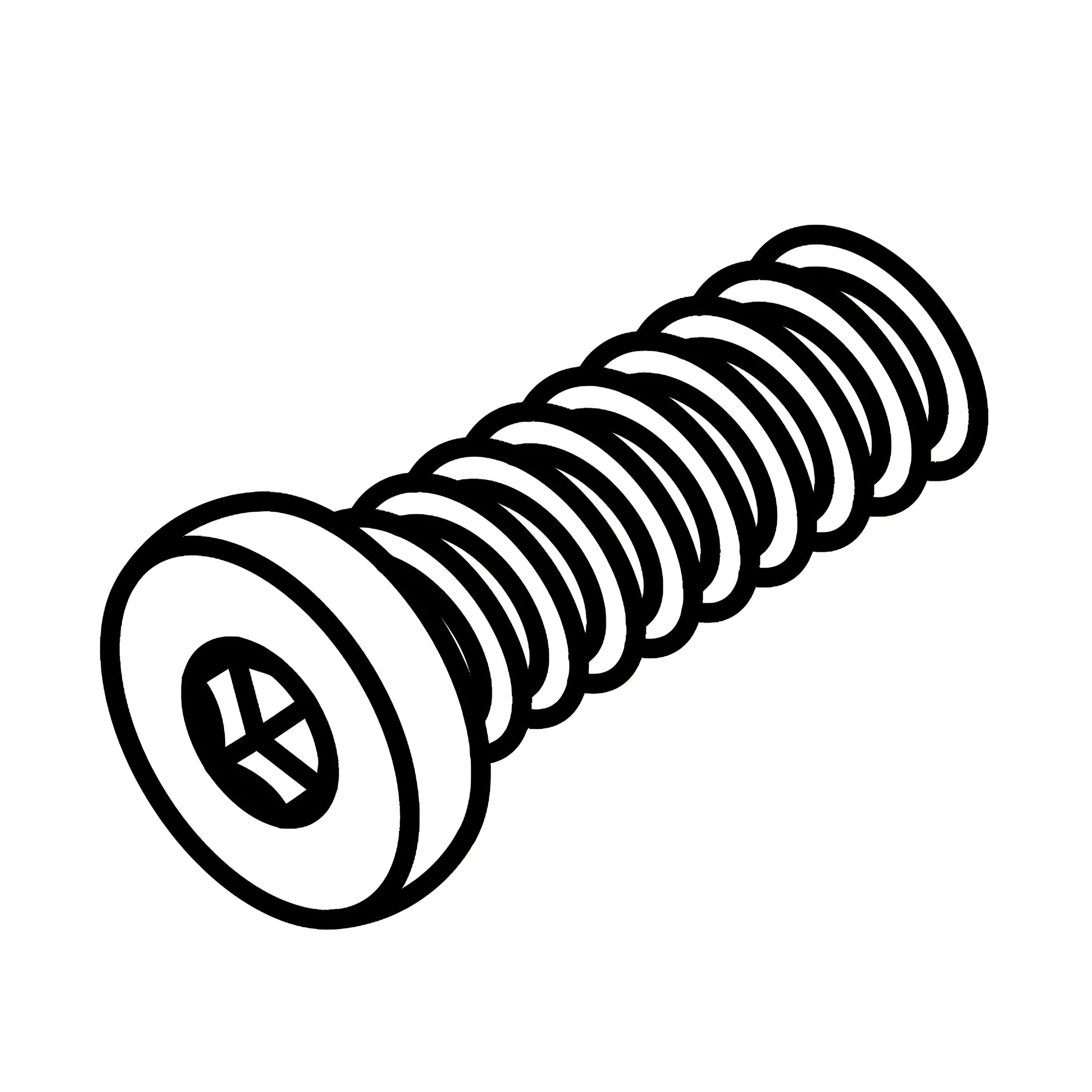
C - Bolt (M8x18mm)
D - Nut For M8 Bolt
E - Flanged Lock-Nut M8
F - Metal Connection Plates For Slat Frame
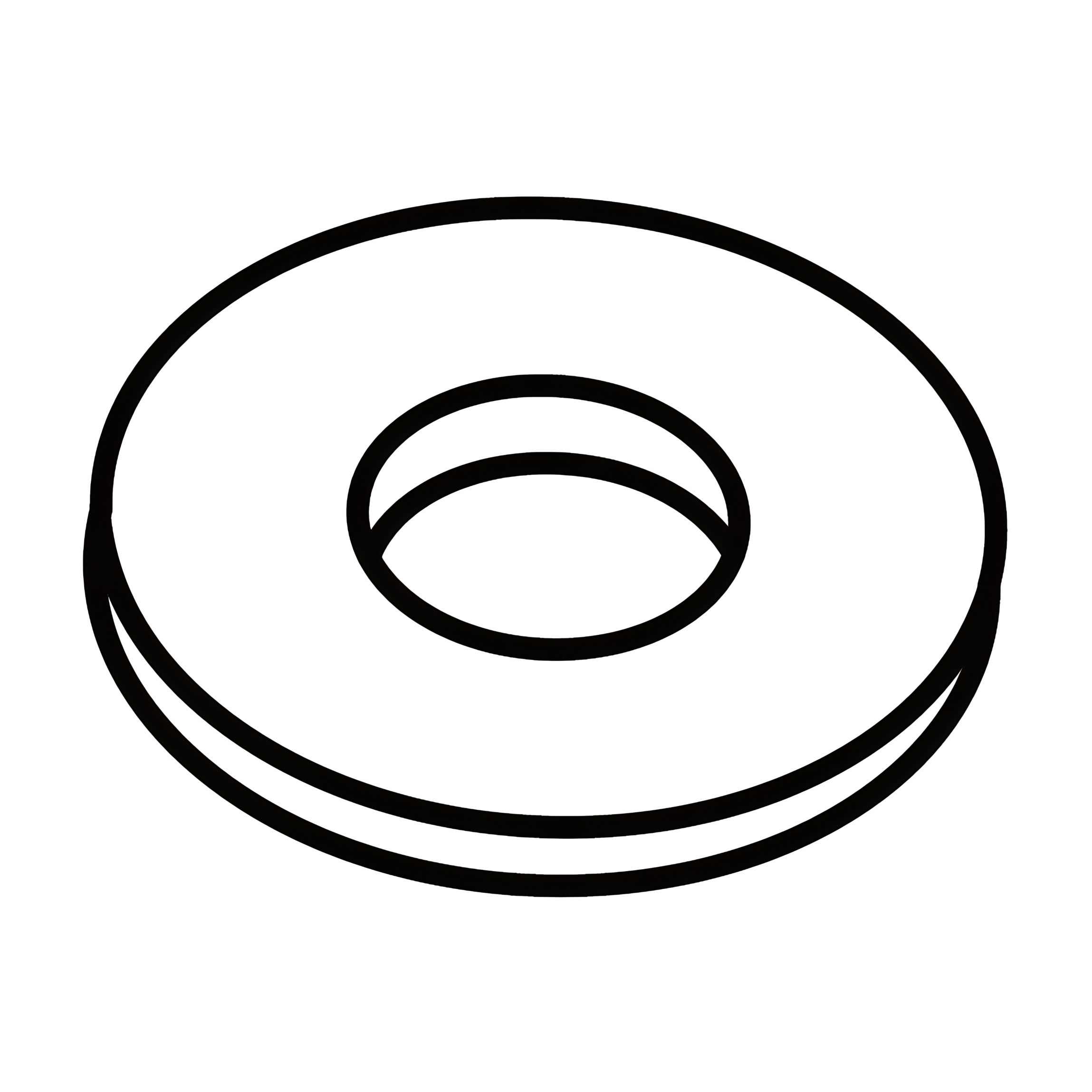
G - Flat Washer For M8 Bolts
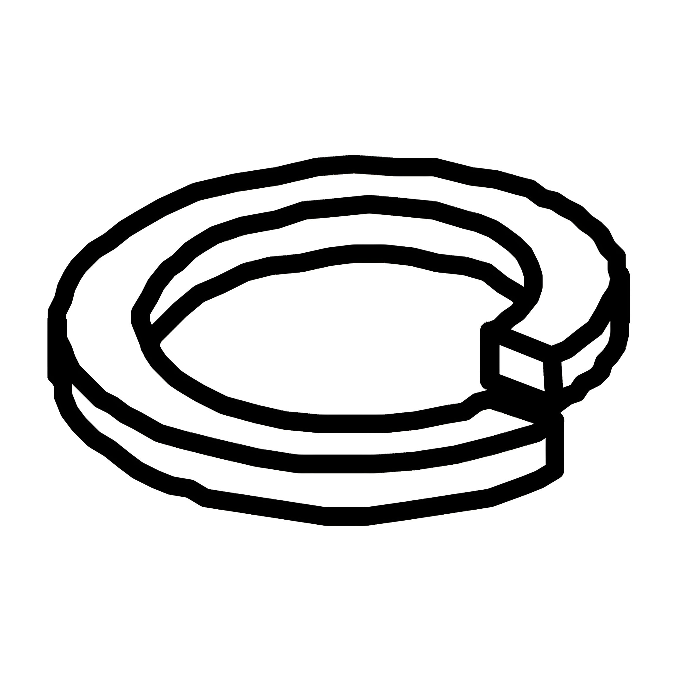
H - Spring Washer For M8 Bolts
I - Support Block For Side Rail Cross Bar
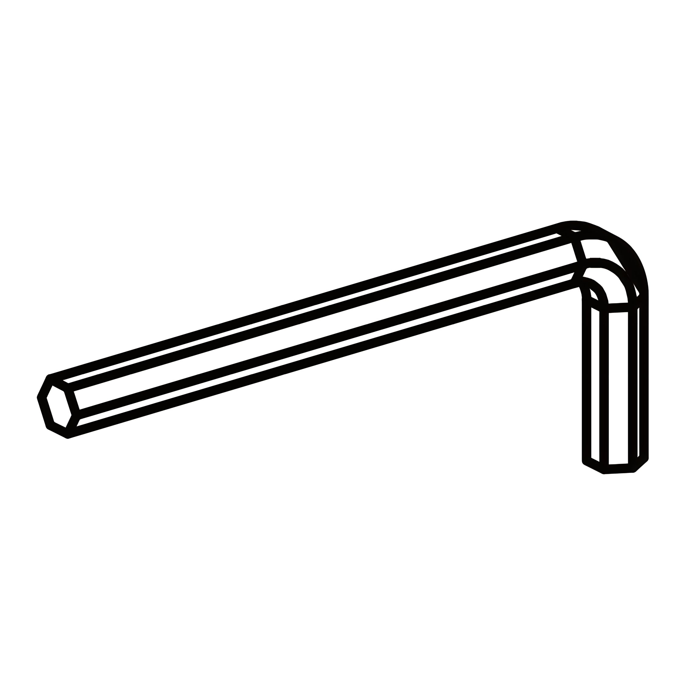
J - Allen Key For M8 Bolts
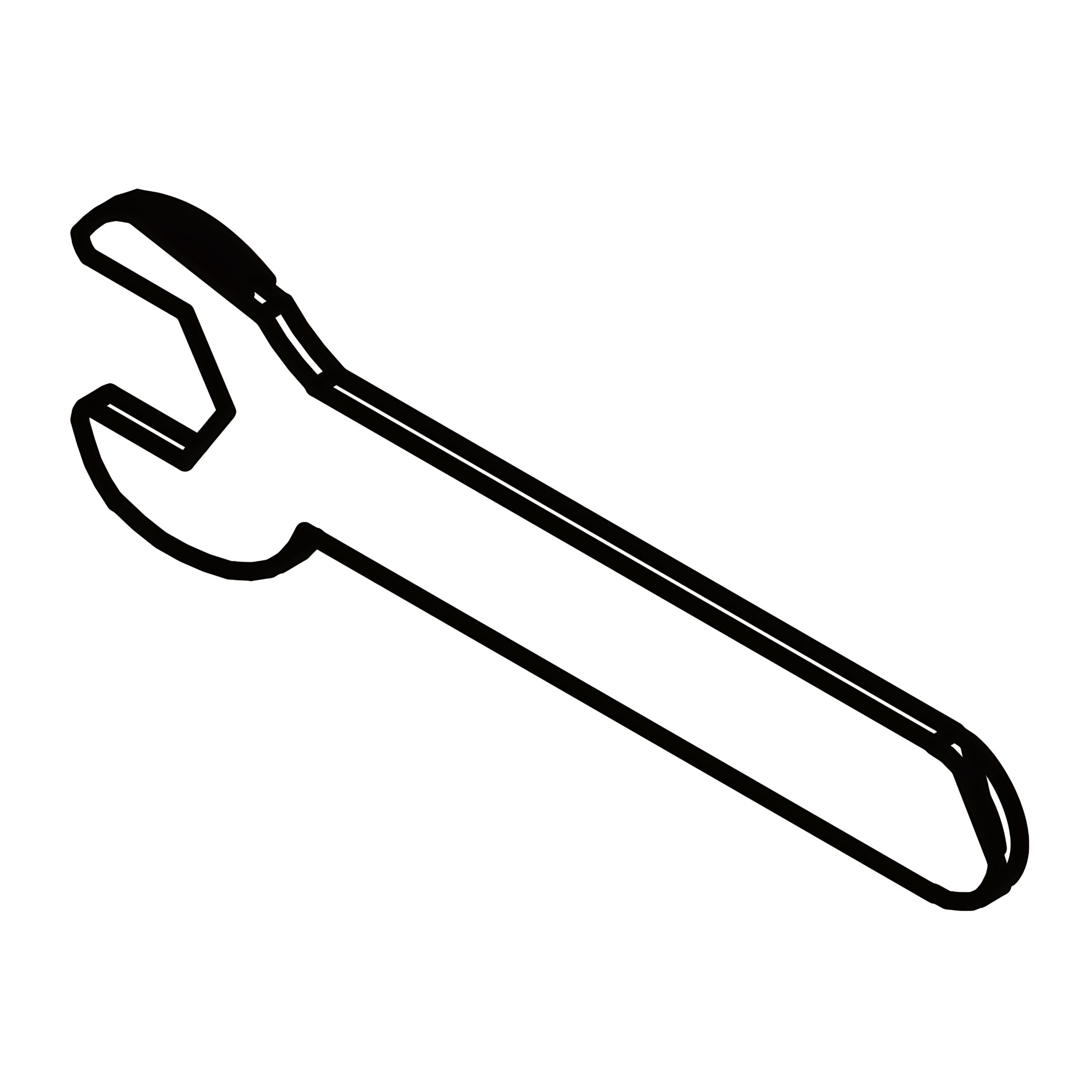
K - Spanner For M8 Nuts
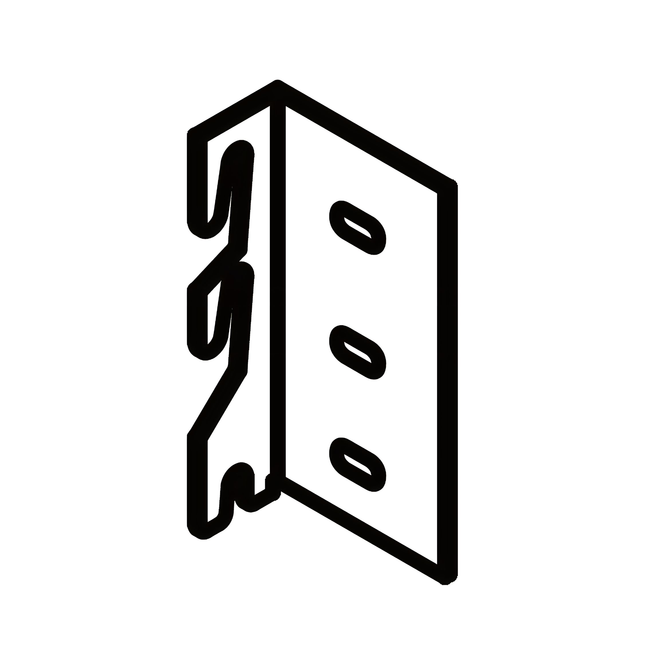
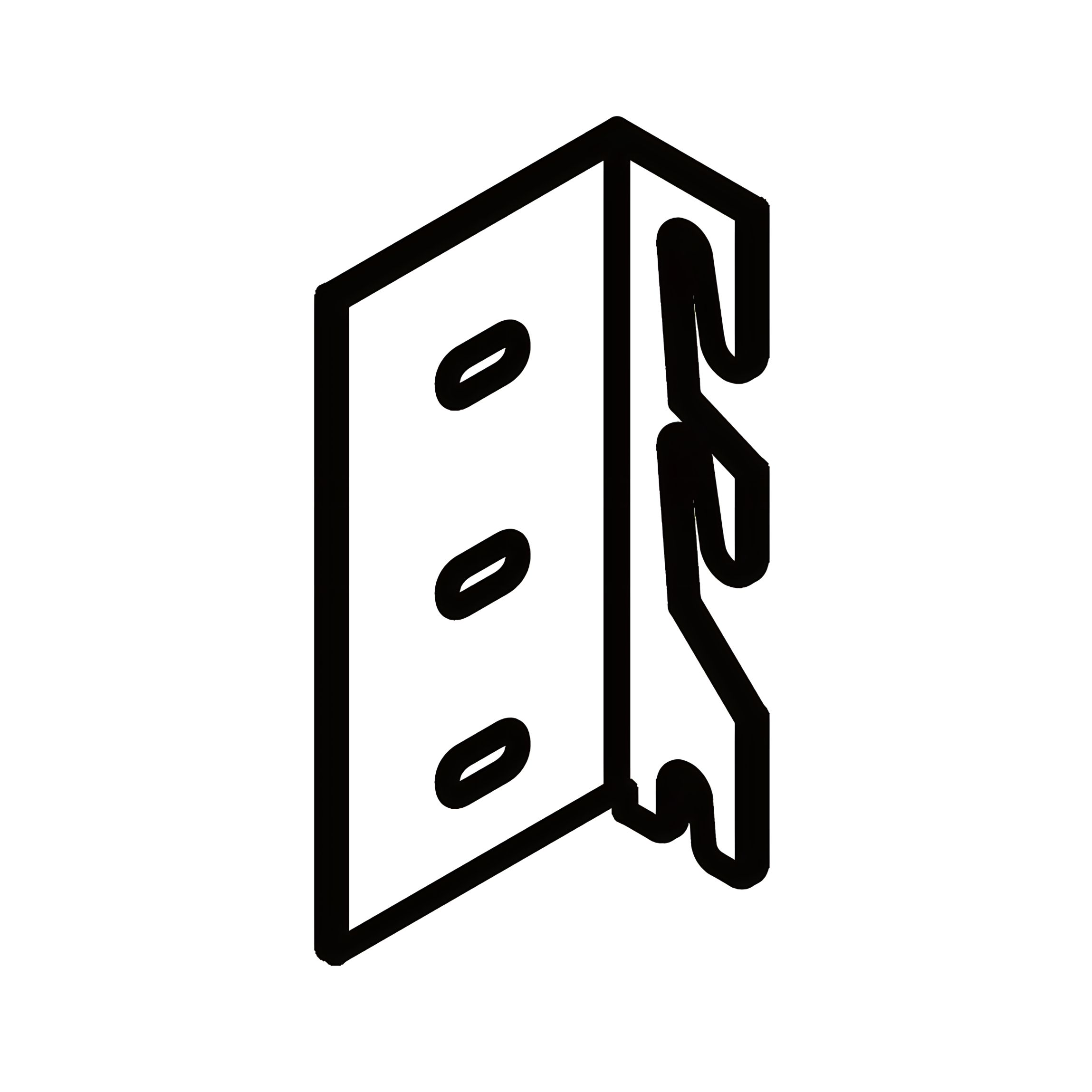
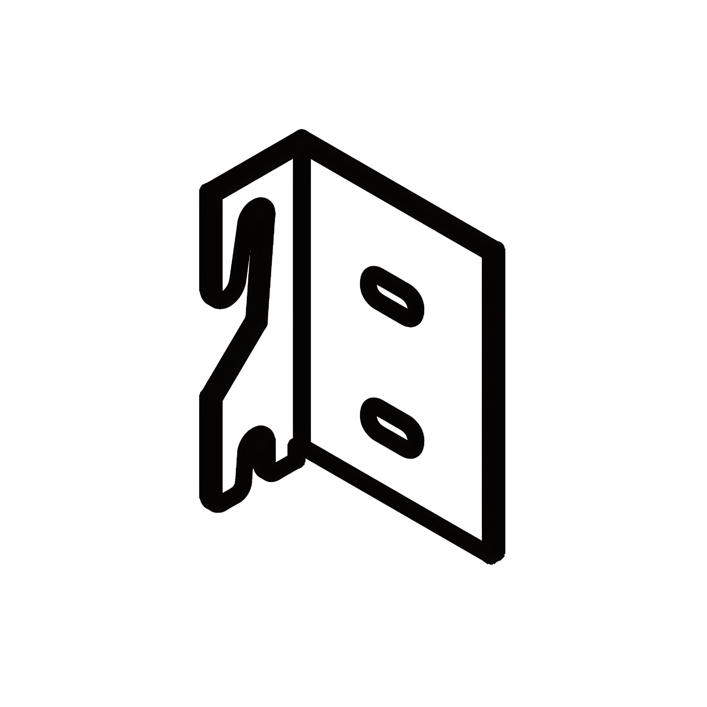
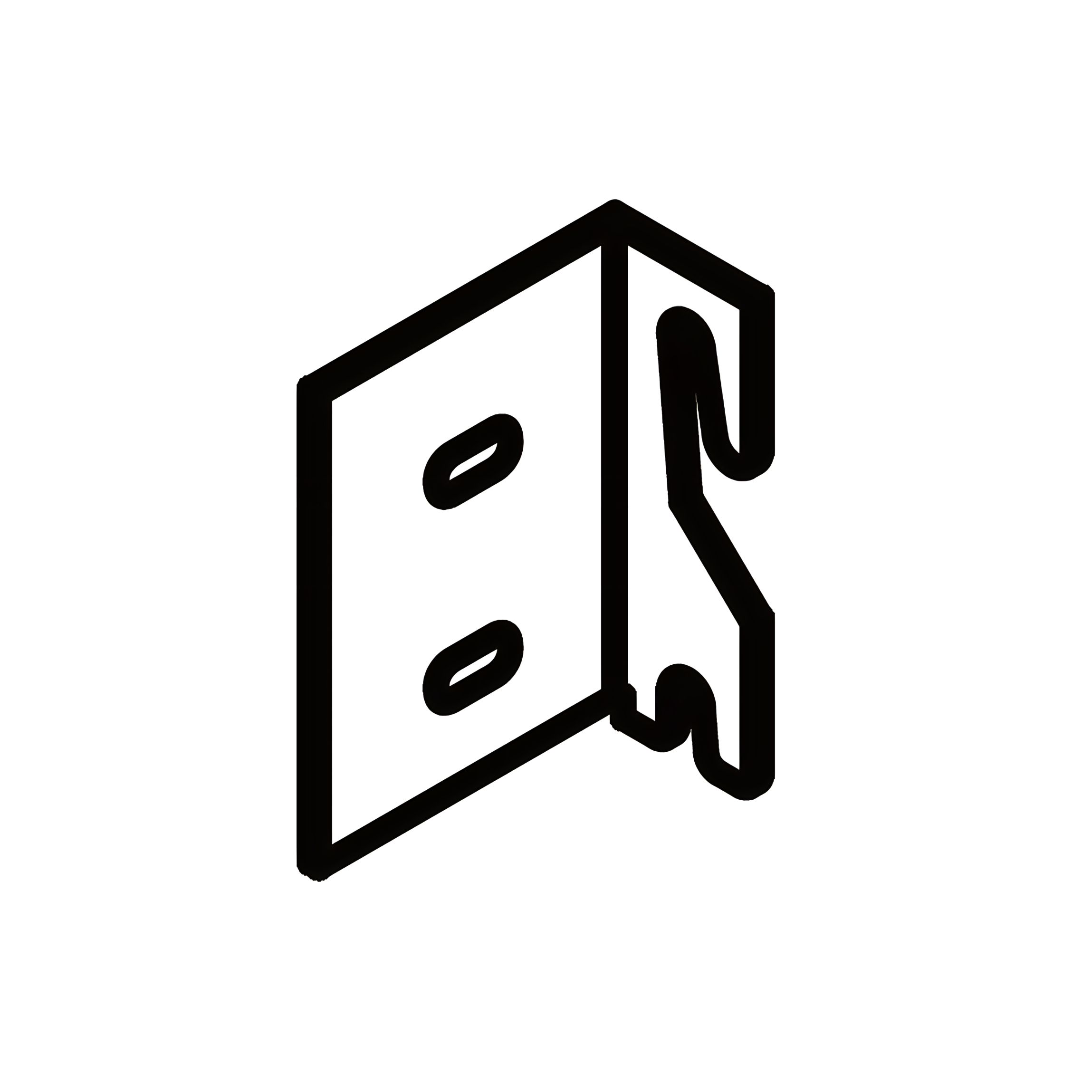
L - Corner Hook - Triple - Left
M - Corner Hook - Triple - Right
N - Corner Hook - Double - Left
O - Corner Hook - Double - Right
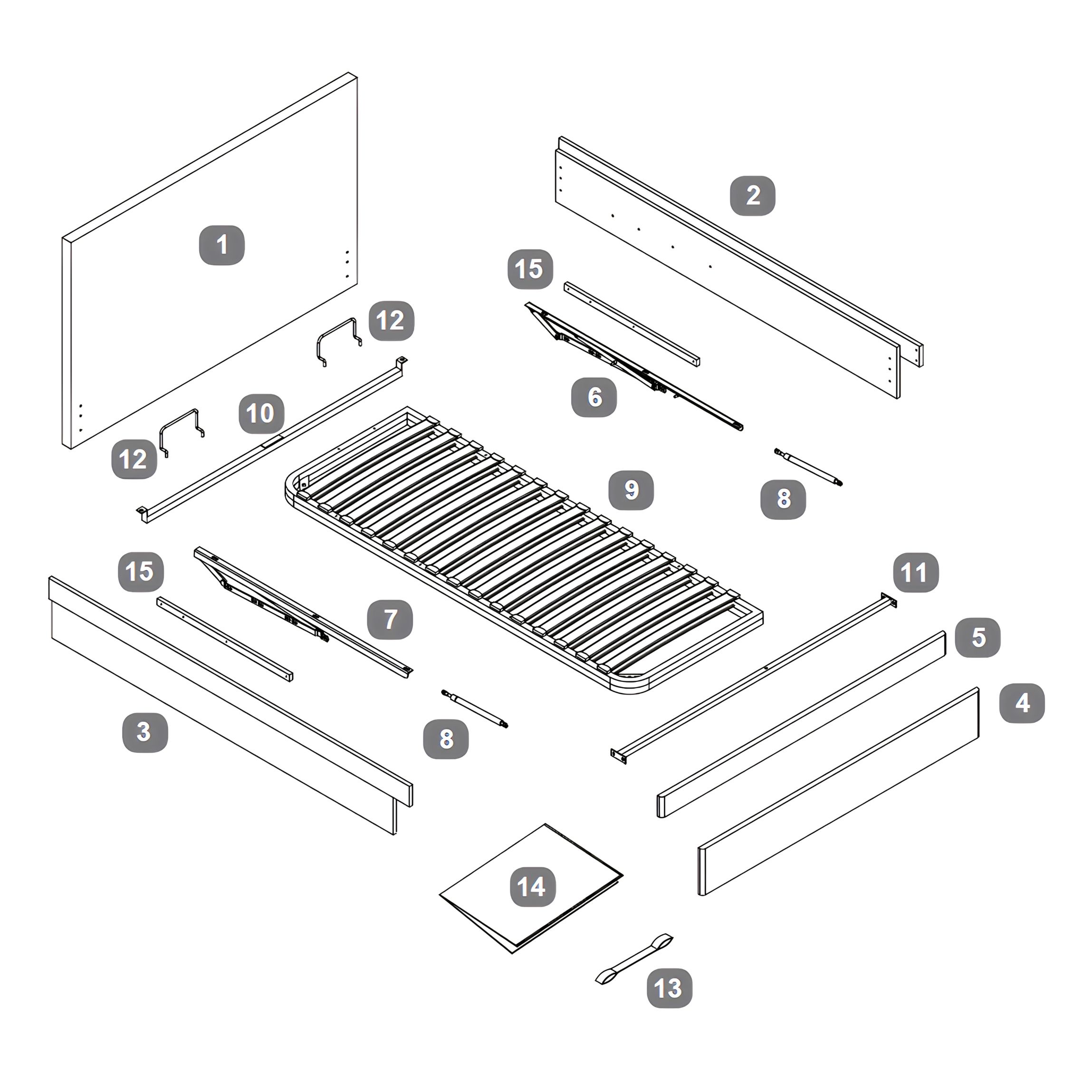
Parts
1Headboard
2Side Rail - RH
3Side Rail - LH
4Footboard - Lower
5Footboard - Upper
6Gas-lift Mechanism - Right
7Gas-lift Mechanism - Left
8Gas-lift Piston
9Metal Slat Frame
10Slat Frame Cross Bar
11Side Rail Cross Bar
12Mattress Stopper
13Fabric Hand Strap
14Fabric Base Cover
15Spacer Rail For Gas Lift Mechanism
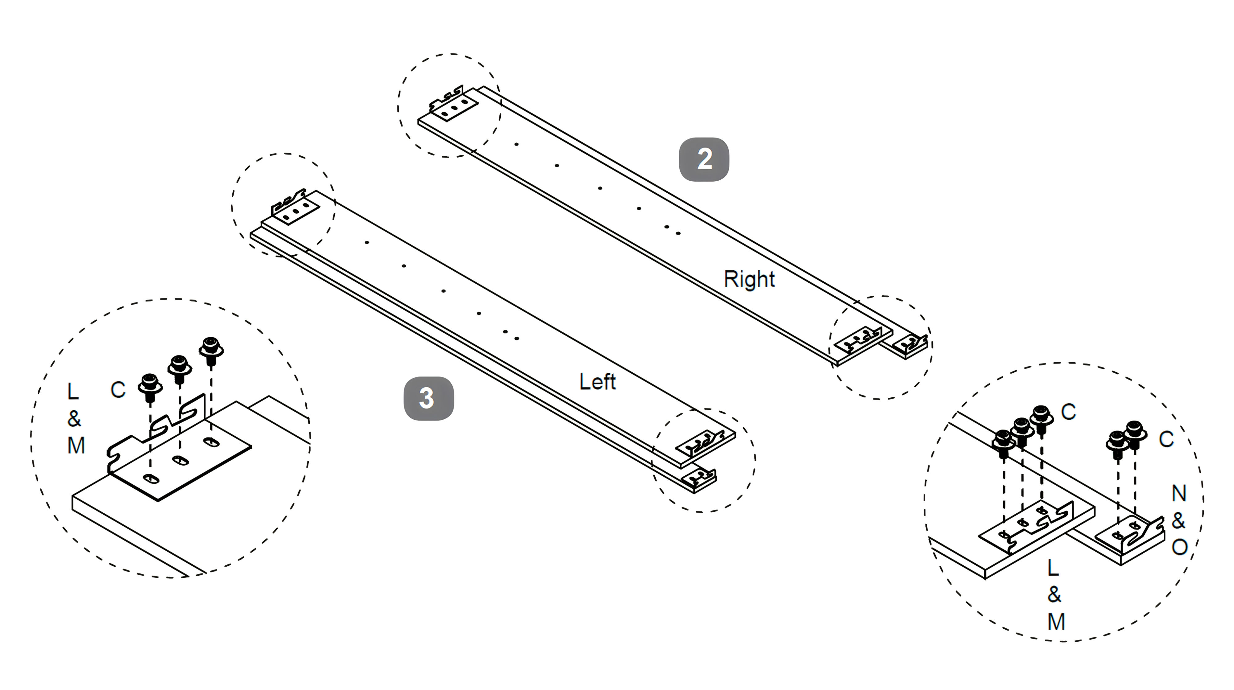
1. Corner Hook Attachment Process
1. Position the Side Rail – RH (2) and Side Rail – LH (3) with the pre-drilled holes facing upward. 2. Attach the Corner Hooks – Triple (L & M) to the ends of the side rails using Bolt (M8x18mm) (C), a Flat Washer (G), and a Spring Washer (H) for each hole. Make sure the hooks are flush and firmly secured. 3. Next, fix the Corner Hooks – Double (N & O) to the interior faces of each side rail, also using Bolt (M8x18mm) (C) with Flat Washer (G) and Spring Washer (H). 4. Once all hooks are aligned and in place, tighten all bolts securely.
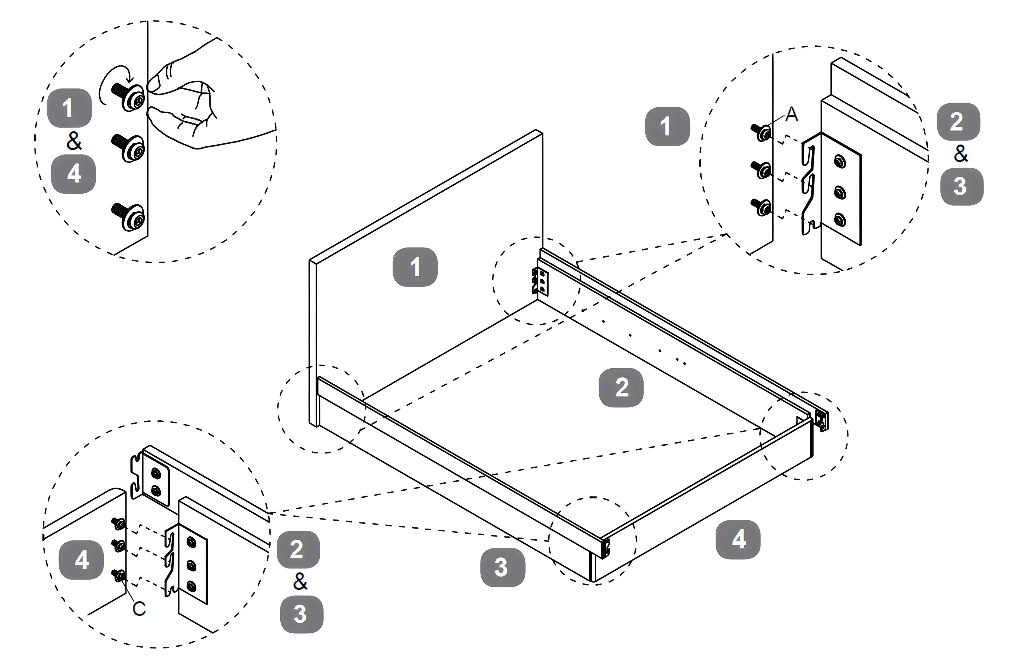
2. Attach Headboard and Footboard
1. Stand the Headboard (1) and Footboard – Lower (4) upright. 2. Insert a Bolt (M8x45mm) (A) along with a Flat Washer (G) and a Spring Washer (H) into each of the pre-drilled holes on the headboard, do not fully tighten. 3. Hook the brackets of the Side Rail – RH (2) and Side Rail – LH (3) onto the bolts. 4. Repeat the same process at the footboard using Bolts (M8x18mm) (C) with a Flat Washer (G) and a Spring Washer (H). 5. Once all corner hooks are properly engaged, fully tighten all bolts to secure the frame.
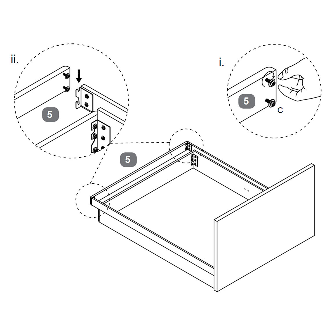
3. Upper Footboard Assembly
1. Position the Upper Footboard (5) between the Side Rail – RH (2) and Side Rail – LH (3). 2. Insert Bolts (M8x18mm) (C) along with a Flat Washer (G) and a Spring Washer (H) into the pre-drilled holes at the ends of the side rails, do not fully tighten. 3. Hook the Upper Footboard (5) onto the Corner Hooks – Double – Left (N) and Right (O). 4. Ensure the brackets are fully engaged, then tighten all bolts securely.
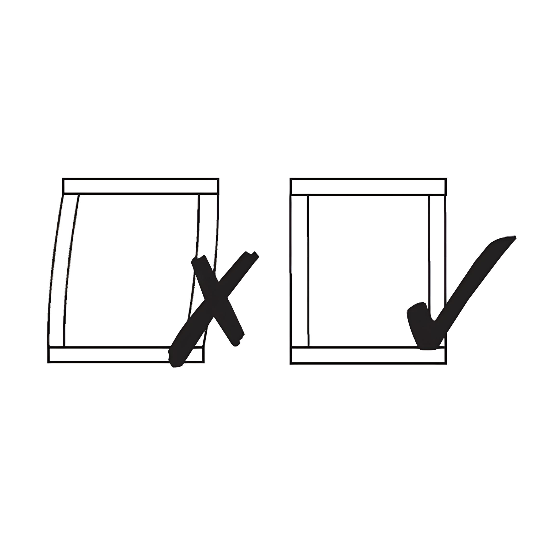
Important: Make sure the bed frame is squared, as shown in the diagram, before tightening all bolts completely. This ensures proper alignment and long-term stability.
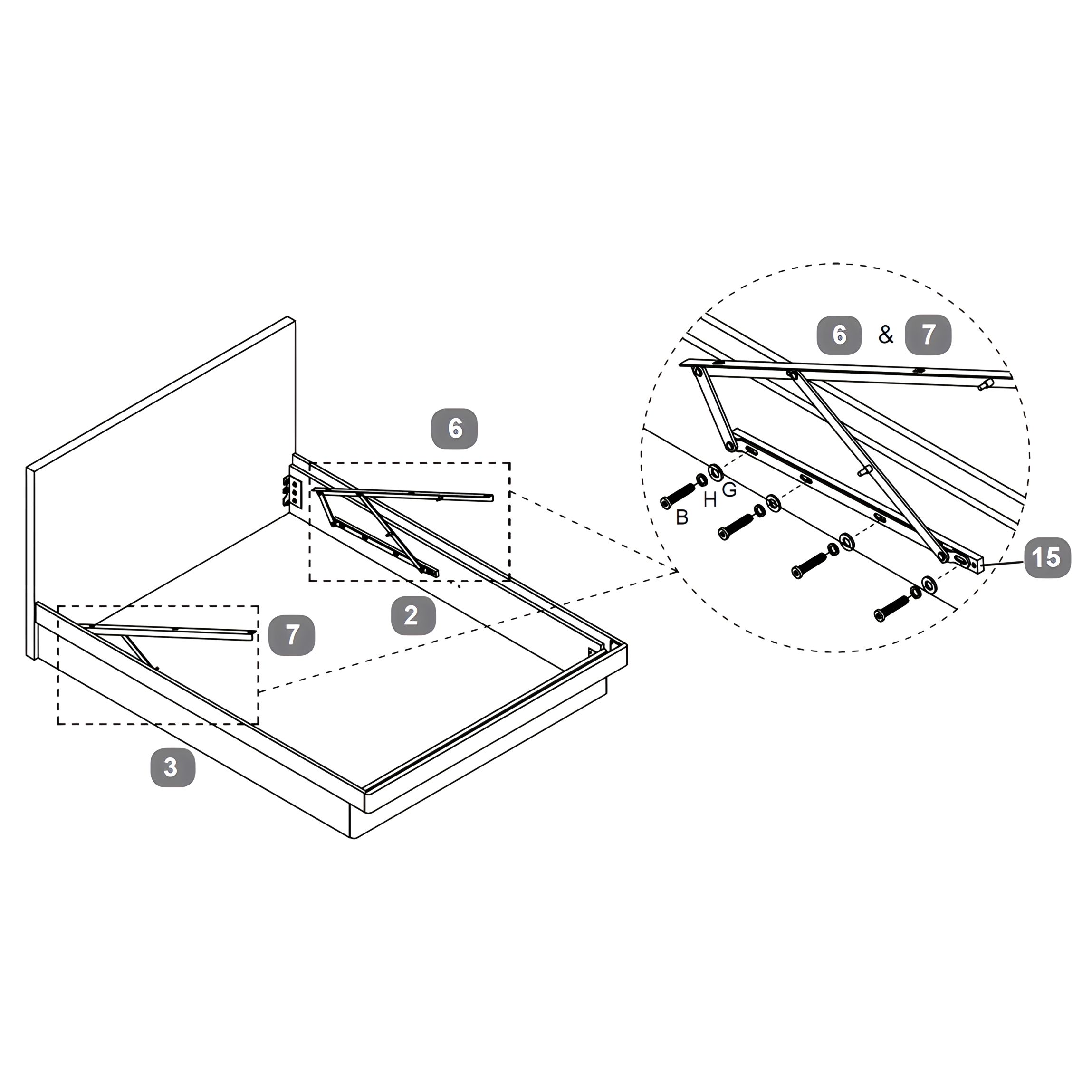
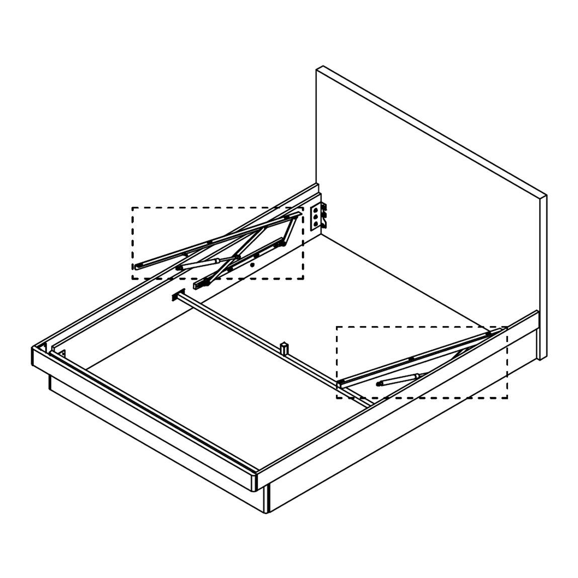
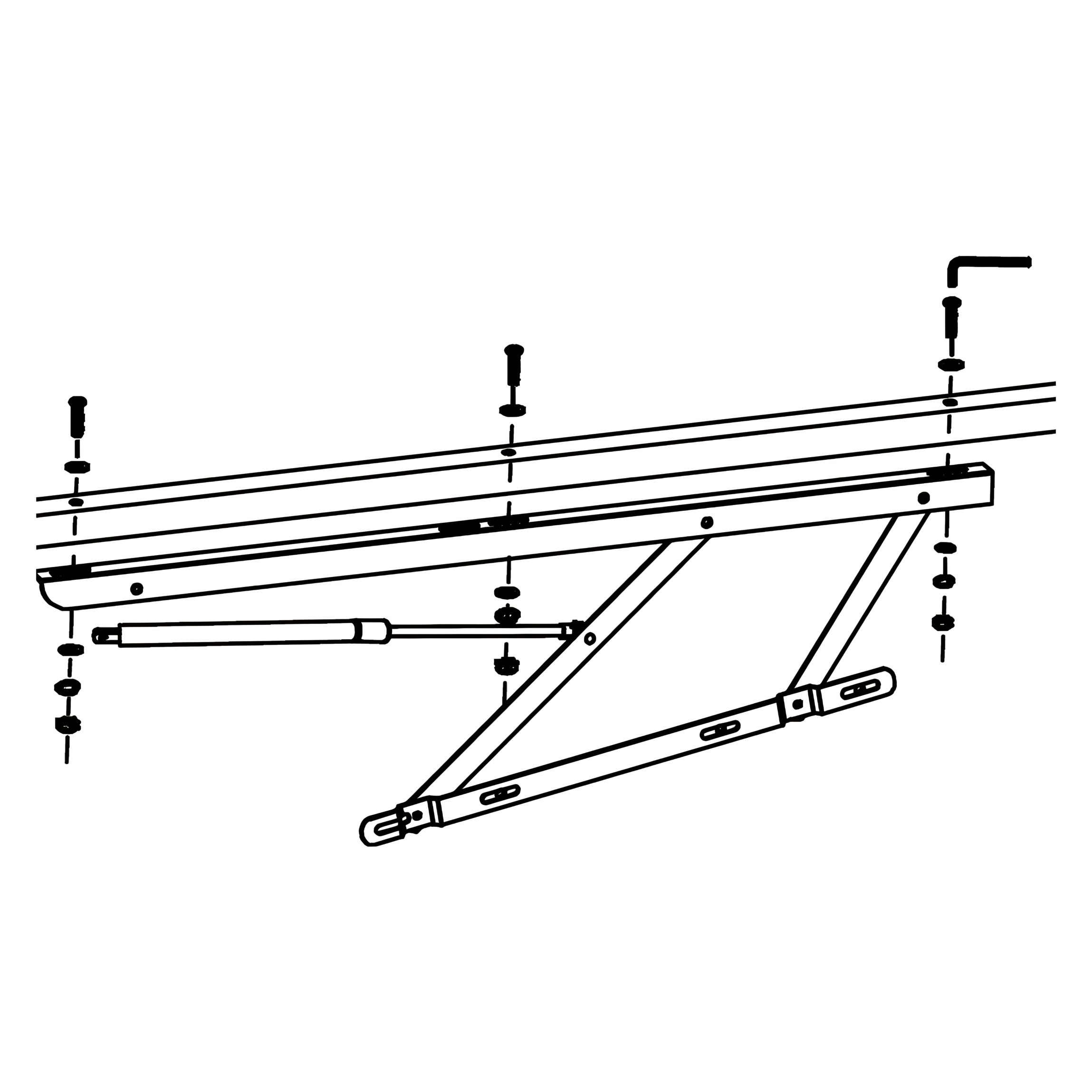
4. Attach the Gas-Lift Mechanisms to the Side Rails
1. Place the Spacer Rails (15) underneath the gas-lift mechanisms as shown. These must be installed first, as they sit underneath the gas-lift arms. 2. Position the Gas-lift Mechanism – Right (6) and Gas-lift Mechanism – Left (7) onto the Side Rail – RH (2) and Side Rail – LH (3) respectively, aligning them with the pre-drilled holes. 3. Secure each mechanism using Bolt (M8x30mm) (B), together with a Flat Washer (G) and a Spring Washer (H). 4. Tighten all bolts fully to ensure the mechanisms are securely fixed to the side rails.
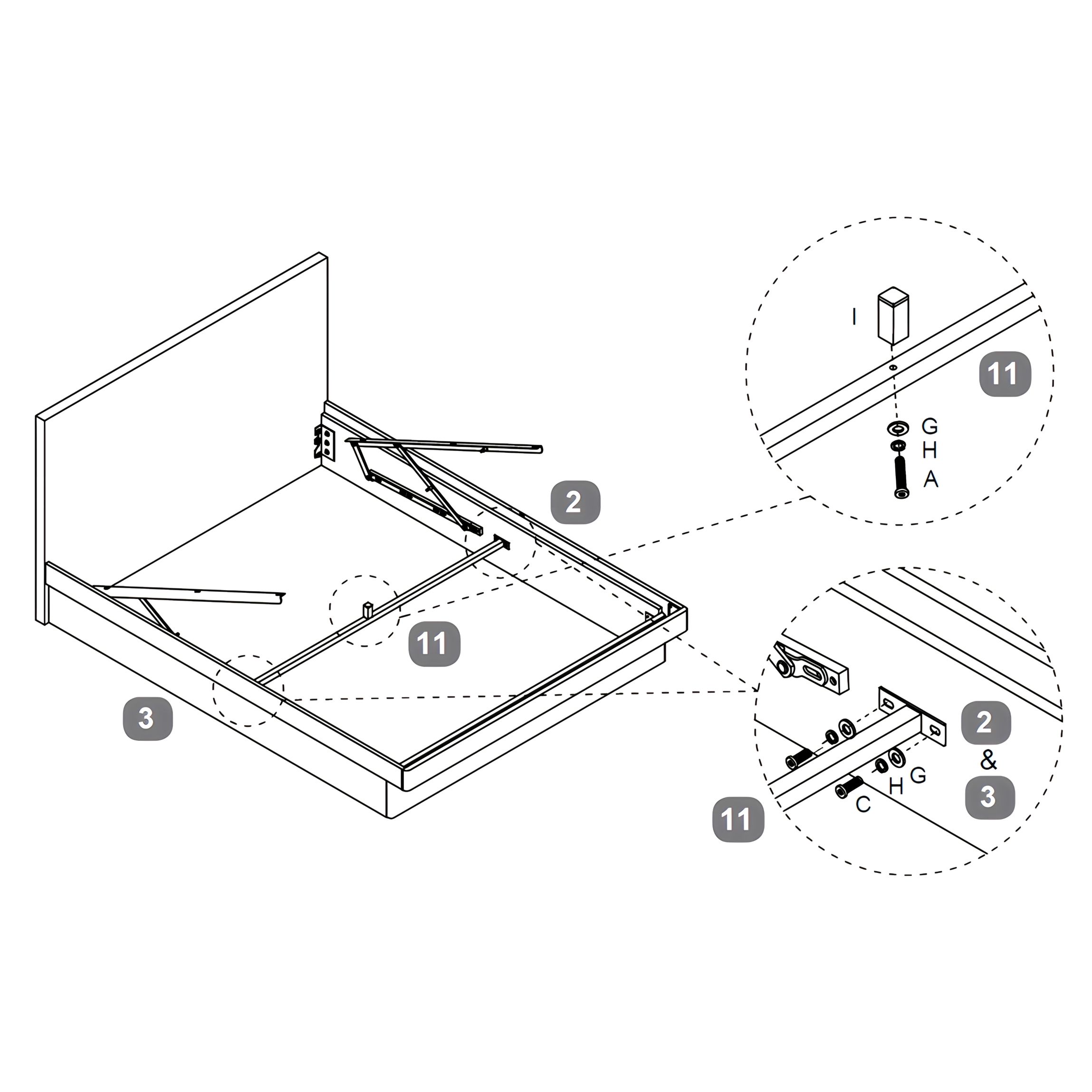
5. Install the Side Rail Cross Bar
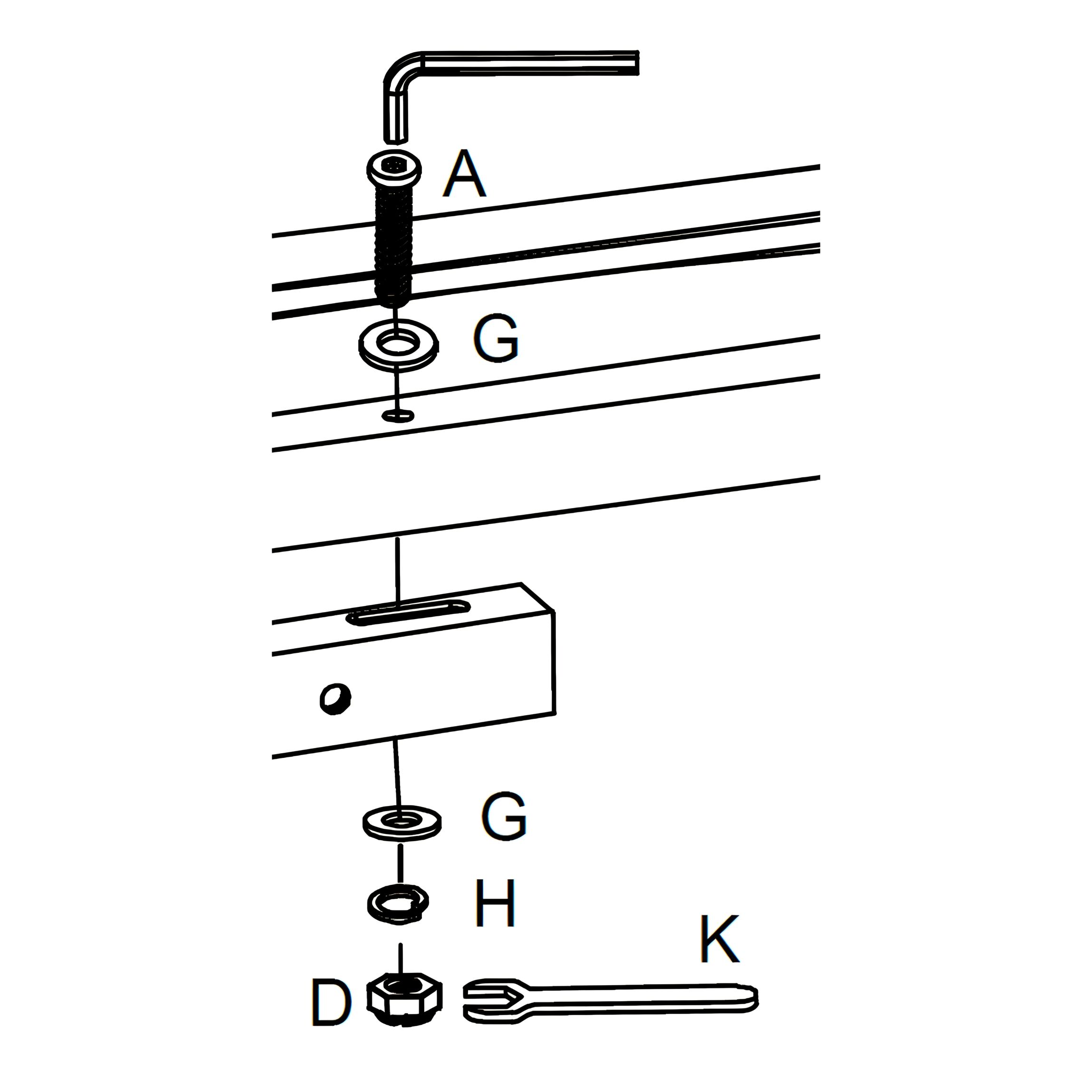
1. Position the Side Rail Cross Bar (11) between the Side Rail – RH (2) and Side Rail – LH (3), aligning the ends with the pre-drilled holes. 2. At each end, secure the cross bar using Bolt (M8x18mm) (C), Flat Washer (G), and Spring Washer (H). Tighten the bolts to lock the bar in place. 3. Next, insert a Bolt (M8x45mm) (A) through the hole in the center of the cross bar, along with a Flat Washer (G) and Spring Washer (H). 4. Fix the Support Block (I) onto the underside of the bolt and tighten securely.
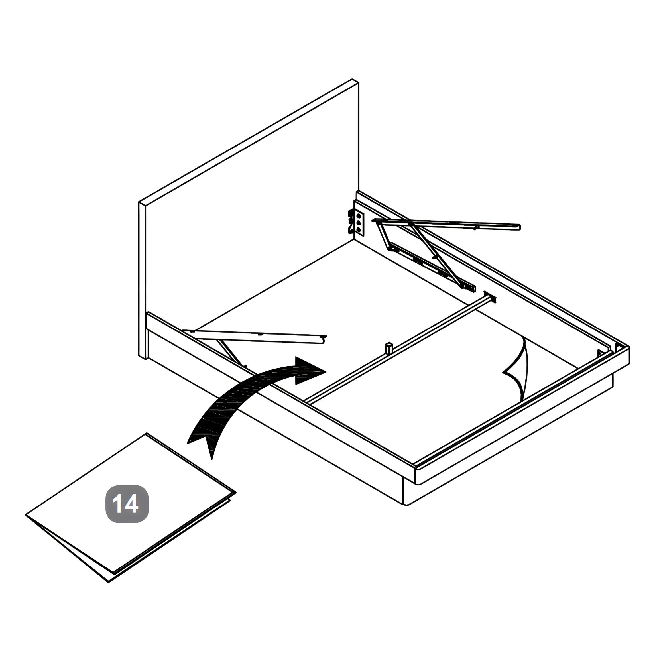
6. Place the Fabric Base Cover
Lay the Fabric Base Cover (14) flat inside the storage area, resting on the floor panel between the side rails.
Ensure it fits neatly within the frame and covers the entire internal base surface.
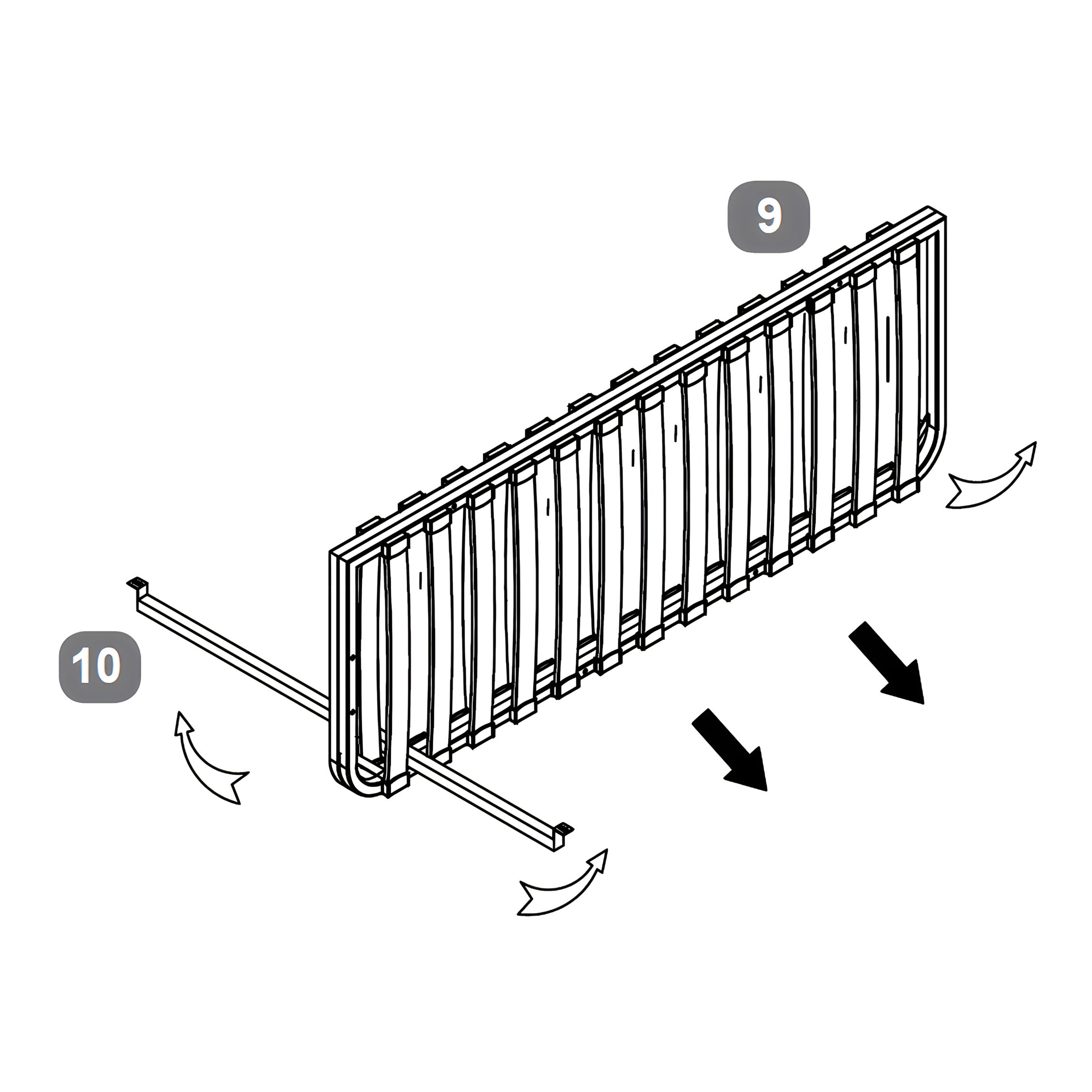
7. Prepare the Slat Frame and Cross Bar
1. Locate the Slat Frame Cross Bar (10) and insert it through the Metal Slat Frame (9), positioning it between the first and second slats as indicated. 2. Ensure the bar is centered and aligned correctly with the frame. 3. Once in place, carefully unfold the slat frame, allowing it to open fully in preparation for the next step.
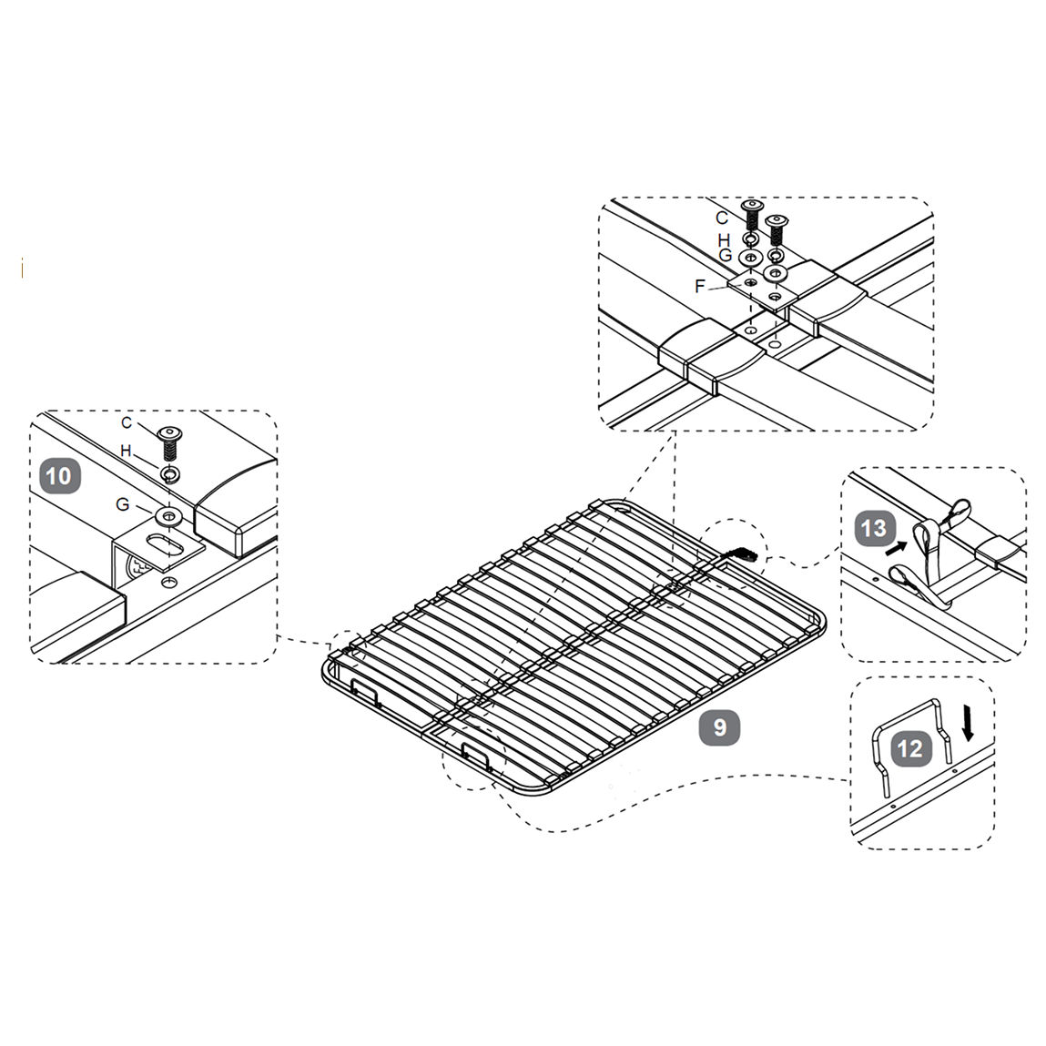
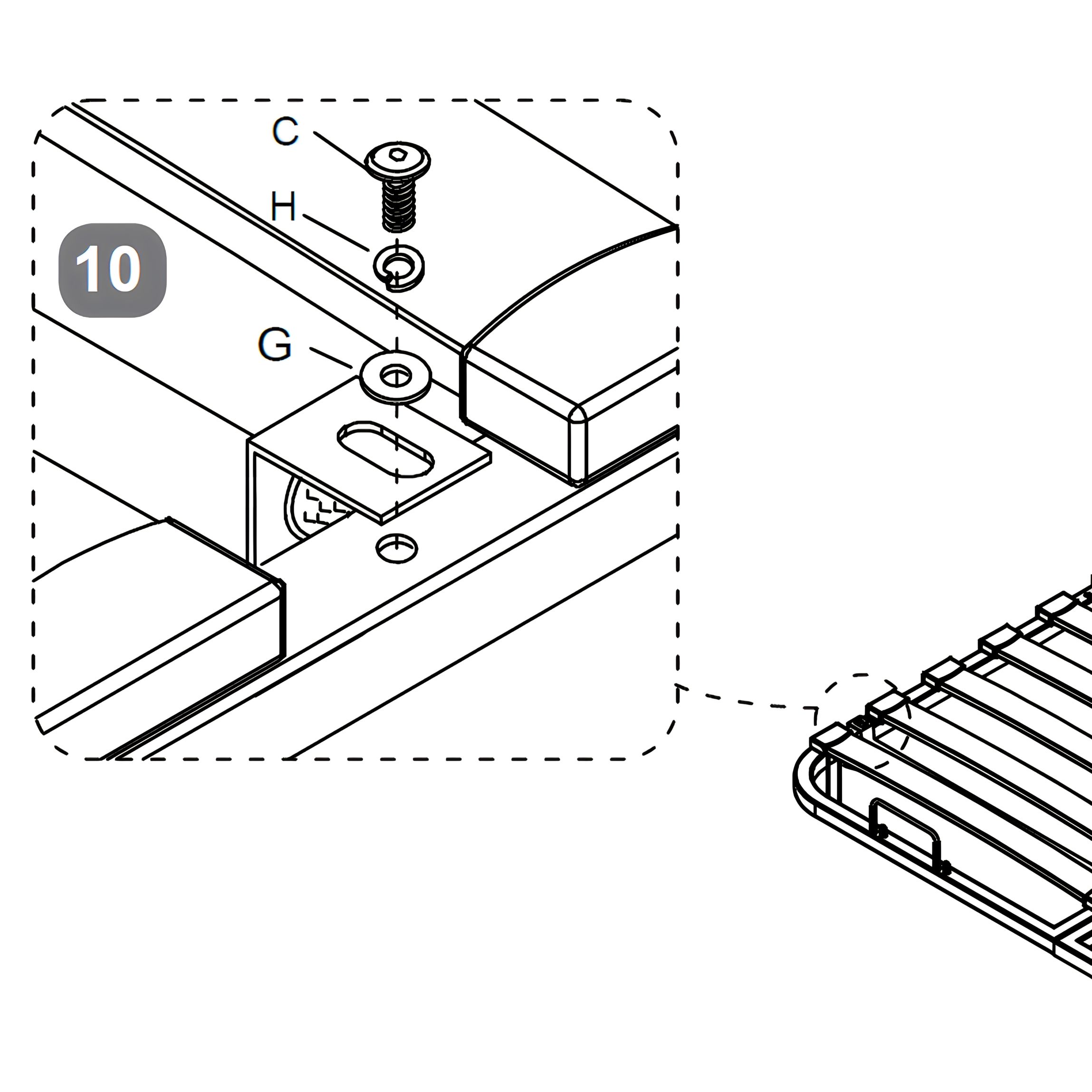
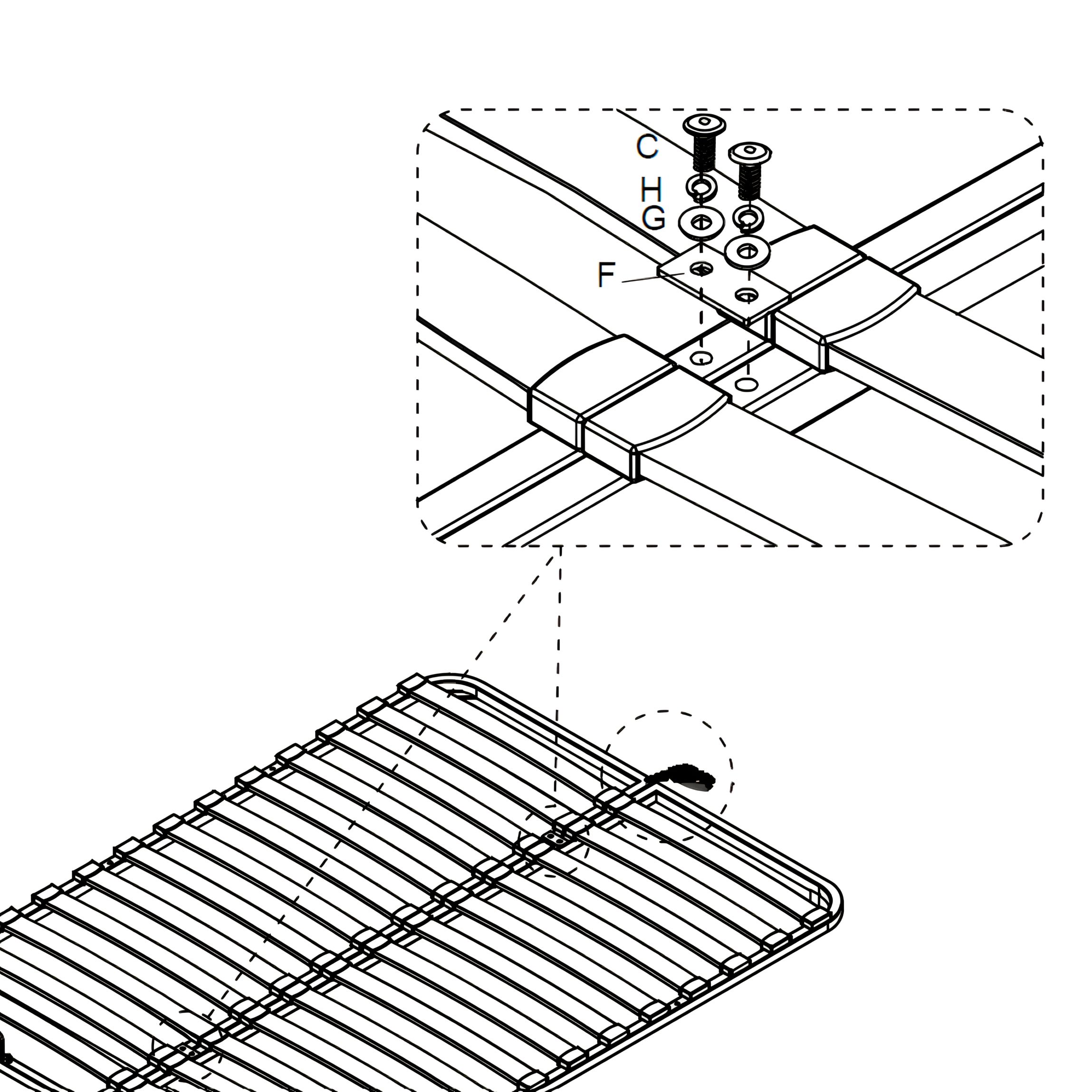
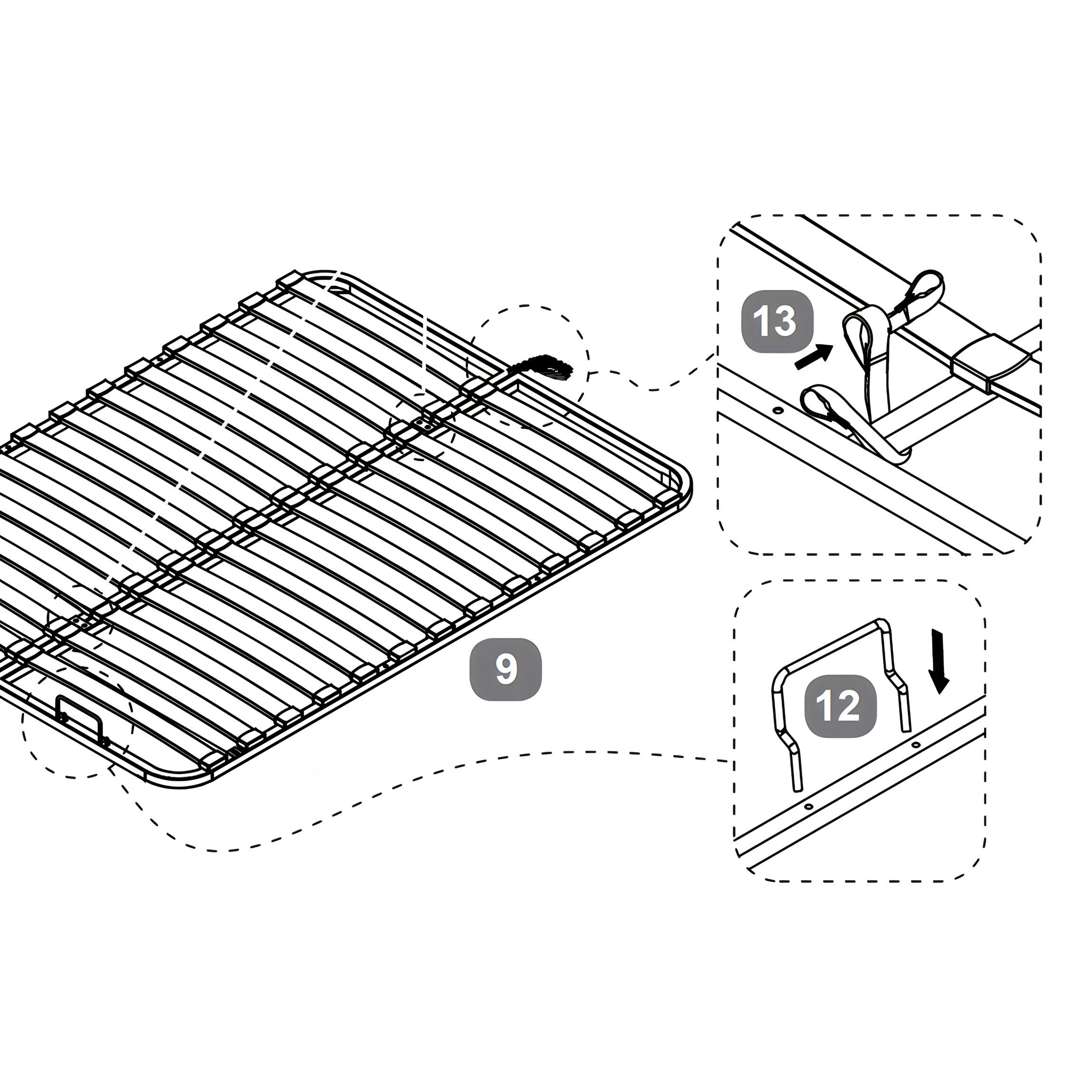
8. Assemble the Slat Frame
1. Lower the slat frame onto the Slat Frame Cross Bar (10). Align the mounting plates on the frame with the threaded inserts on the cross bar. 2. Loosely insert two sets of Bolts (M8x18mm) (C), Flat Washers (G), and Spring Washers (H) through the plates and into the inserts, do not tighten yet. 3. Position the Metal Connection Plates (F) across the slat frame joints. Use four additional sets of Bolts (C), Flat Washers (G), and Spring Washers (H) to secure them. 4. Once all components are in place, use the Allen Key (J) to tighten all six bolts fully and lock the frame to the structure. 5. Insert the Mattress Stoppers (12) into the pre-drilled holes at the foot end of the Metal Slat Frame (9) and press down until fully secured 6. Tie the Fabric Hand Strap (13) on the oppposite side of the Mattress Stoppers.
9. Install the Gas-Lift Pistons
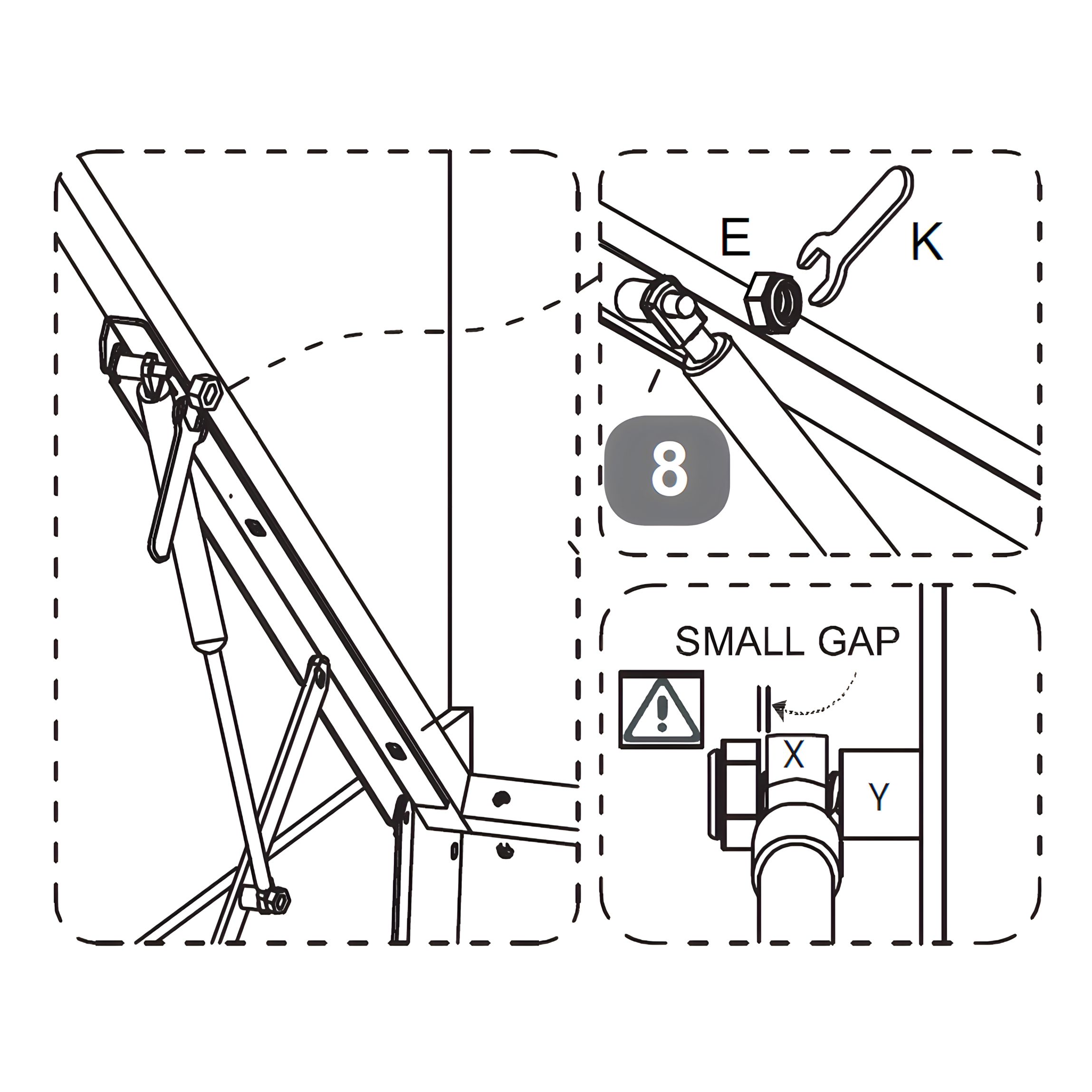
1. Slide the stem of the Gas-lift Piston (8) (X) onto the axle (Y) of the gas-lift mechanism. 2. Secure it in place using a Flanged Lock-Nut (E) and tighten it with the Spanner (K), do not over-tighten. 3. Repeat the process on both sides.
Important: Leave a small gap between the piston stem and the mounting bracket to allow free movement, as shown in the sketch. This ensures the mechanism operates smoothly.
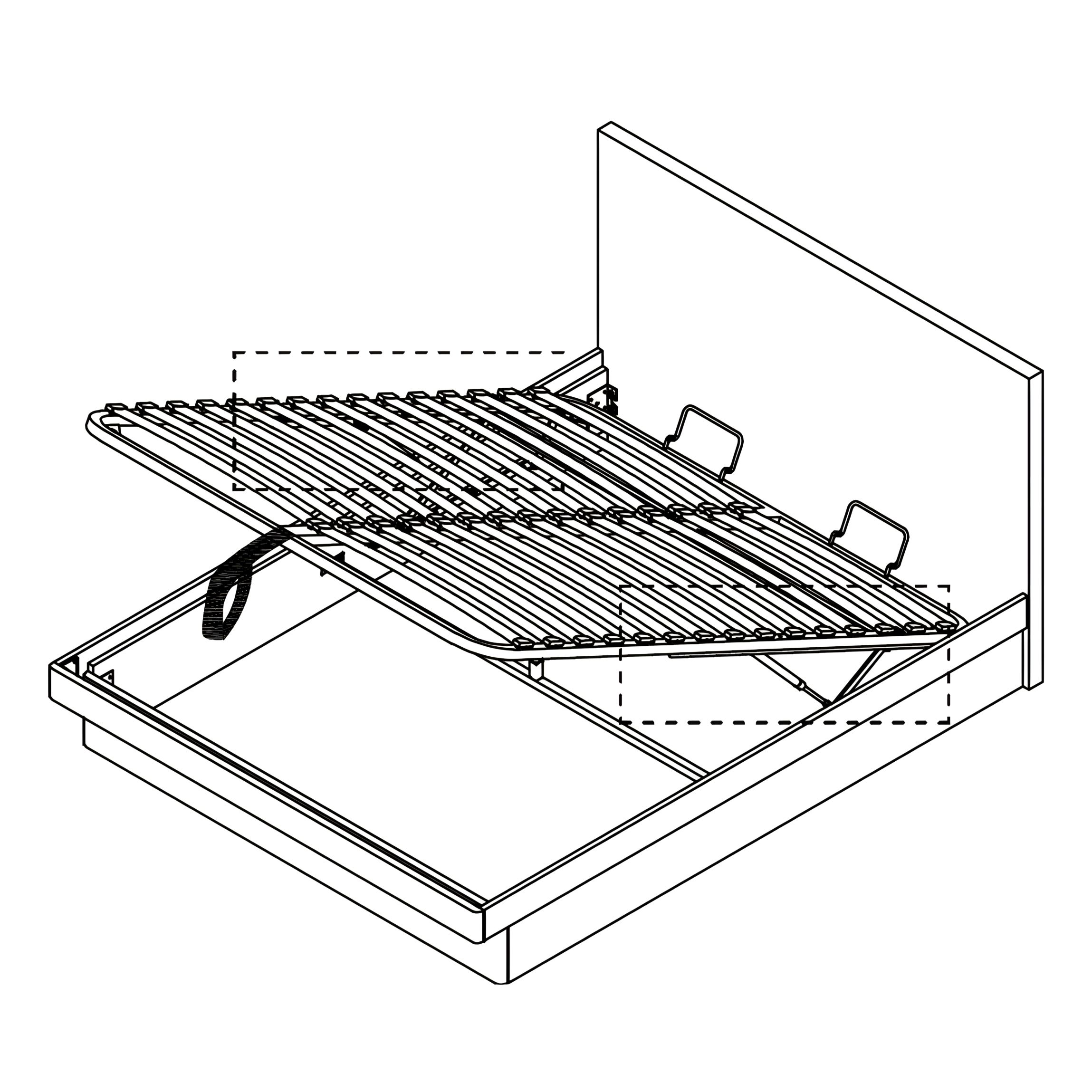
10. Secure the Slat Frame to the Gas-Lift Mechanism
1. Loosely insert three bolt sets on each side to connect the Metal Slat Frame (9) to the gas-lift mechanisms. 2. Use a Bolt (M8x45mm) (A), 2× Flat Washers (G), Spring Washer (H), and Nut (D) to attach them. 3. Use the Allen Key (J) and Spanner (K) to assist with assembly, but do not fully tighten yet. 4. Carefully lower the slat frame and adjust it so the side gaps are even on both sides. 5. Once the frame is aligned, tighten all bolts 100% to complete the structure.
11. Secure the Gas-Lift Pistons to the Slat Frame
1. Slide the stem of the Gas-lift Piston (8) (X) onto the axle (Y) on the underside of the Metal Slat Frame (9). 2. Fit the Flanged Lock-Nut (E) and tighten it using the Spanner (K) — do not over-tighten. 3. Repeat this process for both pistons.
Important: A small gap must be left between the piston stem and the bracket to ensure the piston can move freely. Refer to the diagram to confirm correct spacing.
12. Final Checks and Safety Precautions
1\. Storage Area Safety
Ensure the ottoman is fully open before accessing the storage space.
Avoid reaching through the hinge area to prevent injury.
Keep children and pets away from the bed when it is open.
Do not stand or climb inside the internal storage compartment.
Regularly inspect the bed mechanism to ensure it is functioning safely and smoothly.
2\. Operating Instructions
The gas-lift mechanism is intended for adult use only. It is not suitable for users under 12 years old.
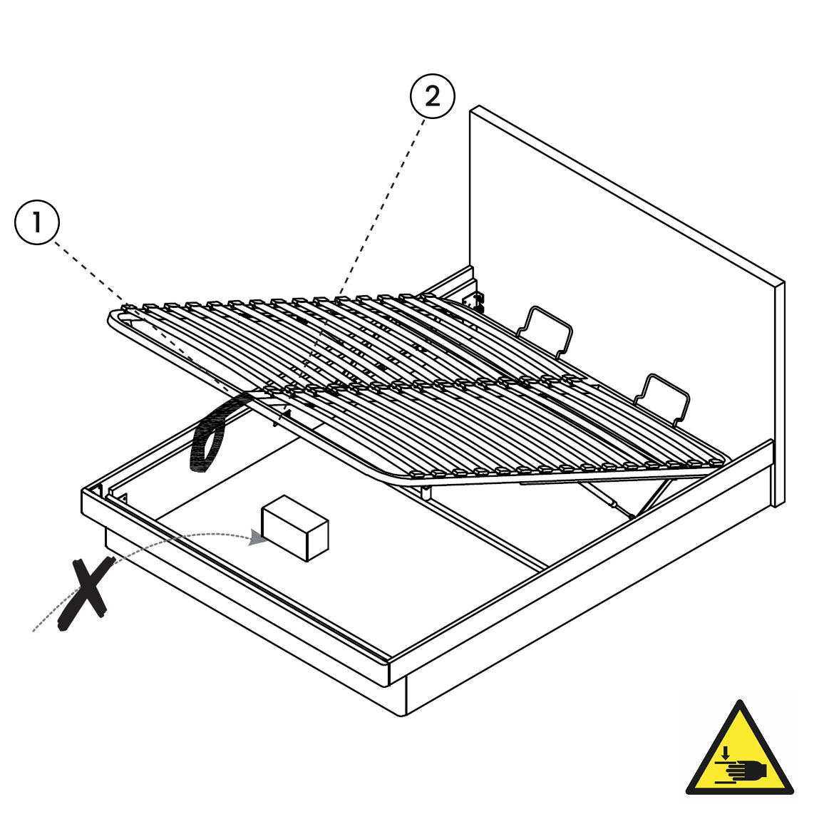
Always lift the ottoman with the mattress in place, using the fabric hand strap (13) to raise and lower the base.
Keep hands and body clear of the lifting mechanism during operation to avoid entrapment.
Note: Be mindful of what you store under the bed. Items such as suitcases or boxes must not touch the underside of the slat frame, as this may cause damage.