Assembly instructions for the Miami 3 Drawer Dressing Table Including Mirror
Product Information
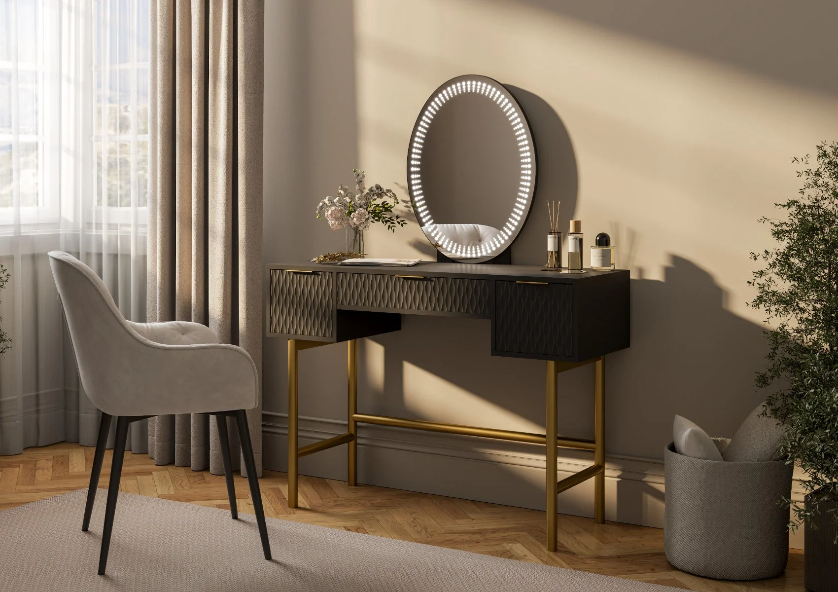
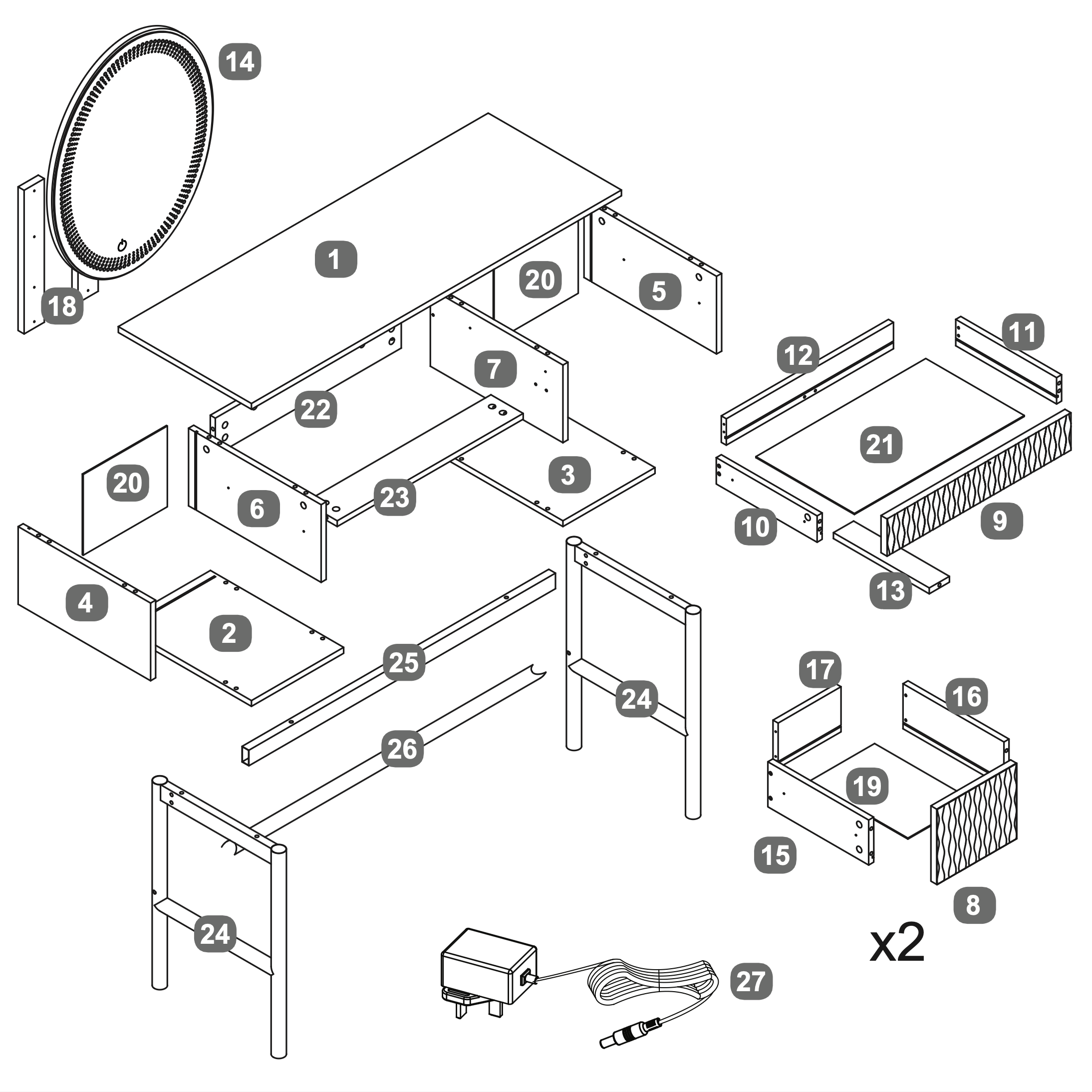
Miami 3 Drawer Dressing Table Including Mirror
Looking to transform your beauty space? Create that high end contemporary hotel bedroom look with our luxurious Miami black 3 drawer dressing table. Shown here in a stunning black finish with contrasting gold handles and legs this dressing table is sure to make a stylish addition to any bedroom.
The LED mirror offers adjustable lighting ensuring the perfect ambiance for your makeup and skincare routine. With spacious drawers the dressing table provides ample storage for all your beauty and styling essentials, keeping your space organised and clutter free. The attractive sculptured drawer fronts add a sense of style and sophistication.
Mirror Dimensions - 47.8cm x 60cm x 20cm and comes in 3 colour choices: Black Gold, White Gold or White Silver.
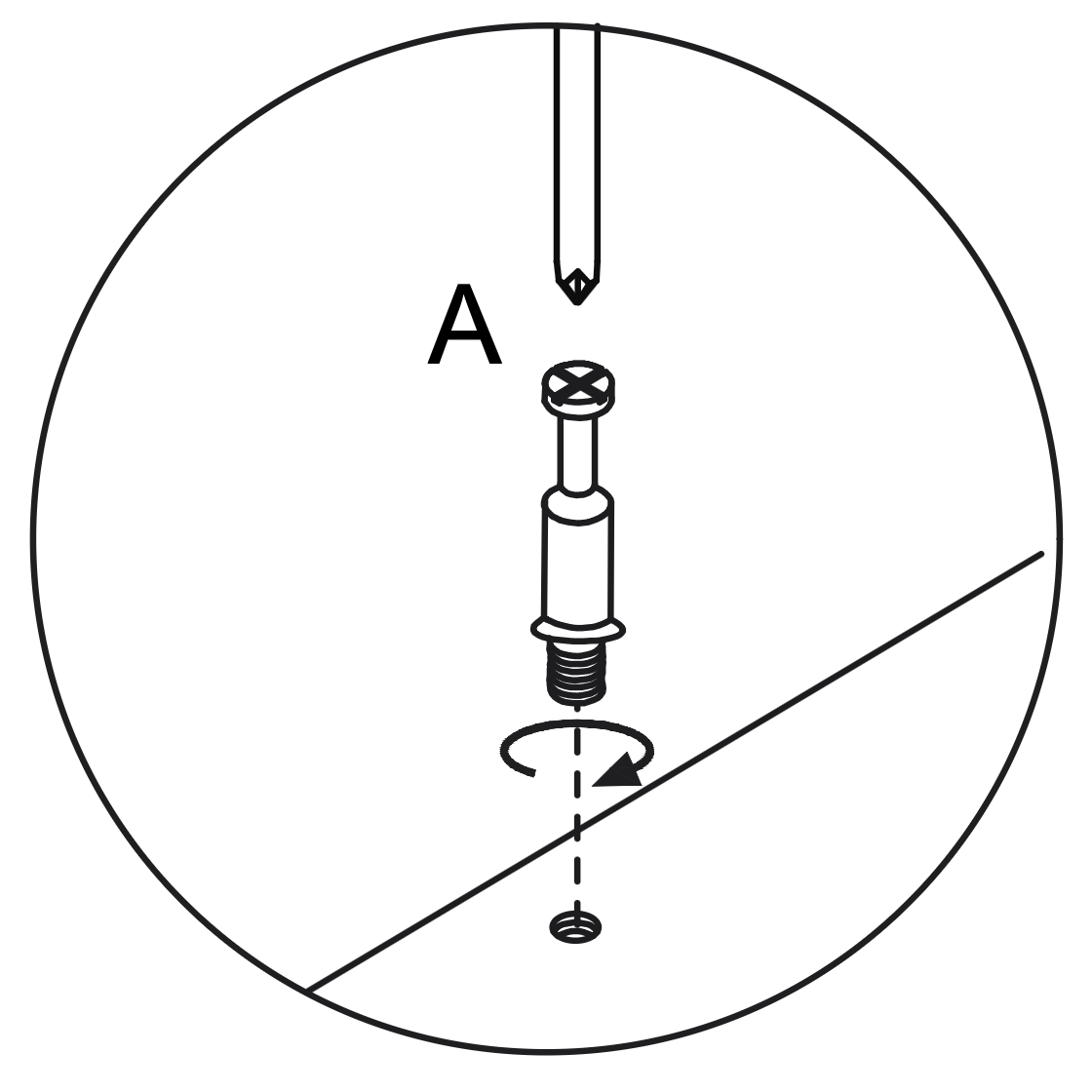
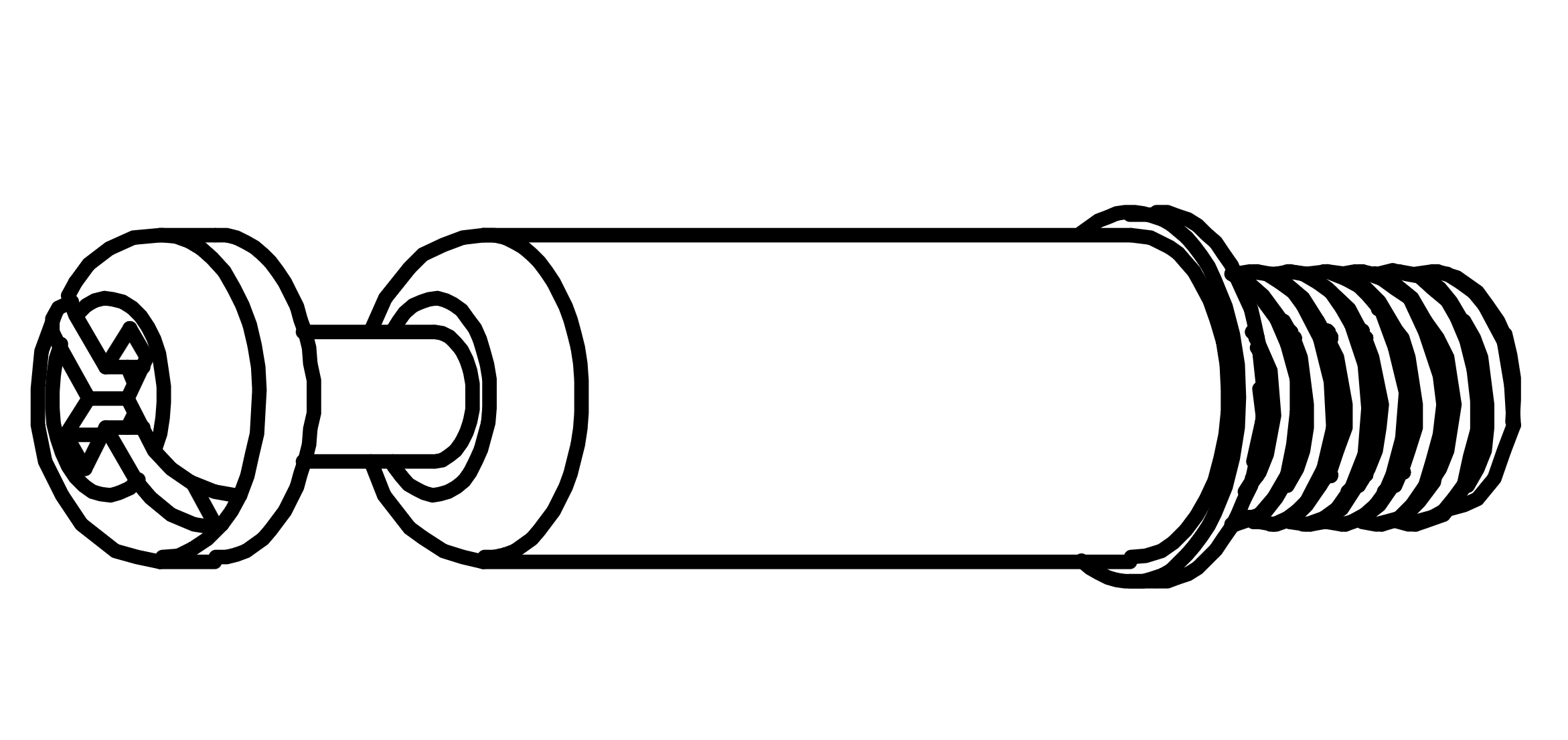
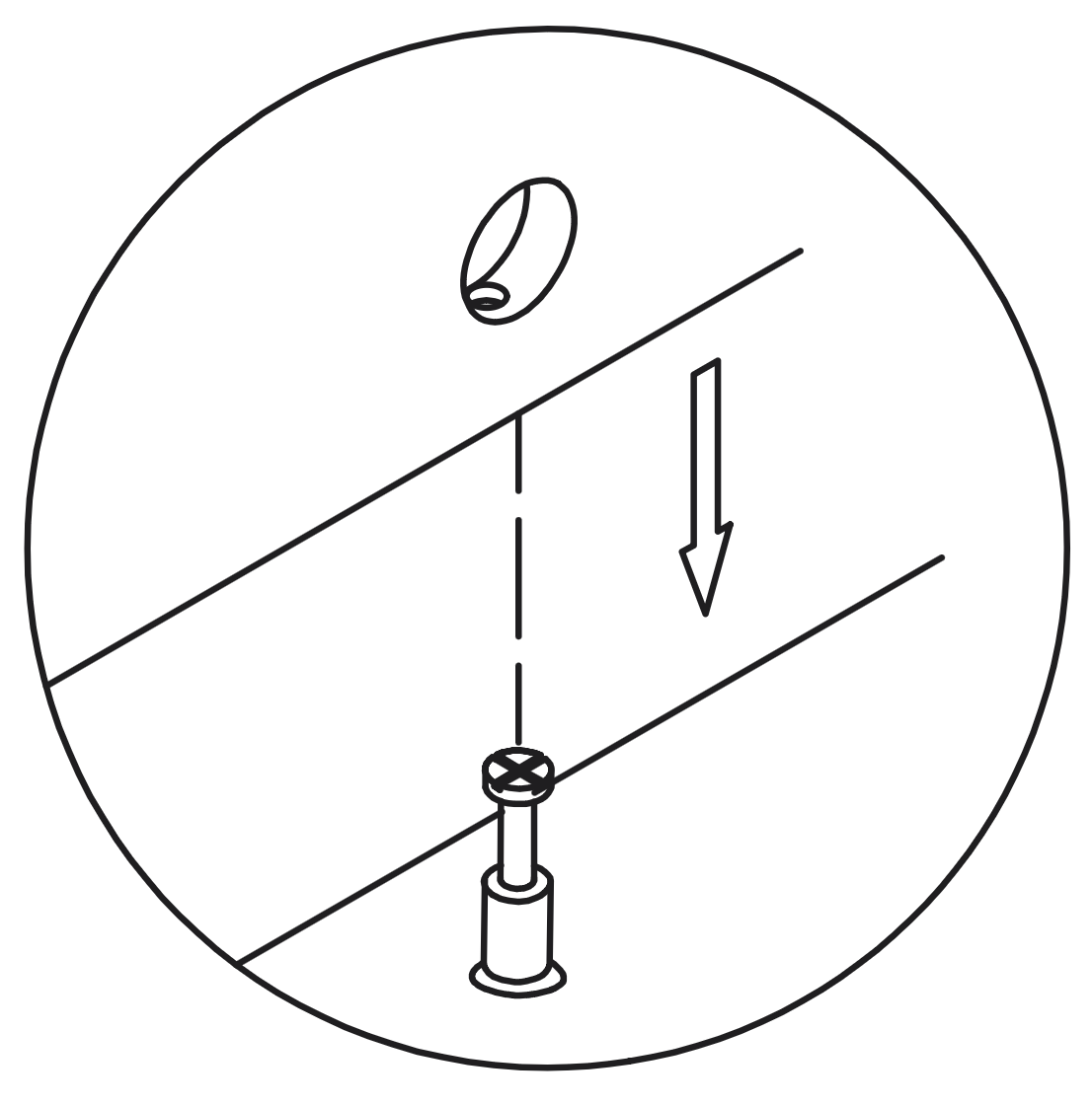
Insert the Cam Dowel (A) into the designated hole on the panel.
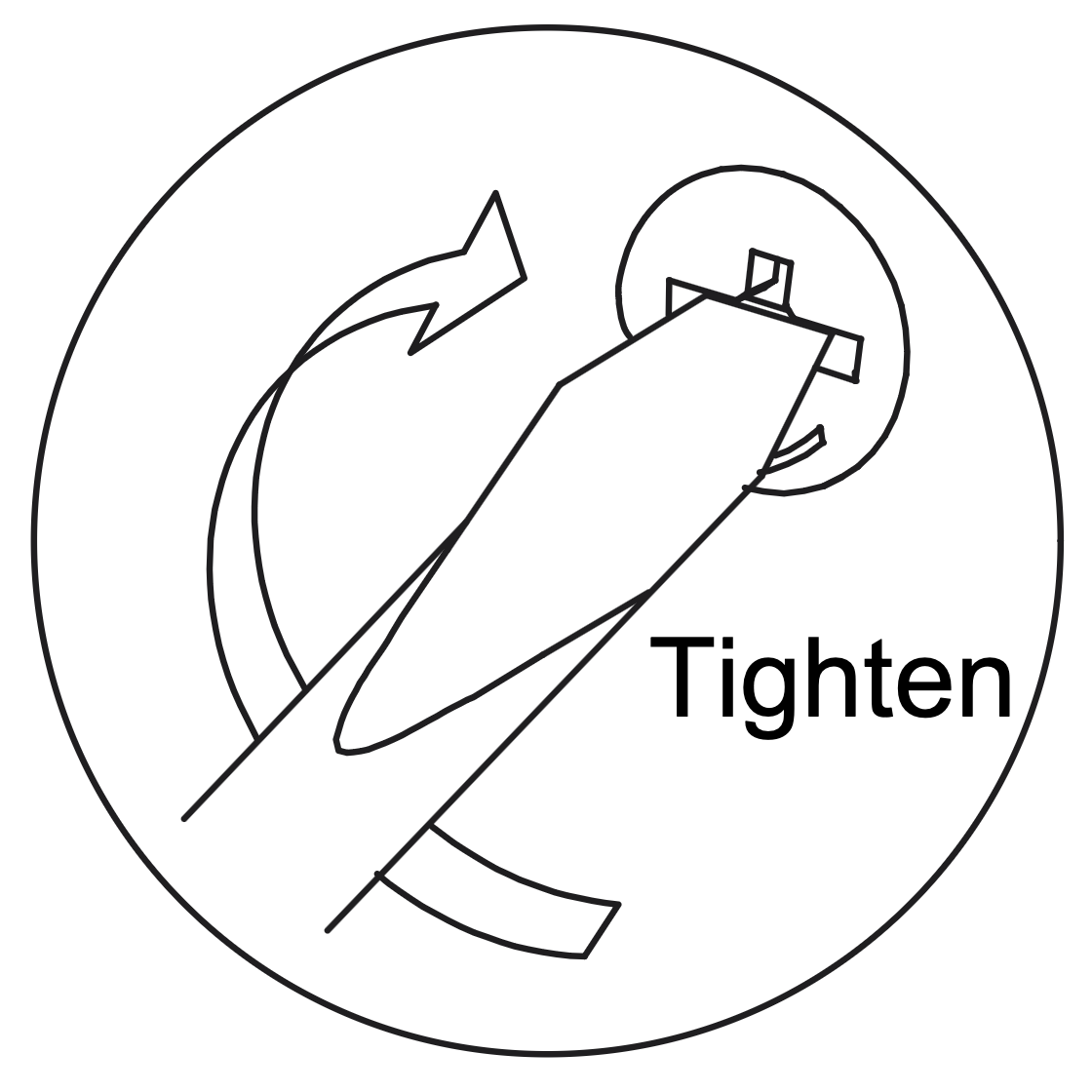
Use a screwdriver to turn the dowel clockwise until it is fully inserted and level with the surface, ensuring it extends 35mm above the panel.
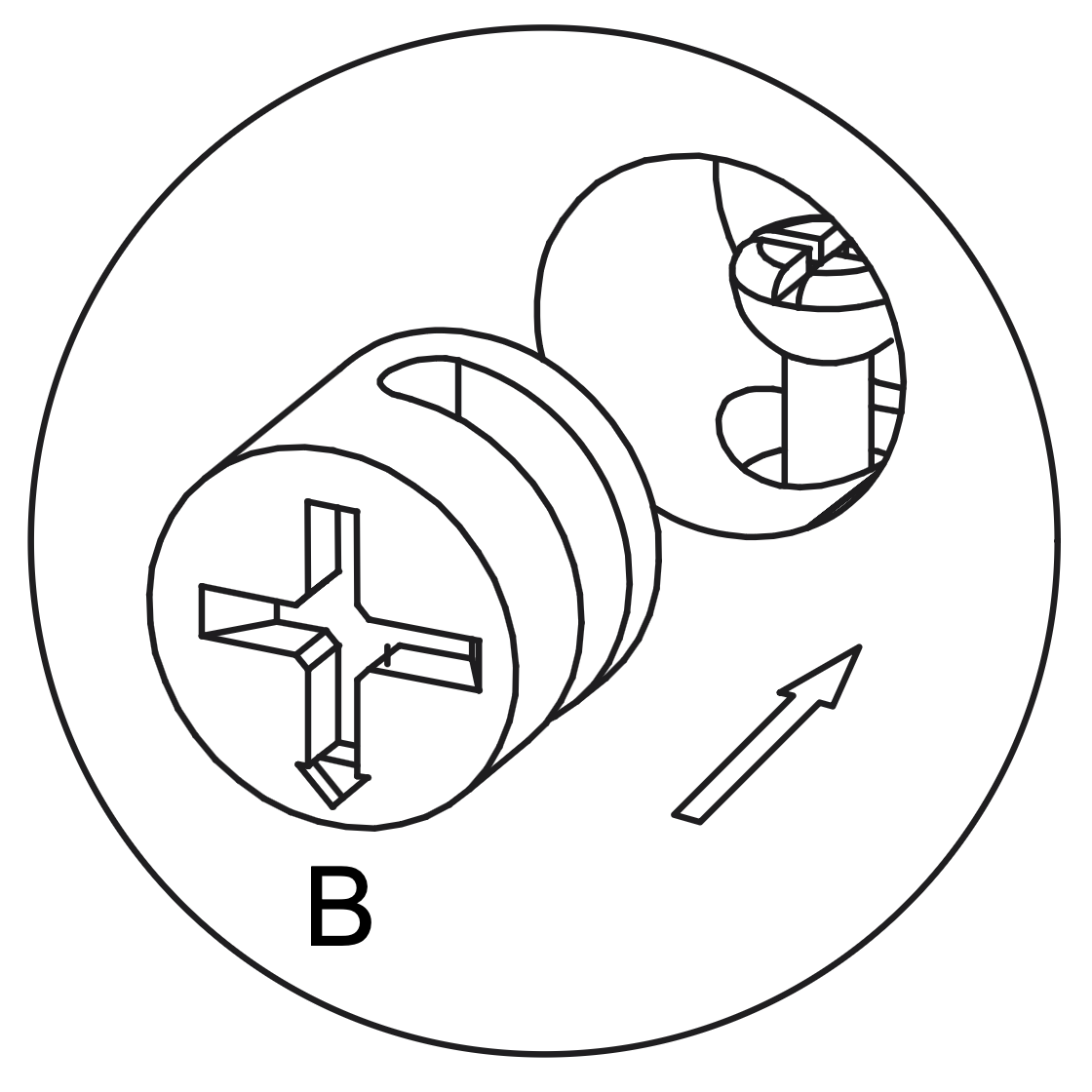
2. Working with Cam Locks
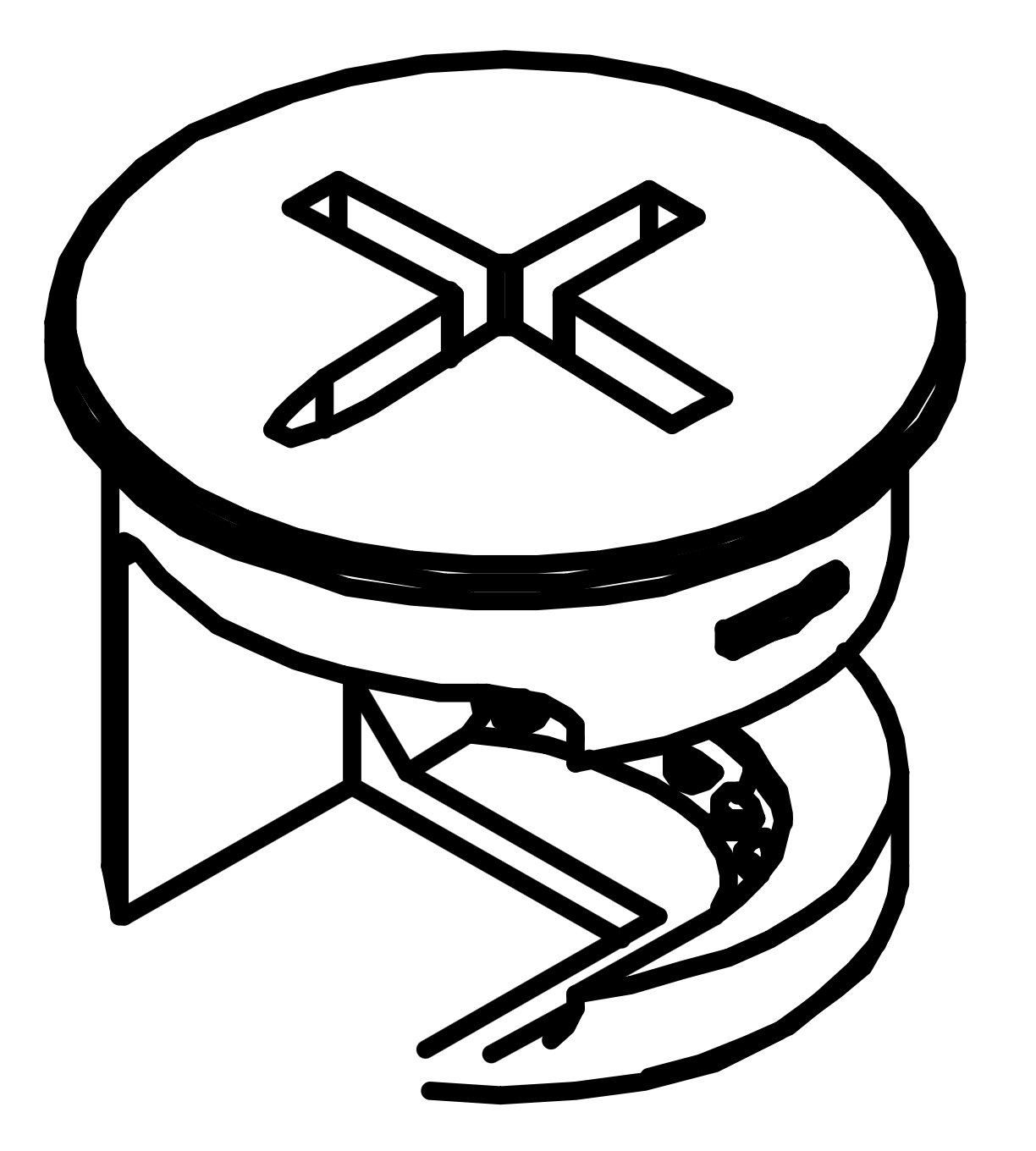
Insert the Cam Lock (B) into the designated hole on the panel, aligning it with the Cam Dowel (A).
Use a screwdriver to turn the Cam Lock clockwise until it is securely tightened, ensuring a firm connection between the panels.
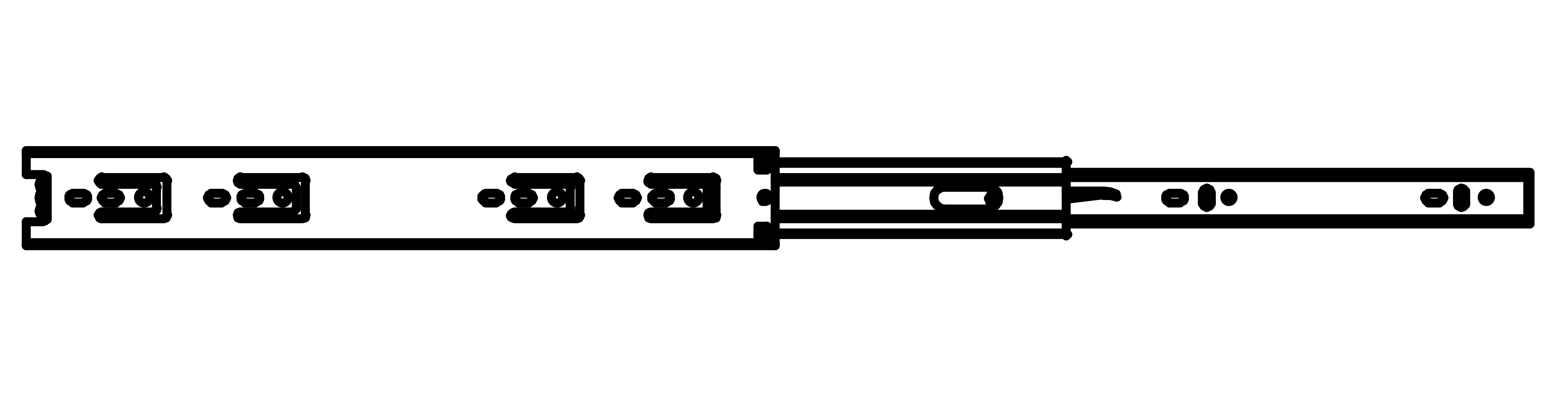
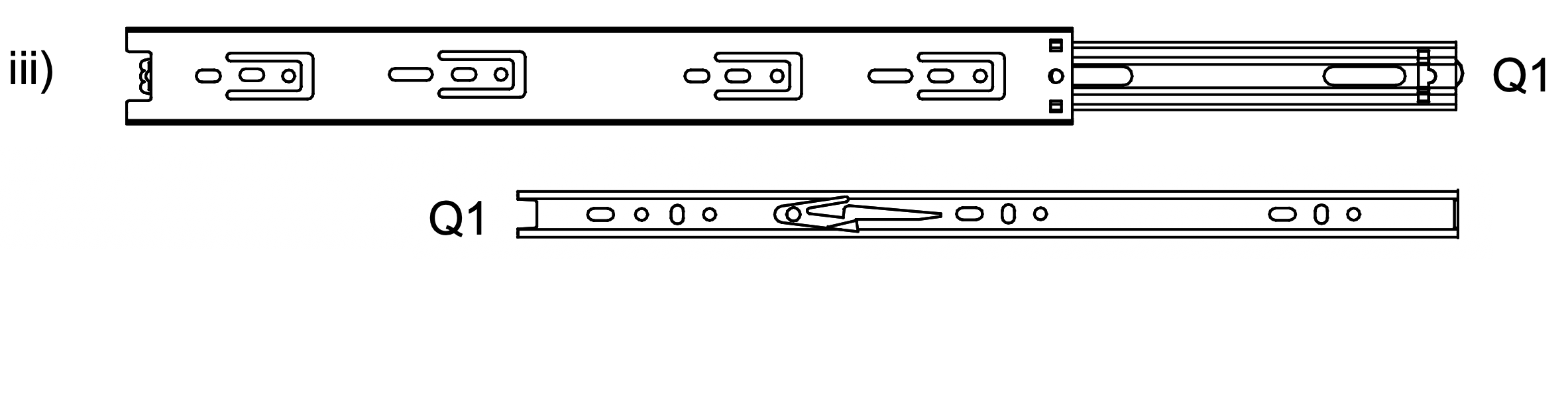
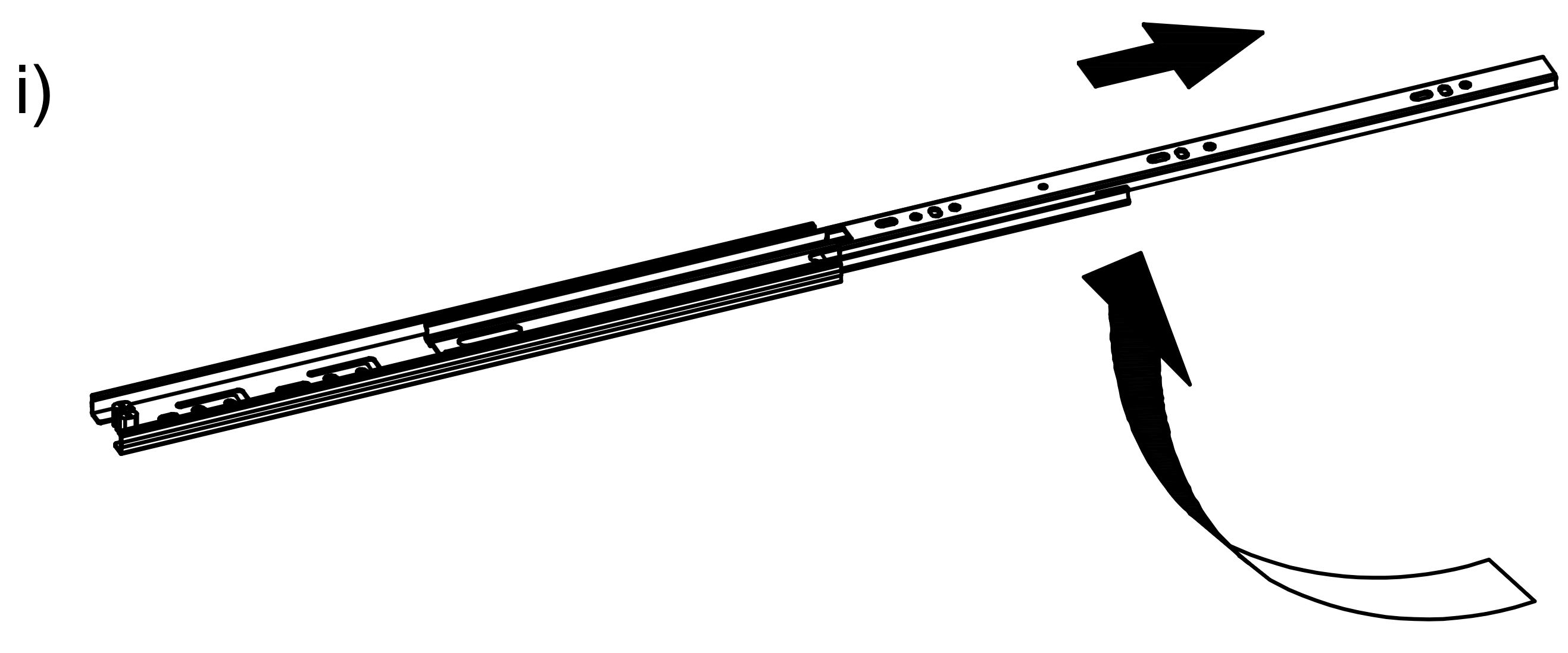
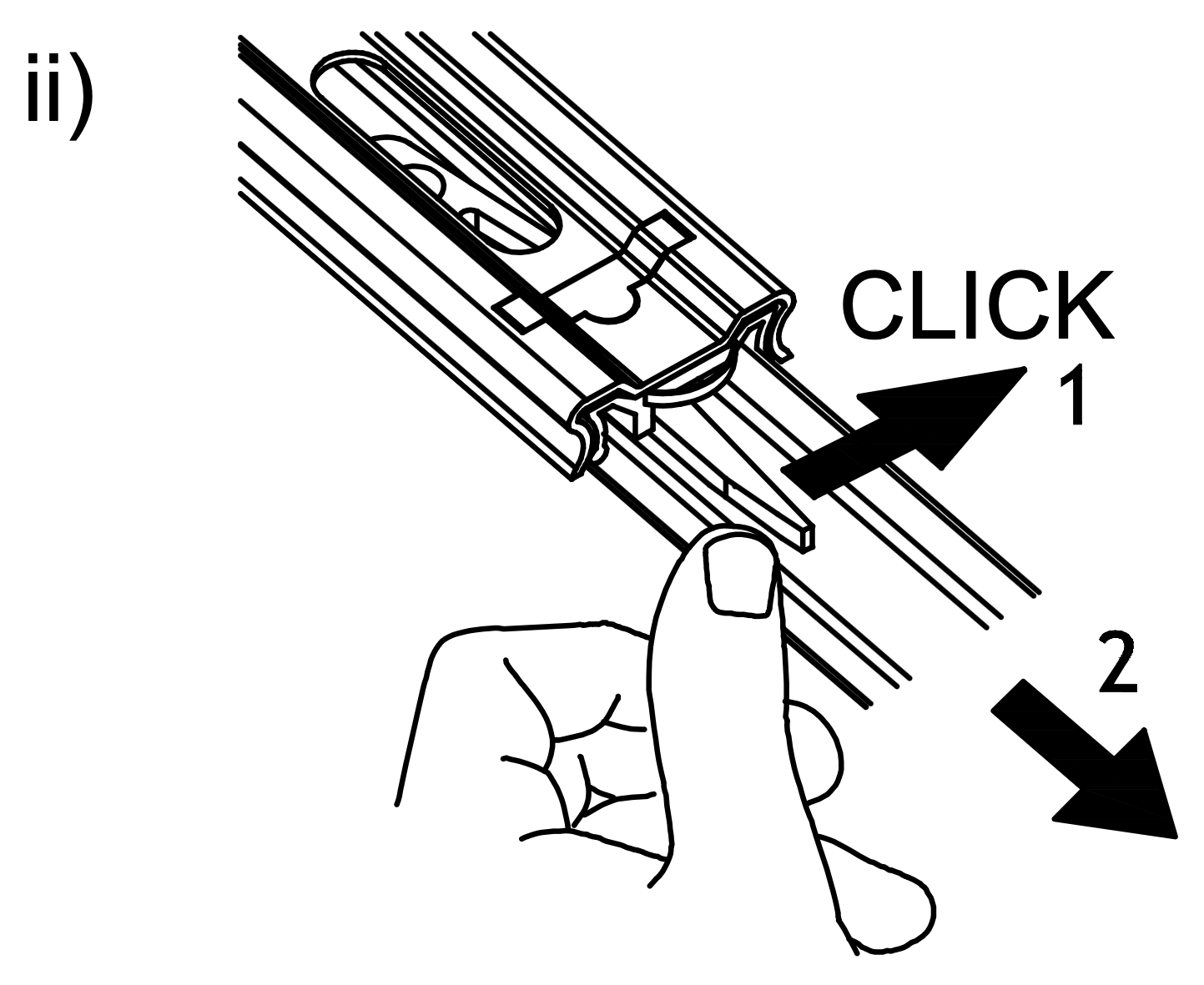
3. Separate the Runner
1. Extend the Runner (Q) by pulling it outwards as shown in the first image. 2. Press the release lever on the runner to separate the two parts, ensuring a "click" sound is heard to confirm detachment. 3. Identify the two parts of the Runner (Q1) and prepare them for installation on the drawer and the side panel.
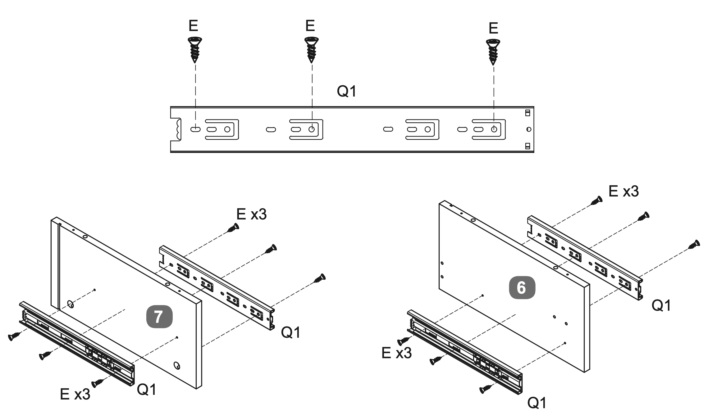
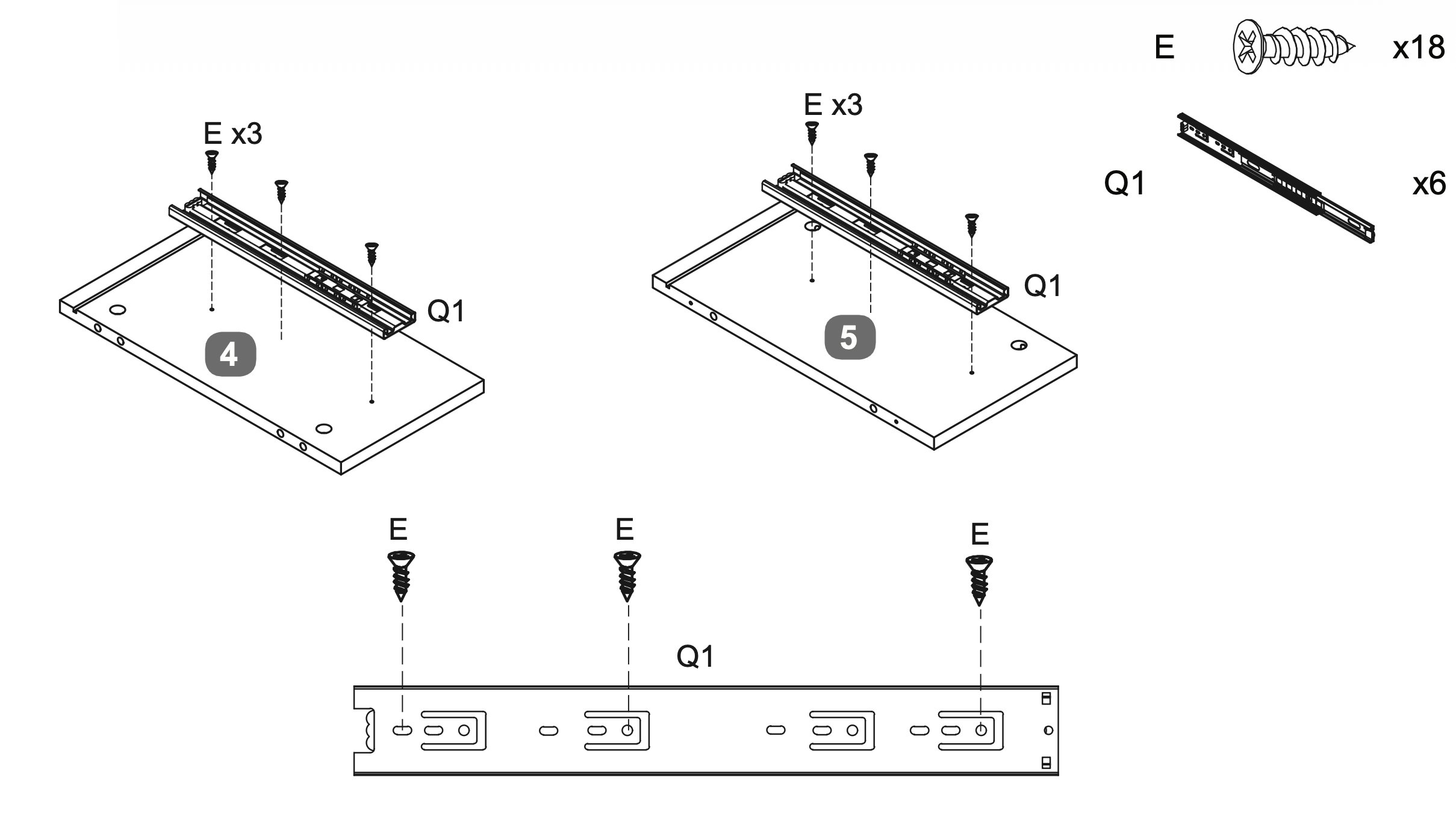
4. Attach and Secure Drawer Runners
Attach the Runner (Q1) to the drawer panels by aligning it with the pre-drilled holes.
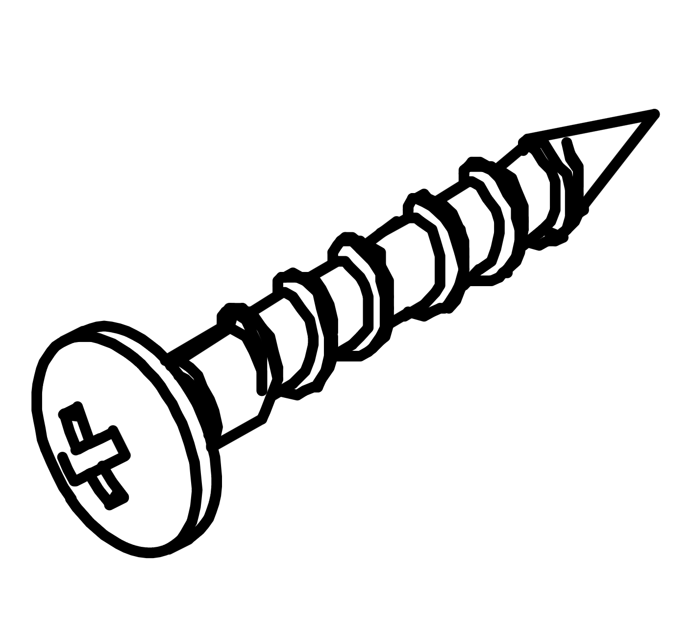
Secure each runner using three Screws (E).
Repeat this process for all drawer panels, ensuring the runners are firmly attached and aligned correctly for smooth operation.
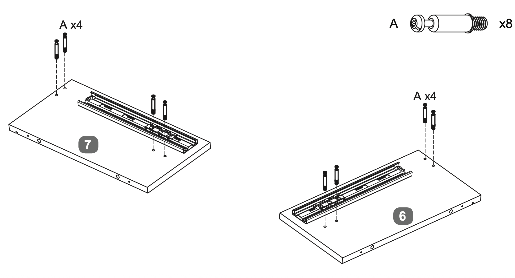
5. Insert and Secure Dowels
Insert four Cam Dowels (A) into the designated holes on each of the two panels labeled 6 and 7.
Use a screwdriver to turn each dowel clockwise until fully inserted and level with the surface, ensuring they extend 35mm above the panels.
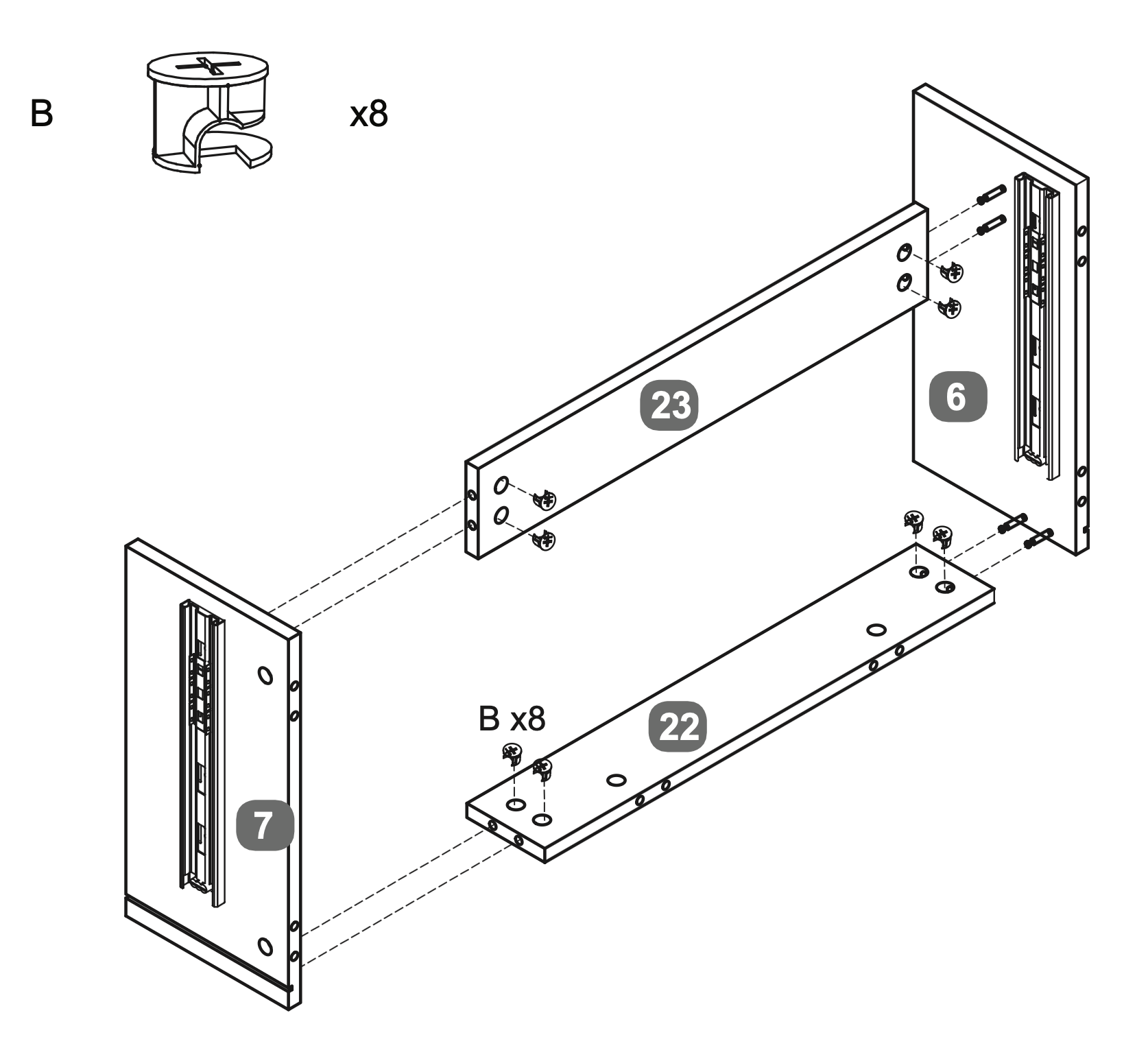
6. Align and Secure Cross Rails
Align the Centre Cross Rail (23) and Rear Cross Rail (22) between the LH Upright (6) and RH Upright (7).
Insert Cam Locks (B) into the designated holes on the cross rails.
Secure the cross rails by turning the Cam Locks clockwise with a screwdriver until tight, ensuring a firm connection between the Upright panels.
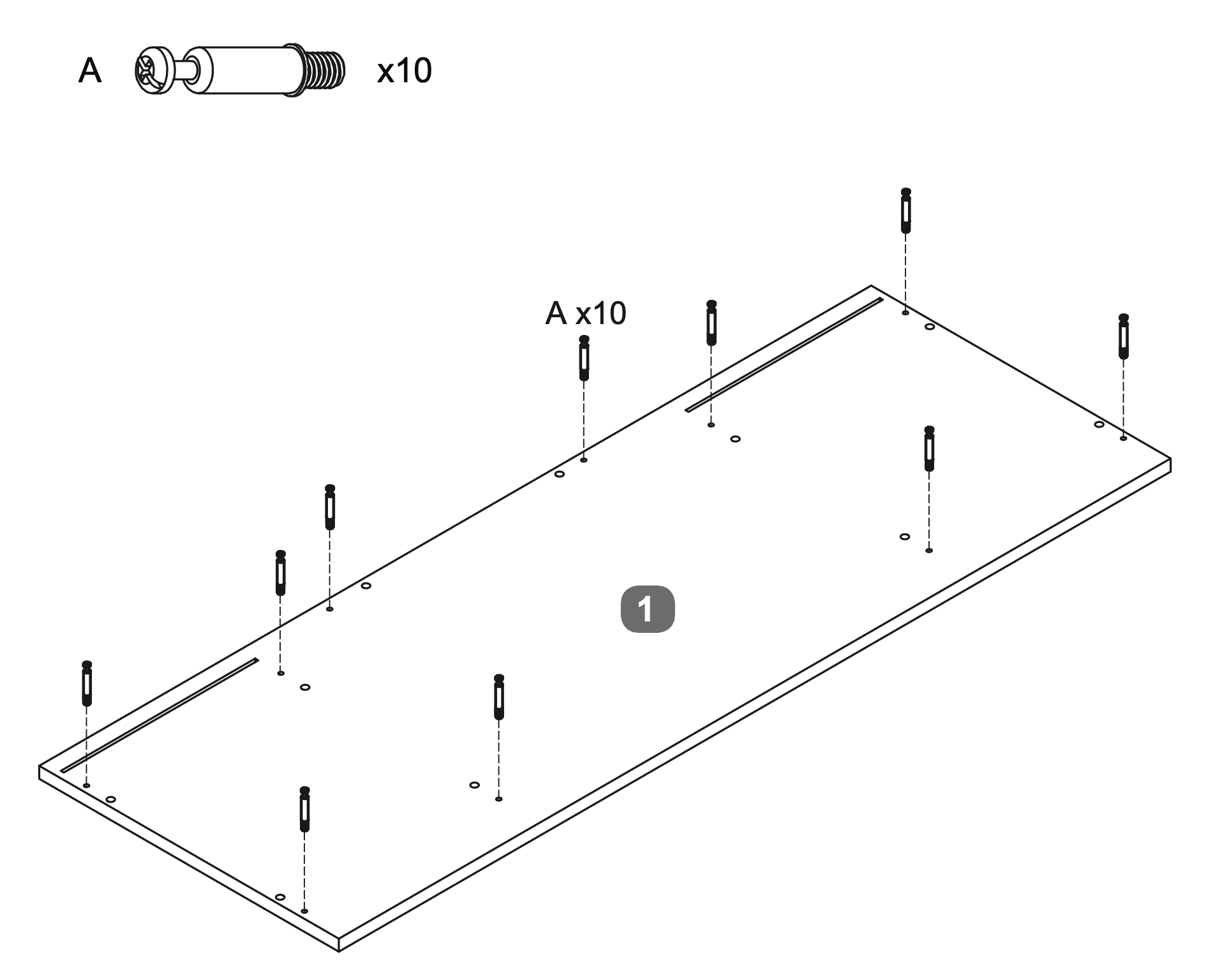
7. Dowel Insertion and Leveling
Insert ten Cam Dowels (A) into the designated holes on the Top Panel (1).
Use a screwdriver to turn each dowel clockwise until fully inserted and level with the surface, ensuring they extend 35mm above the panel.
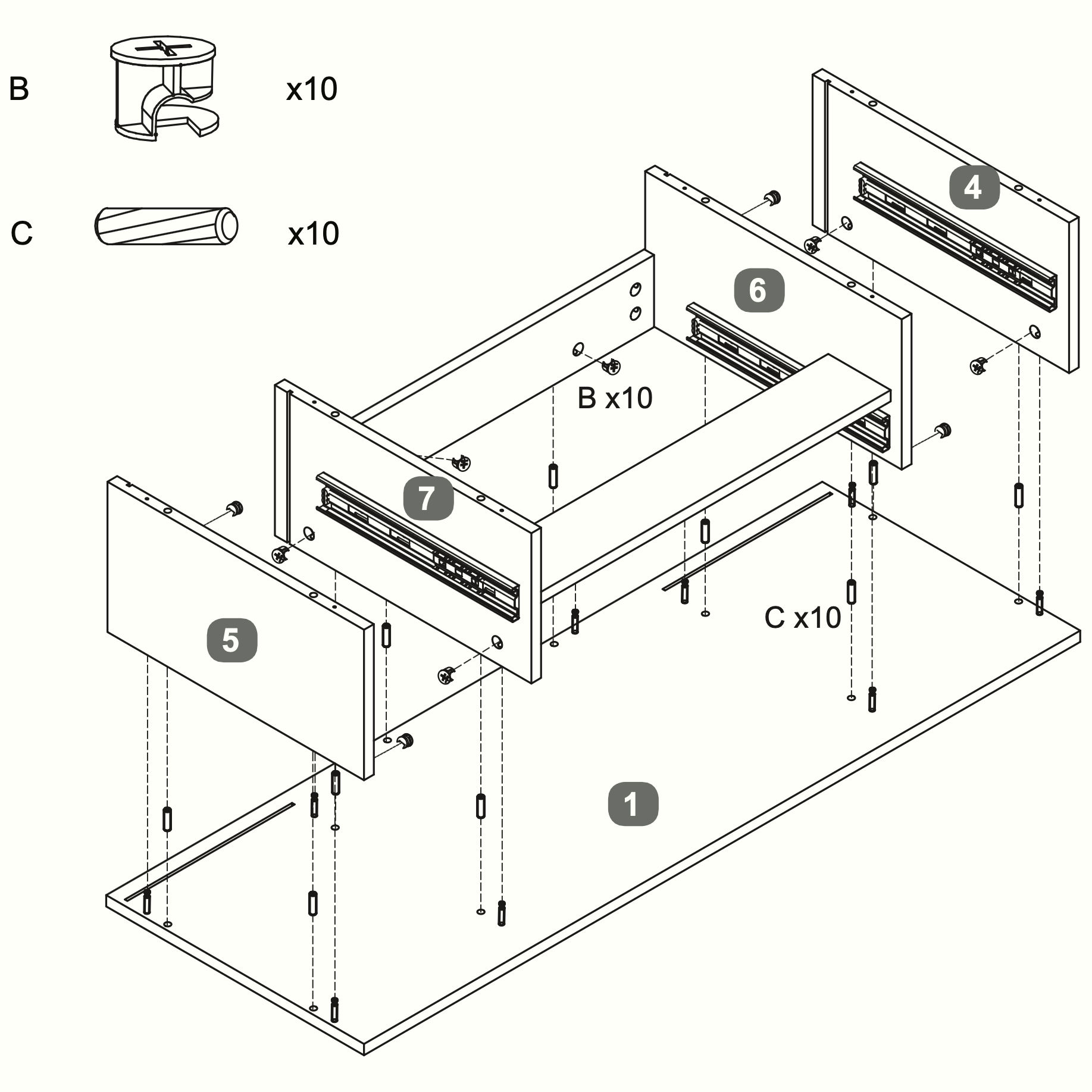
8. Panel Assembly and Securing
Insert ten Dowels (C) into the designated holes on the Top Panel (1).
Align the LH Upright (6) and RH Upright (7) with the Top Panel (1).
Insert the Cam Locks (B) (10 in total for this step) into the designated holes on the LH Upright (6) and RH Upright (7).
Secure the Upright panels by turning the Cam Locks clockwise with a screwdriver until tight, ensuring a firm connection.
Attach the RH Side Panel (5) and LH Side Panel (4) to the assembly, aligning them with the pre-drilled holes and completing the same steps as above.
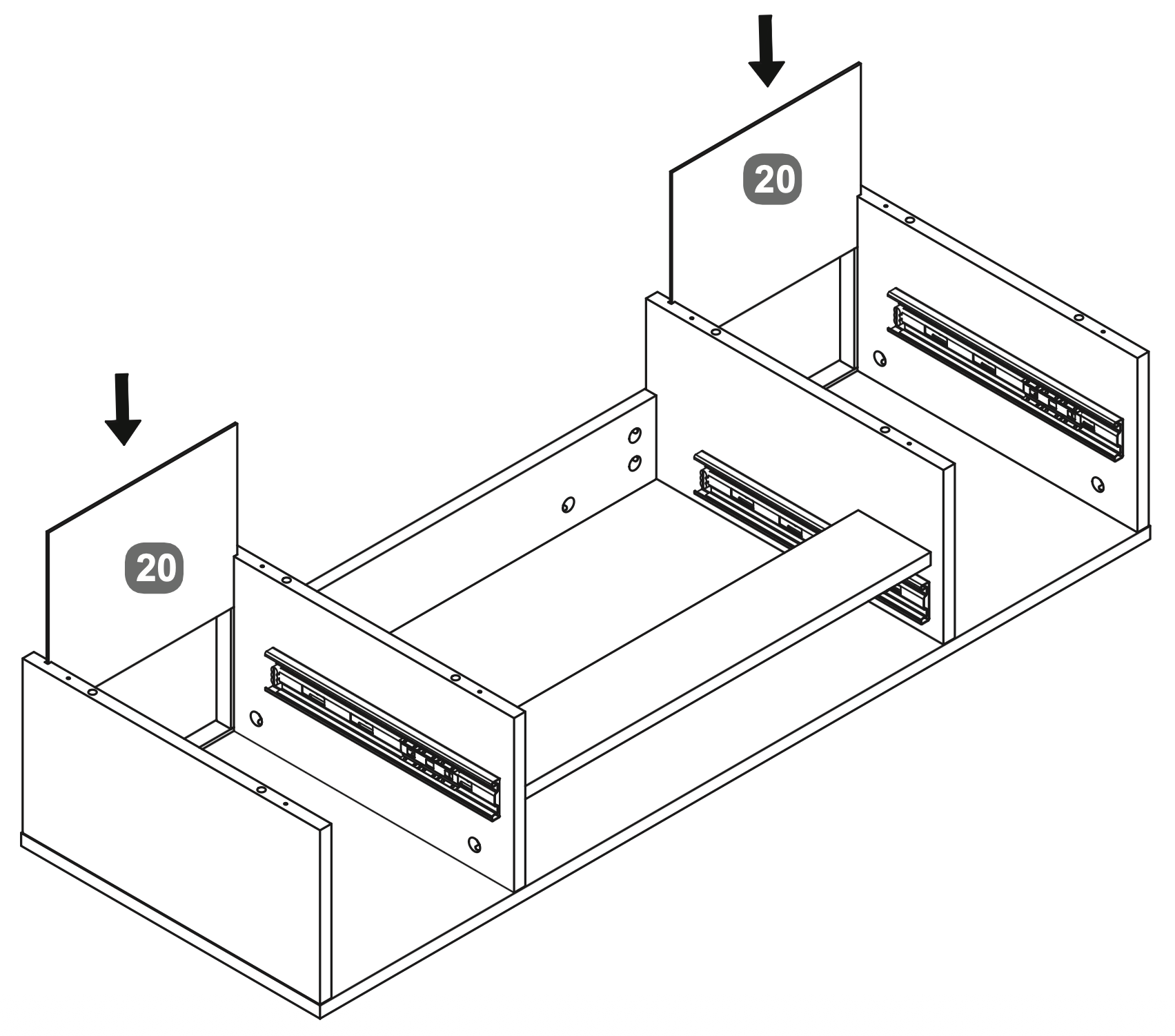
9. Rear Panel Installation
Insert the Back Panel (20) into the slots at the rear of the assembly, ensuring it fits securely between the side panels.
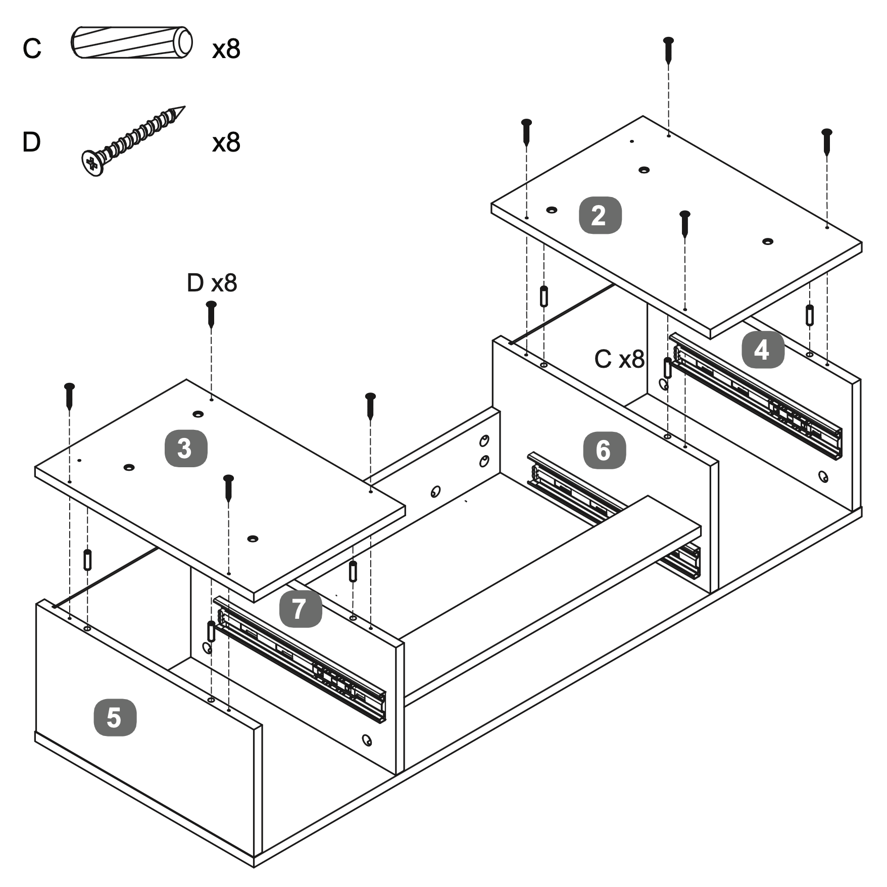
10. Panel Assembly and Fastening
Insert eight Dowels (C) into the designated holes on the SidePanels/Uprights (6, 7, 4 and 5).
Align the RH Base Panel (3) and LH Base Panel (2) with the SidePanels/Uprights (6, 7, 4 and 5).
Secure the panels using eight Screws (D), ensuring they are tightly fastened to maintain stability.
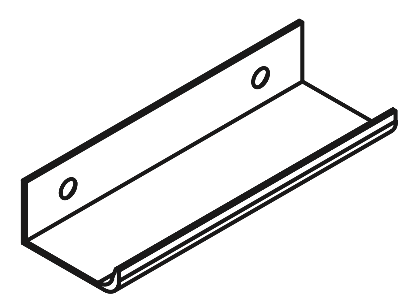
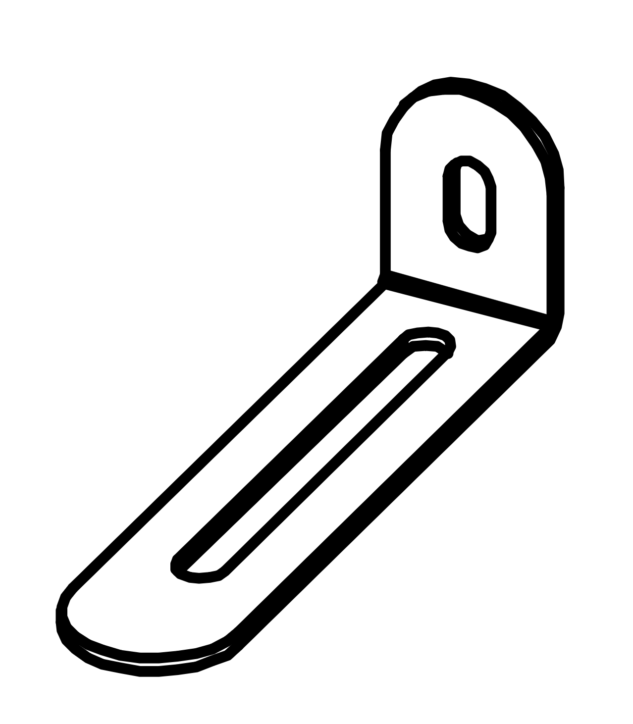
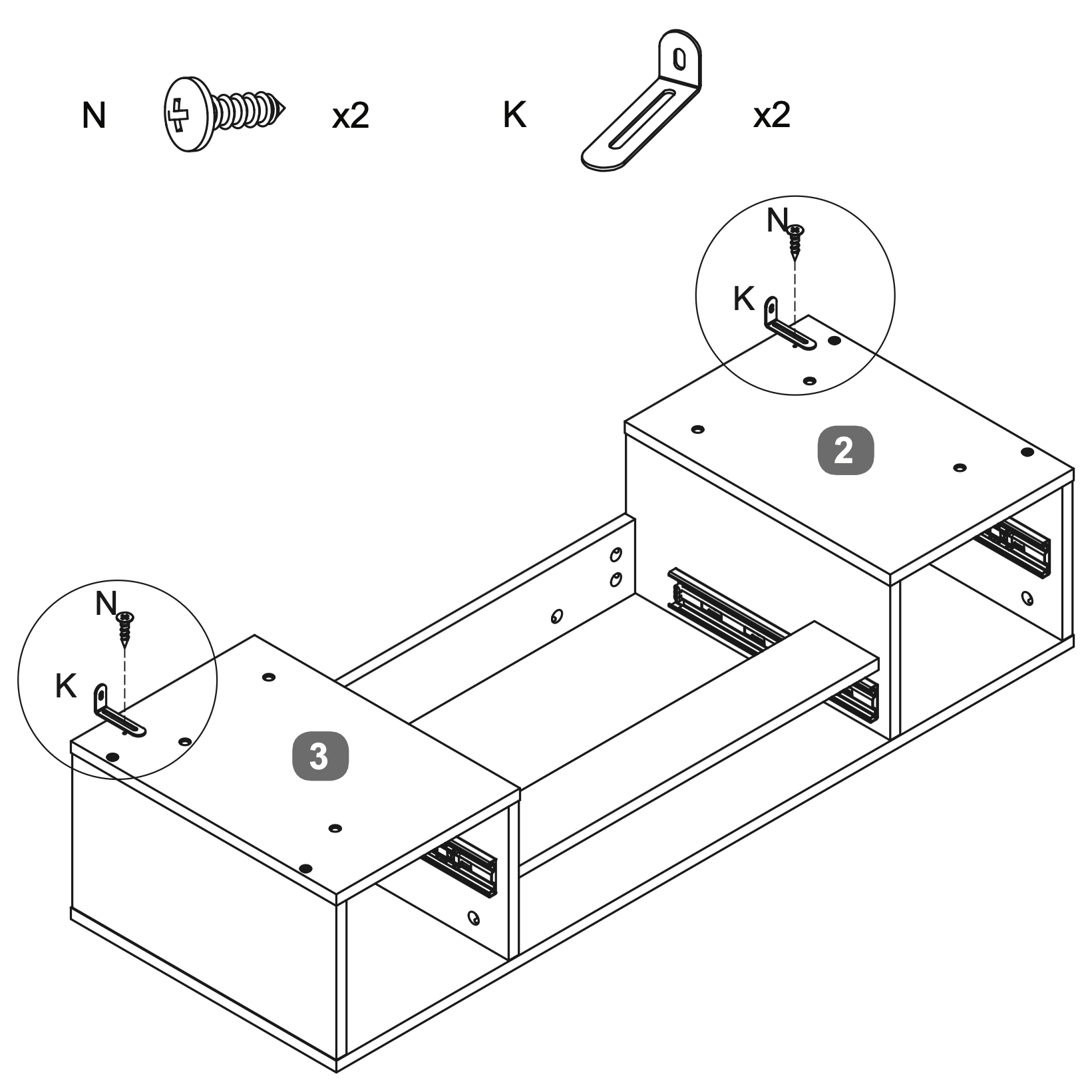
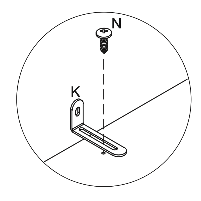
11. Bracket Installation and Stabilization
Attach two Metal Anti-tilt Brackets (K) to the top of the assembly, aligning them with the pre-drilled holes on the RH Base Panel (3) and LH Base Panel (2).
Secure each bracket using one Screw (N), ensuring they are tightly fastened for stability.
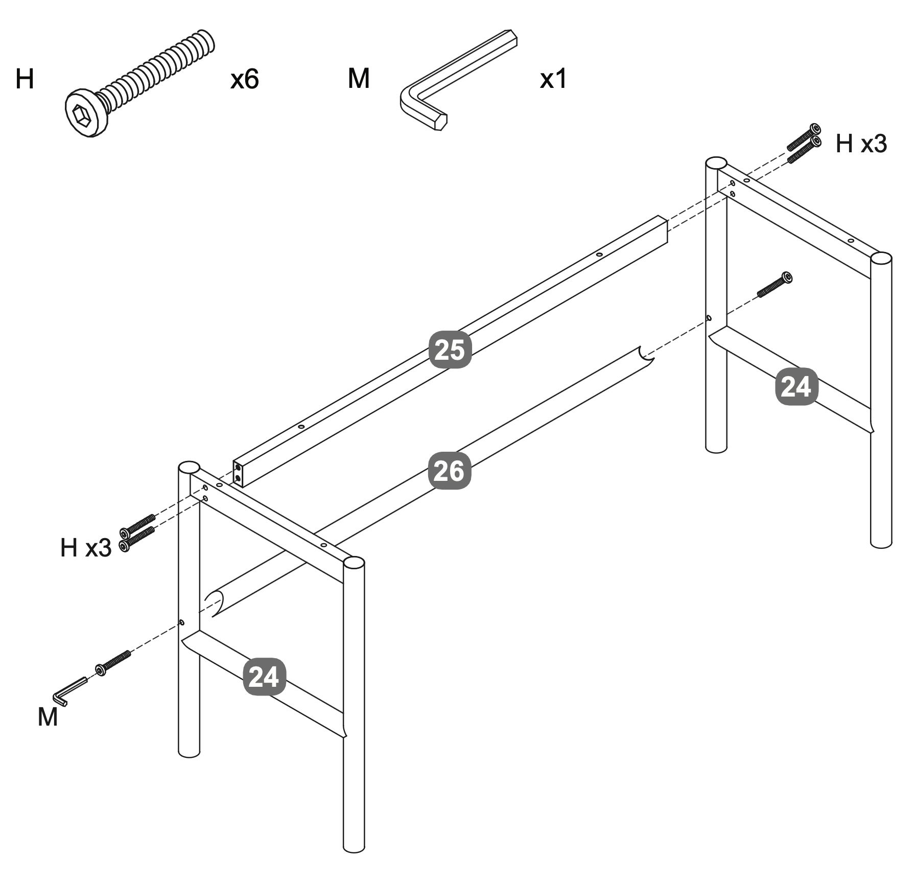
12. Frame Assembly and Fastening
Align the two Metal Leg Frames (24) vertically.
Position the Metal Cross Rail - Upper (25) and Metal Cross Rail - Lower (26) between the Metal Leg Frames (24).
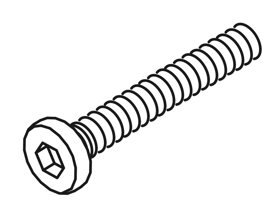
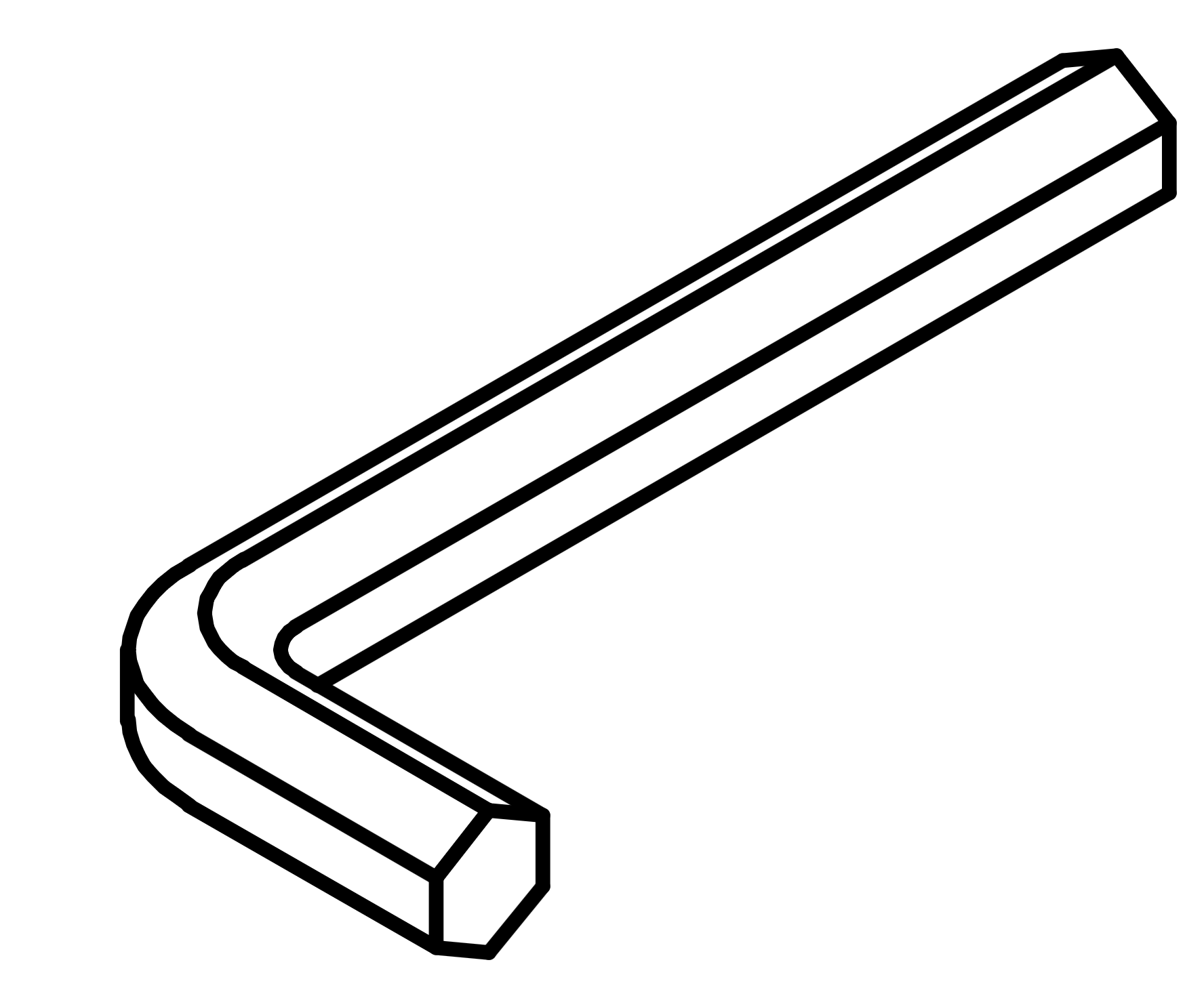
Insert three Bolts (H) into each side of the Metal Cross Rails (25, 26), connecting them to the Metal Leg Frames (24).
Use the Allen Key (M) to tighten the Bolts (H) securely, ensuring the frame is stable and aligned.
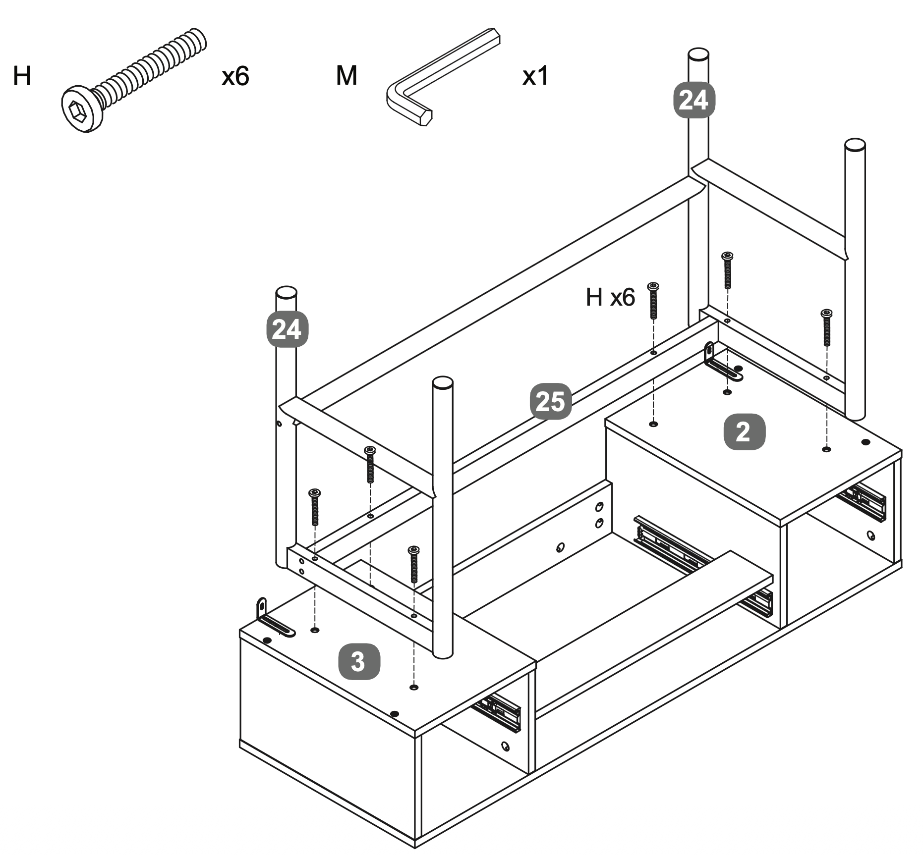
13. Cross Rail Alignment and Fastening
Position the Metal Cross Rail - Upper (25) between the two Metal Leg Frames (24).
Align the RH Base Panel (3) and LH Base Panel (2) with the Metal Leg Frames (24).
Insert six Bolts (H) through the pre-drilled holes in the Metal Cross Rail - Upper (25) and into the Metal Leg Frames (24).
Use the Allen Key (M) to securely tighten the Bolts (H), ensuring the assembly is stable and properly aligned.
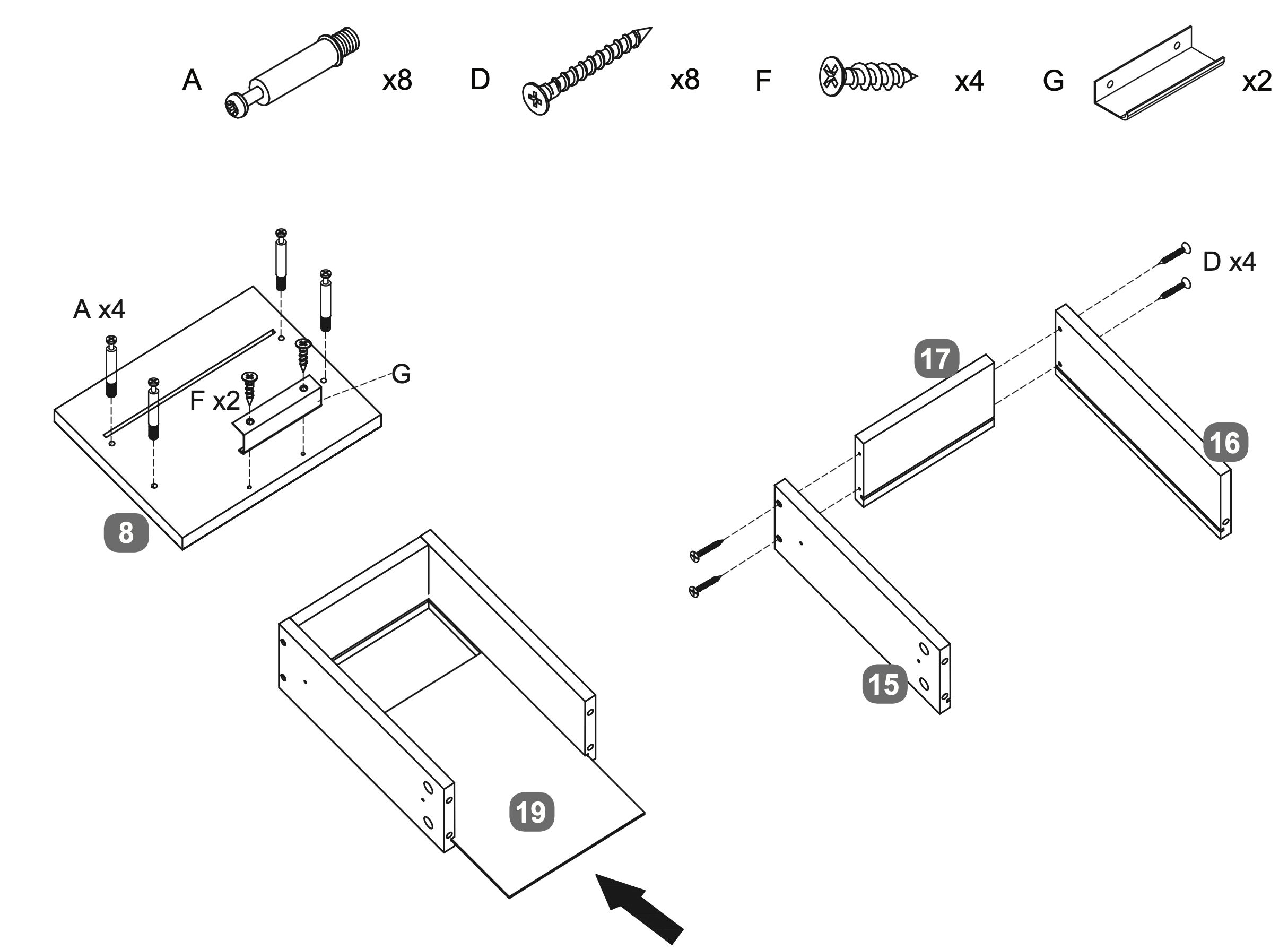
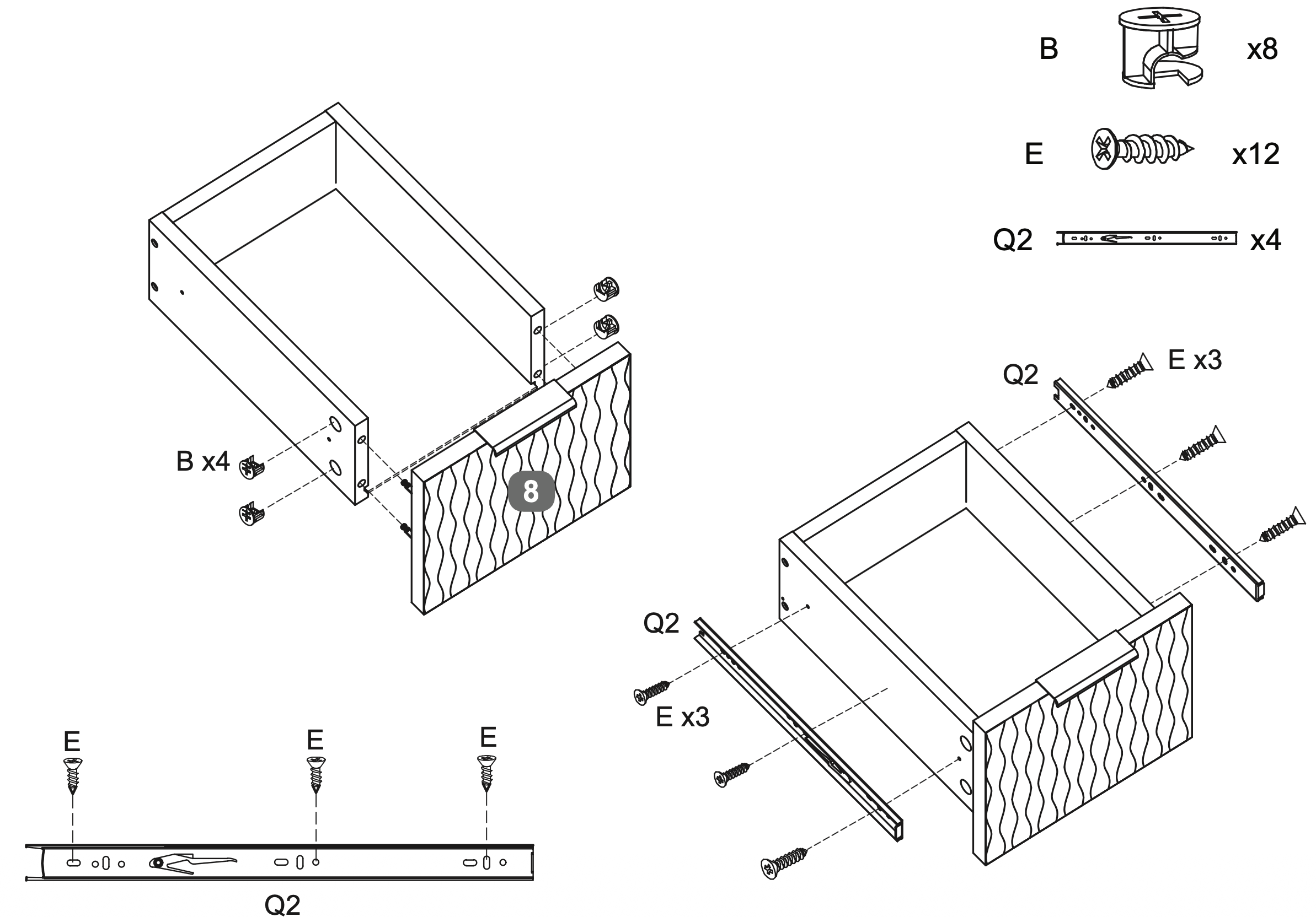
14. Drawer Frame Assembly and Attachment
Insert four Cam Dowels (A) into the designated holes on the Facia Panel - Side Drawer (8).
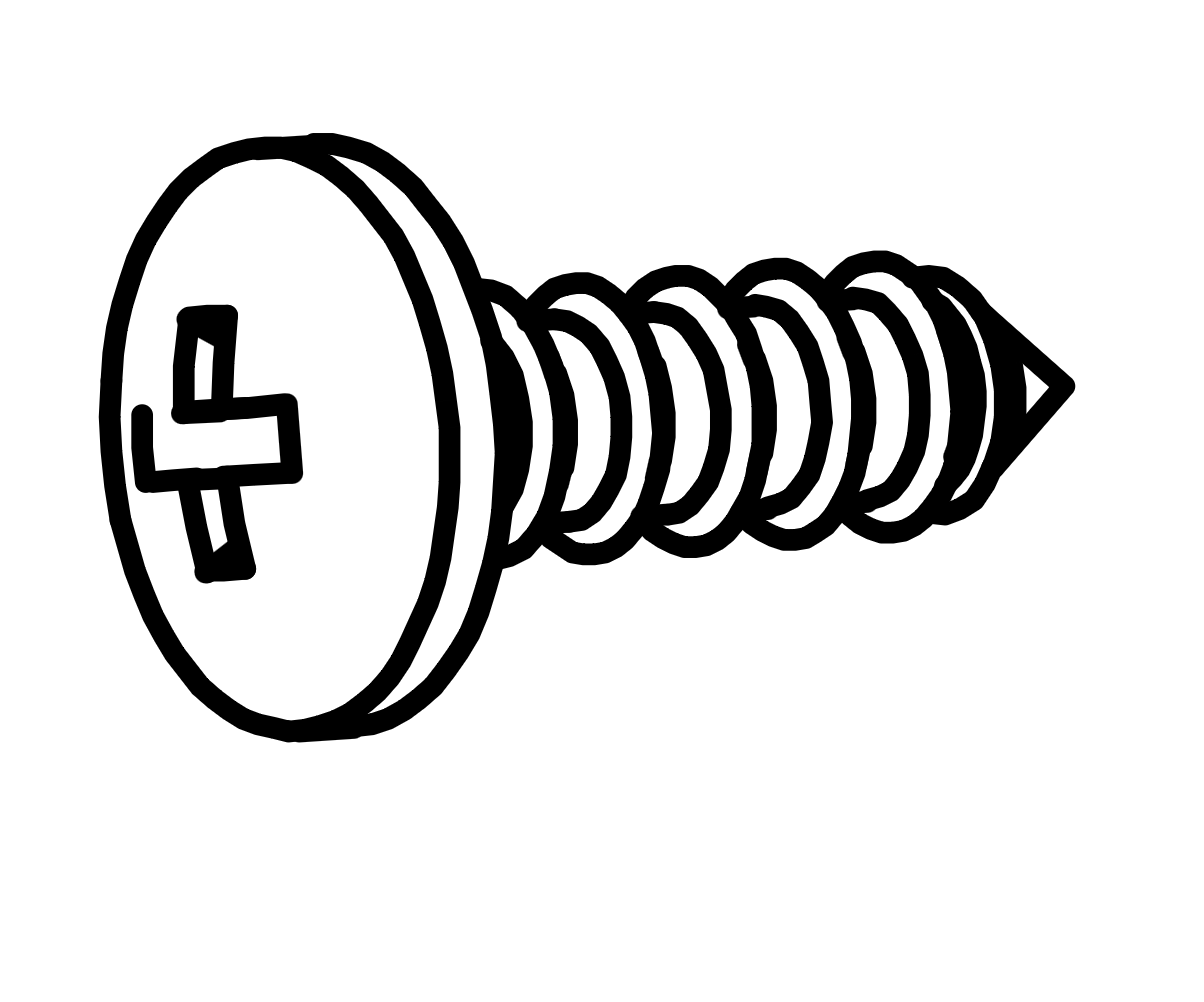
Attach the Handle (G) to the Facia Panel - Side Drawer (8) using two Screws (F).
Align the LH Side Panel - Side Drawer (15) and RH Side Panel - Side Drawer (16) with the DrawerBack Panel (17).
Secure the panels using four Screws (D).
Slide the Drawer Base Panel (19) into the grooves of the assembled drawer frame.
Repeat twice.
15. Drawer Assembly and Fastening
Insert four Cam Locks (B) into the designated holes on the LH and RH Side Panel - Side Drawers (15 and 16).
Secure the Facia Panel - Side Drawer (8) to the drawer frame by tightening the Cam Locks (B).
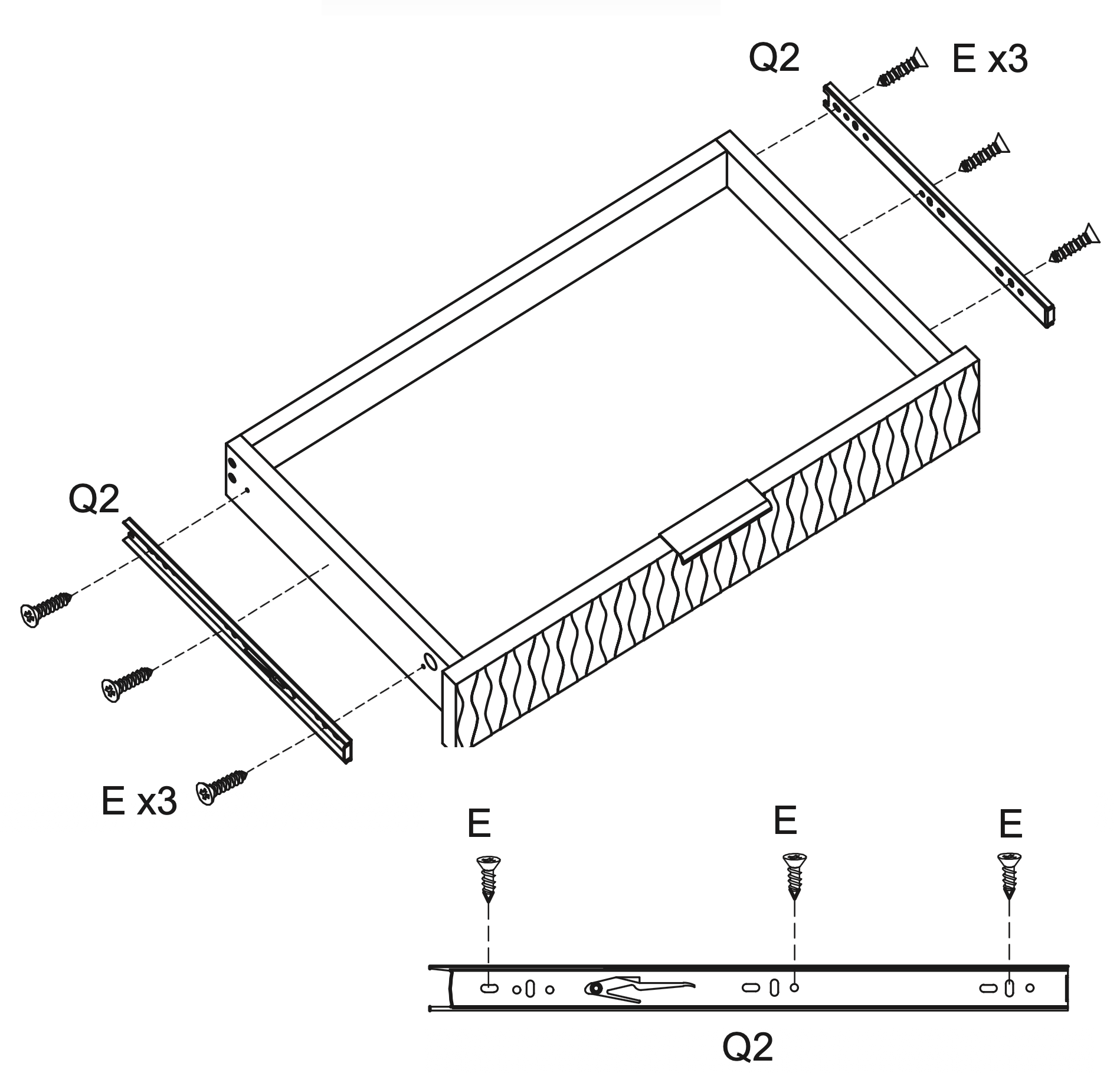
Attach two Runners (Q2) to each side of the drawer frame using three Screws (E) per runner, ensuring they are aligned and securely fastened.
Repeat twice.
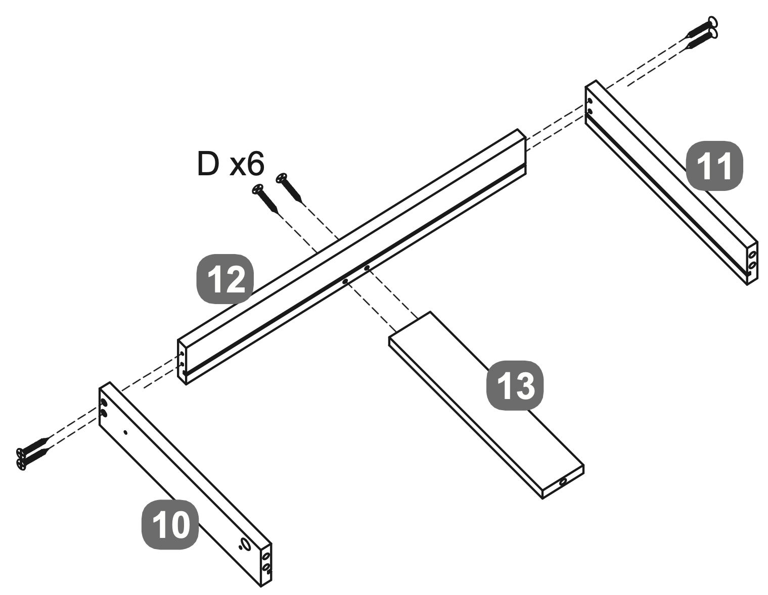
16. Frame Assembly and Panel Insertion
Align the LH Side Panel - Centre Drawer (10) and RH Side Panel - Centre Drawer (11) with the Back Panel - Centre Drawer (12). Secure them using two sets of Screw (D) on either side.
Slide the Base Support Rail - Centre Drawer (13) into the grooves of the assembled frame and use two more Screws (D) to secure this.
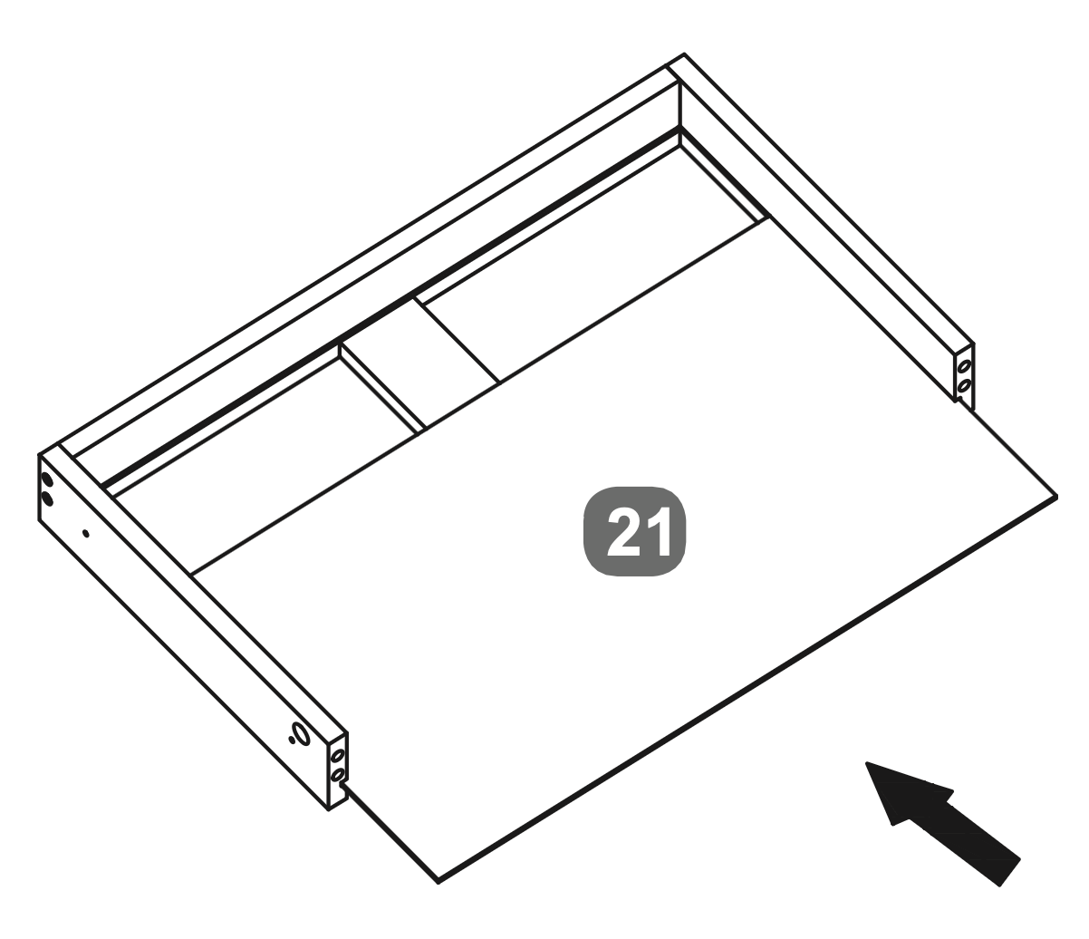
Insert the Back Panel (21) into the frame, ensuring it fits securely.
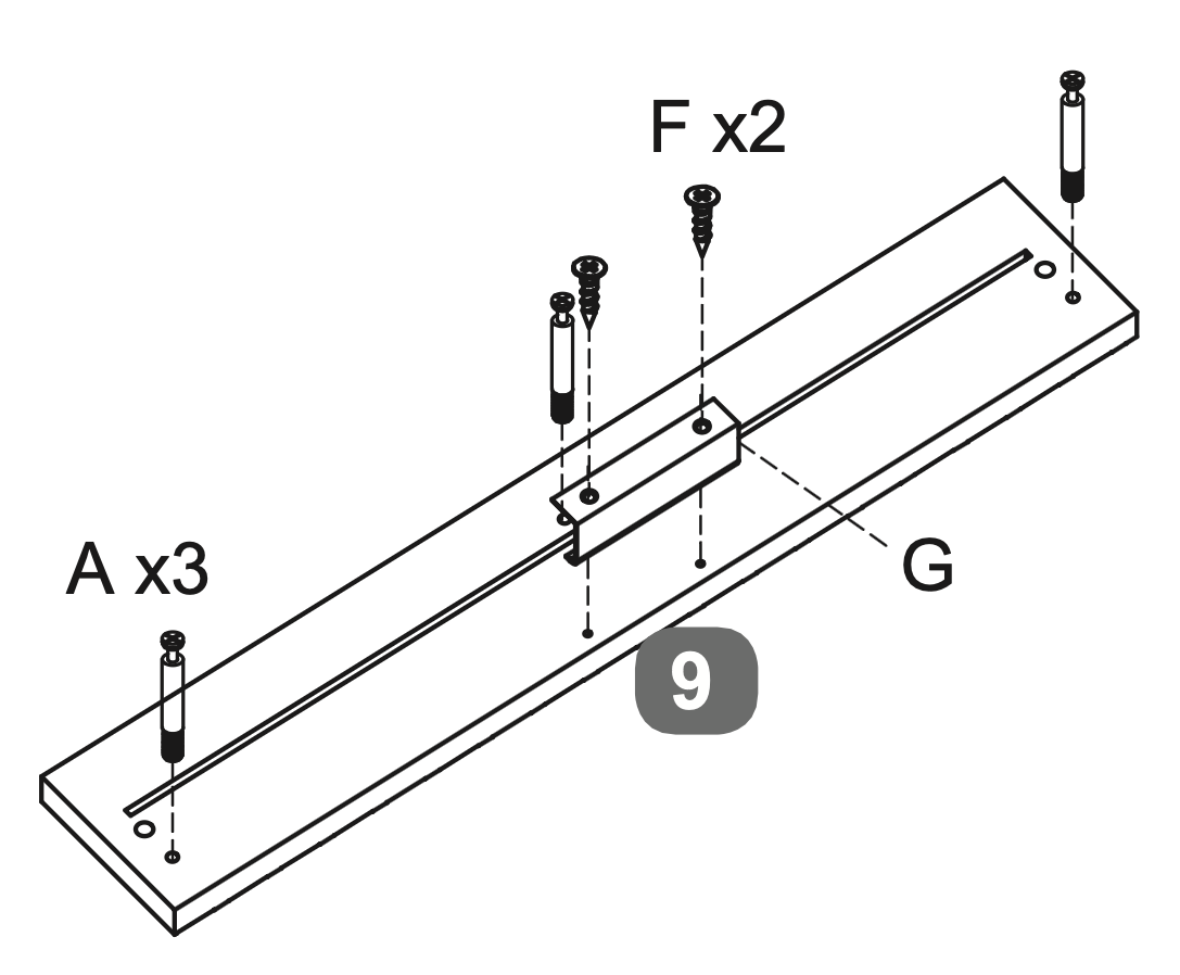
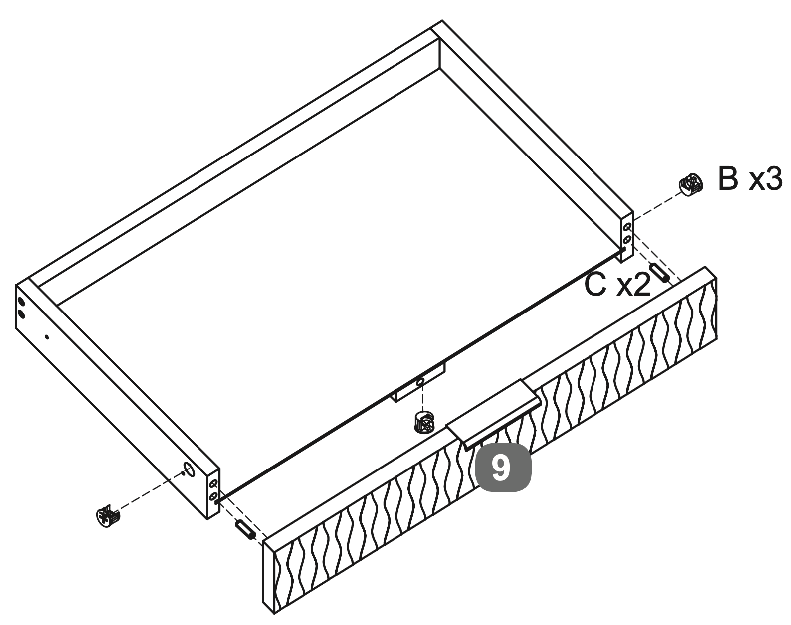
Insert three Cam Dowels (A) into the designated holes on the Facia Panel - Centre Drawer (9).
Attach the Handle (G) to the Facia Panel - Centre Drawer (9) using two Screws (F).
17. Drawer Frame Assembly and Fastening
Insert three Cam Locks (B) into the designated holes on the Side Panels (10 and 11).
Insert two Dowels (C) into the side panels of the drawer frame.
Secure the Facia Panel - Centre Drawer (9) to the drawer frame by tightening the Cam Locks (B).
Attach two Runners (Q2) to each side of the drawer frame using three Screws (E) per runner, ensuring they are aligned and securely fastened.
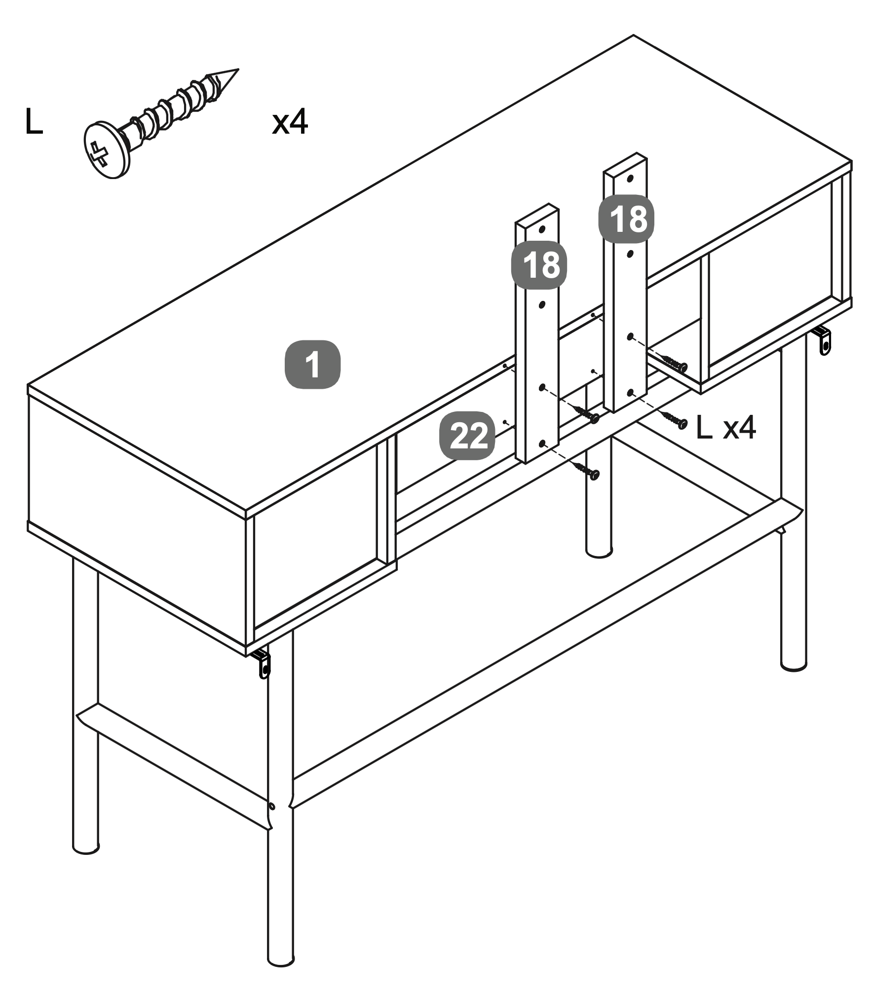
18. Support Rail Attachment and Alignment
\\Warning!\\Please use the correct screw: (L) is 28mm long with a round head
Attach the Mirror Support Rails (18) to the Top Panel (1) and Rear Cross Rail (22) using four Screws (L).
Ensure the Mirror Support Rails (18) are aligned with the pre-drilled holes on the Top Panel and Rear Cross Rail.
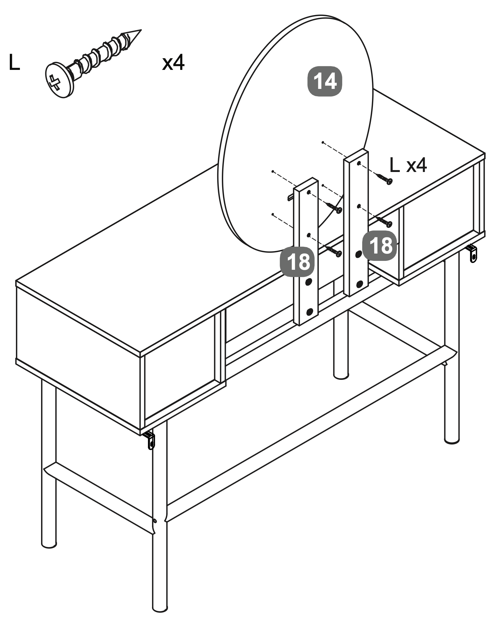
19. Mirror Attachment and Alignment
Warning! Please use the correct screw: (L) is 28mm long with a round head.
Attach the Oval LED Mirror (14) to the Mirror Support Rails (18) using four Screws (L).
Ensure the mirror is aligned with the uprights and securely fastened.
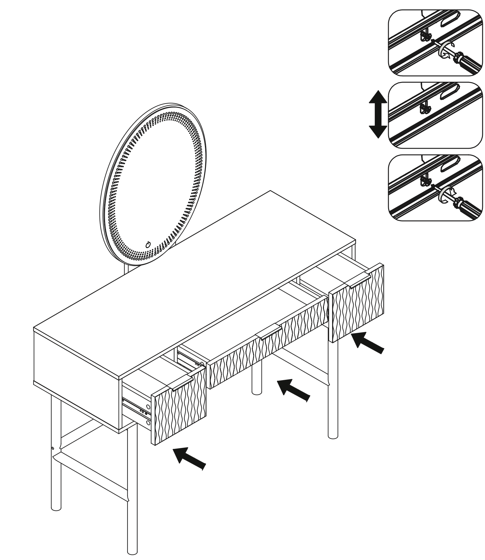
20. Drawer Installation and Alignment
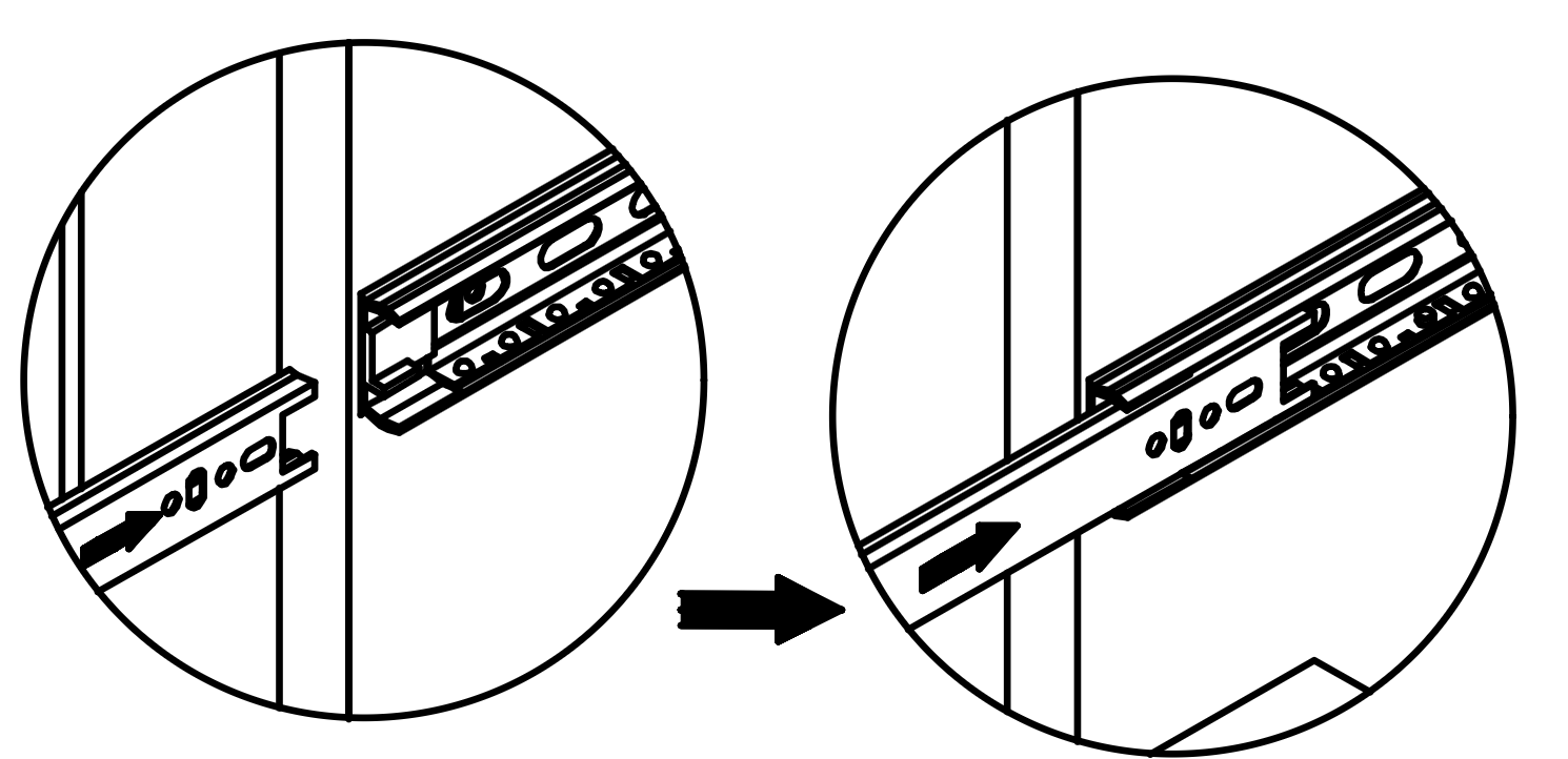
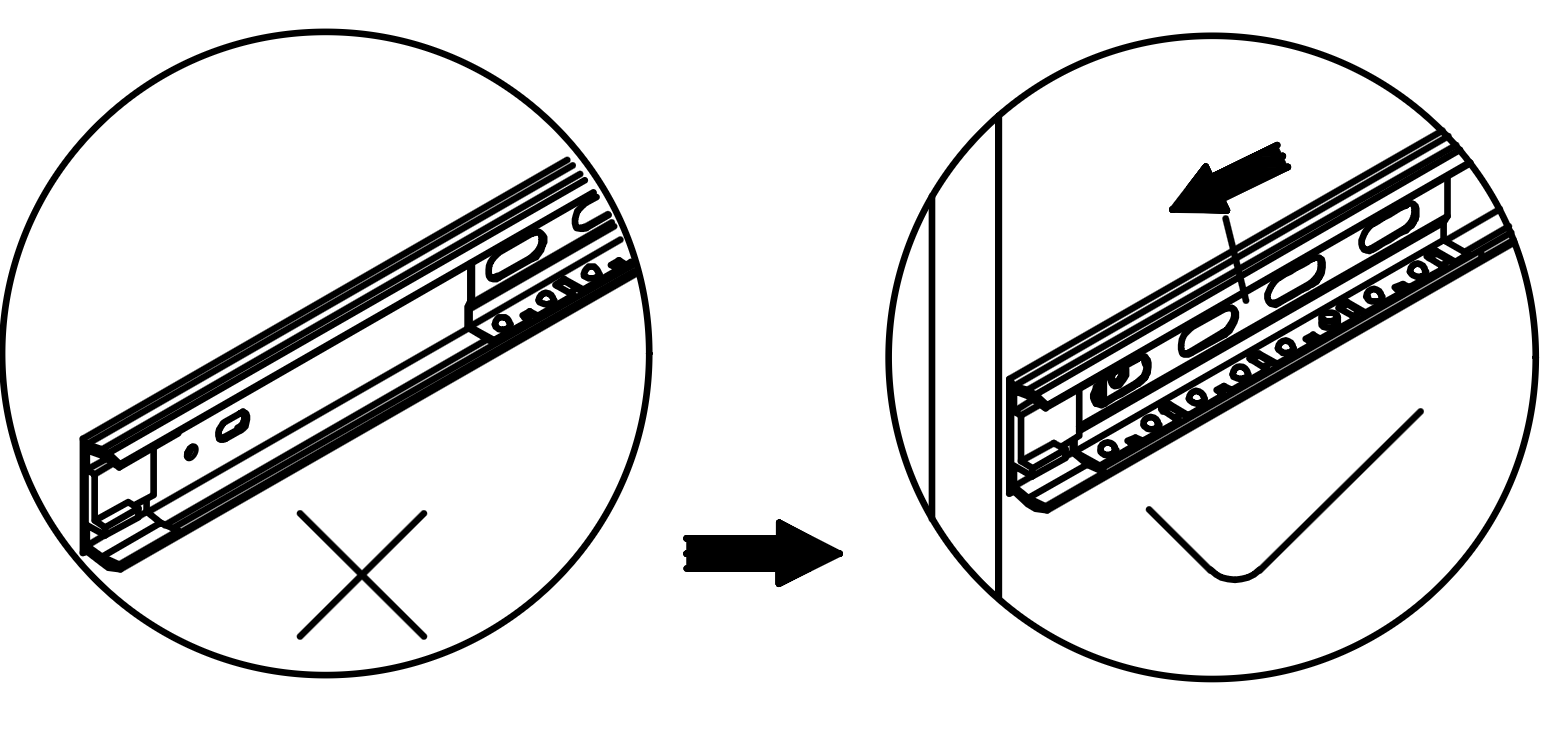
Insert each drawer into the corresponding compartment of the dressing table by aligning the Runners (Q2) on the drawer with the runners inside the compartment.
Ensure the runners are properly engaged by sliding the drawer in and out to check for smooth operation.
Adjust the runners if necessary to ensure they are correctly aligned and securely fastened.
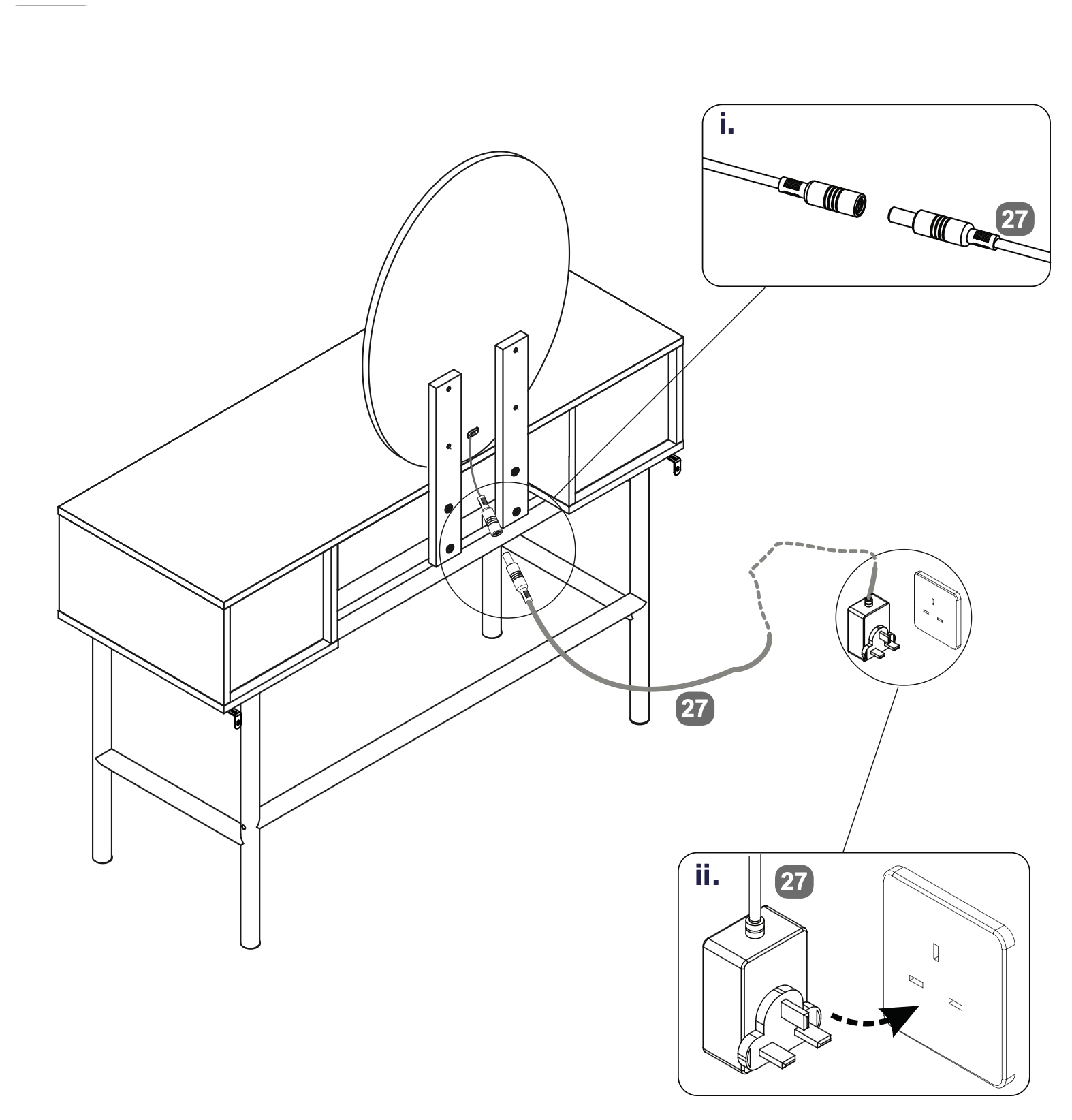
21. Power Connection Setup
Connect the Power Supply Adapter (27) to the socket on the back of the Oval LED Mirror (14) by aligning and inserting the connectors as shown in the detail view (i).
Plug the other end of the Power Supply Adapter (27) into a wall outlet to power the LED mirror, as illustrated in detail view (ii). Ensure the connection is secure and the adapter is properly inserted into the outlet.
22.
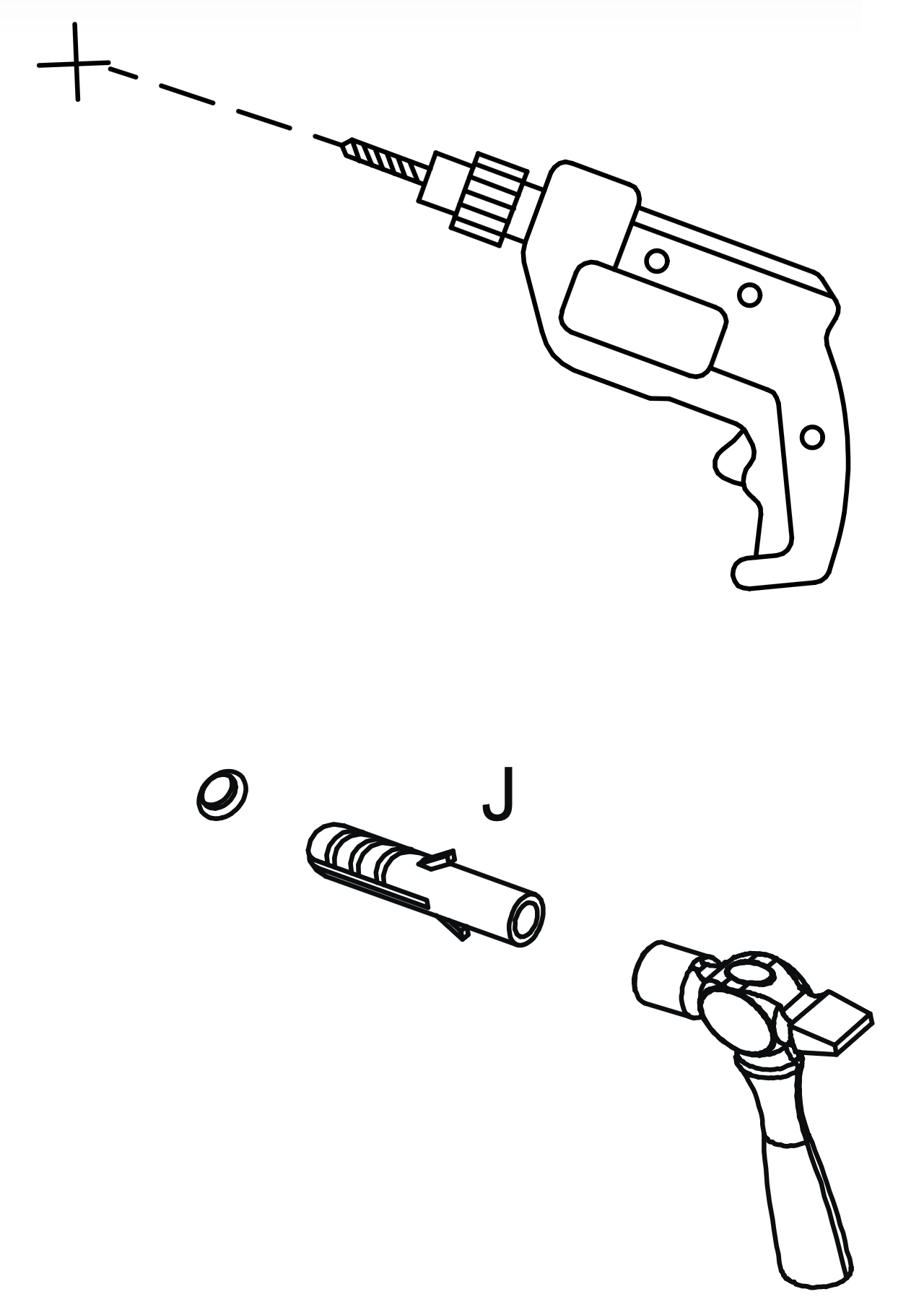
Warning: Always ensure the area to be drilled is free from hidden electrical wires, water and gas pipes.
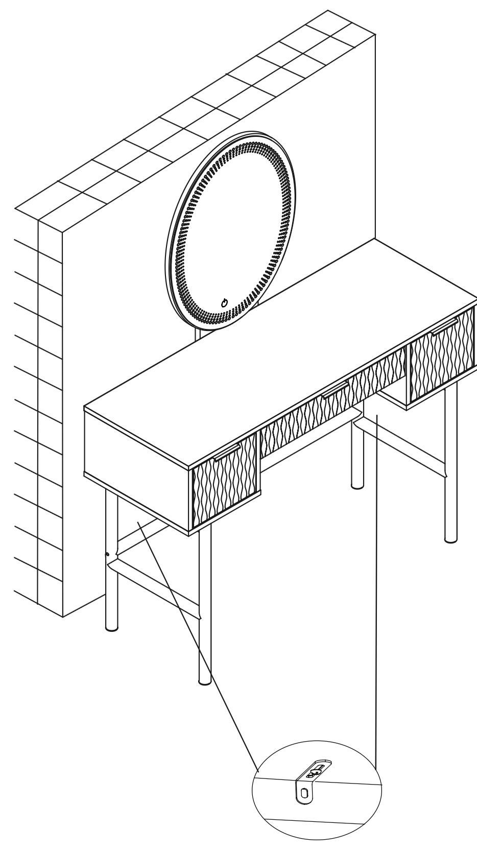
Place the table in the position in which it will be used, flat against a wall. (I)
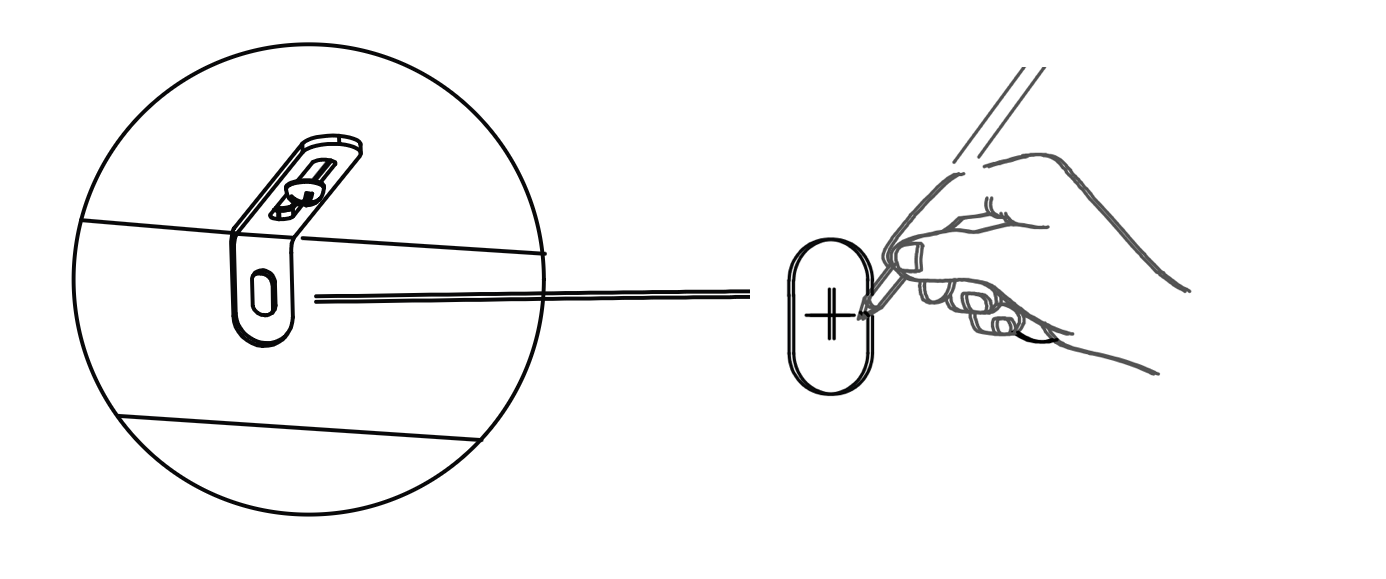
From the underside of the base panel (2) carefully mark the wall with a sharp pencil, dead-centre of the holes in the short leg of the Metal Anti-tilt Bracket.
Carefully drill holes through the marks into the wall.
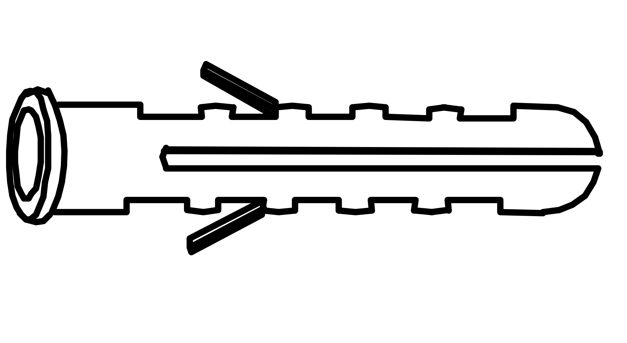
If the wall is suitable, tap in the wall plug provided. If it isn't, use an appropriate fixing.
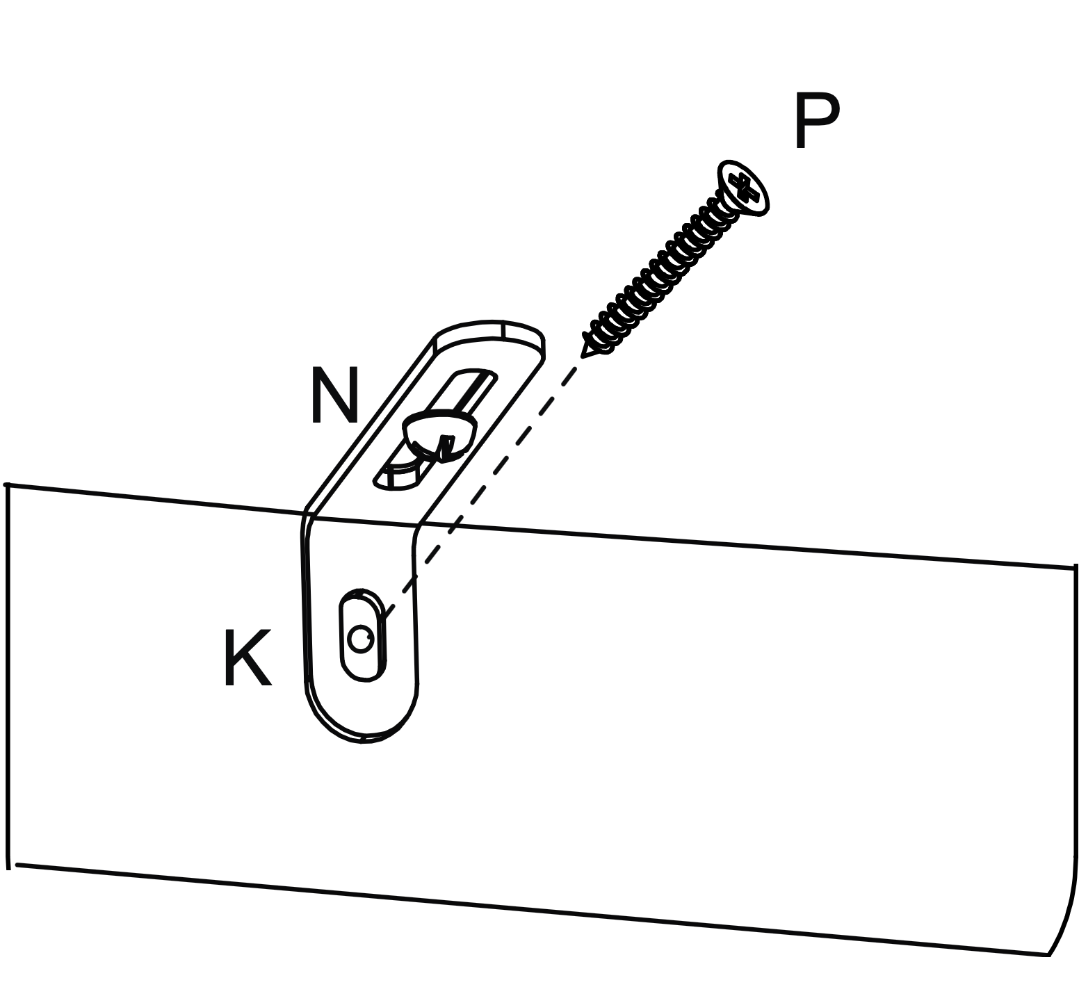
Hold the table firmly against the wall. If necessary loosen screw (N) a little and push the short leg of the metal bracket (K) firmly against the wall. Screw into the wall fixings making sure brackets are firm, finally retighten screws (N).