Assembly instructions for Molle Ottoman Storage Bed Frame by Time4Sleep
Product Information
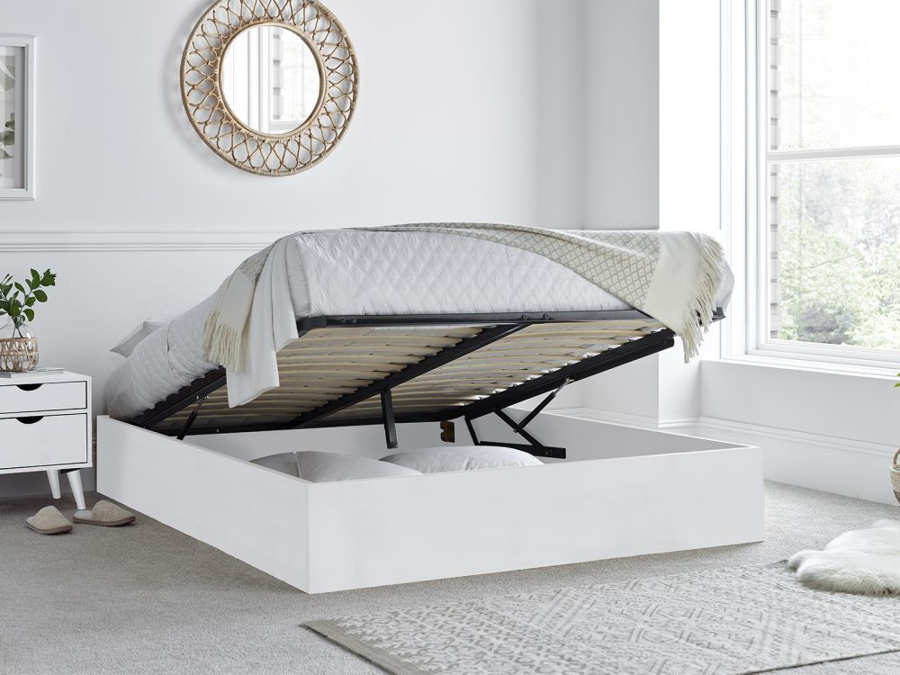
Molle Ottoman Storage Bed Frame
Introducing our Molle White Ottoman bed base, a versatile and stylish addition to your bedroom that combines functionality and contemporary looks. This bed base offers a sturdy construction, a sprung slatted base, and a fabric-lined floor.
The ottoman design allows you to maximize your bedroom space effectively and provides approximately 4 times more storage than a traditional drawer bed. Lift the top of the bed base to reveal a spacious storage area underneath, providing ample room to store occasional use items. Say goodbye to clutter and create a neat and organized environment in your bedroom.
Designed for comfort and support, the sprung slatted base of this bed base offers excellent mattress support whilst the flexible slats also enhance ventilation and helps to promoting air circulation to keep your mattress fresh and hygienic. To enhance durability and protect your belongings, the floor of the ottoman storage area is lined with fabric. This lining adds an extra layer of protection and prevents your stored items from coming into contact with the floor.
Please note this listing is for the ottoman base only. Should you require a headboard with this product please refer to the listing Molle Ottoman including headboard.
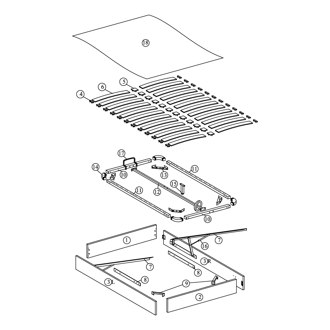
6Slats - 24 slats (645 mm) for Double, 28 slats (745 mm) for King.
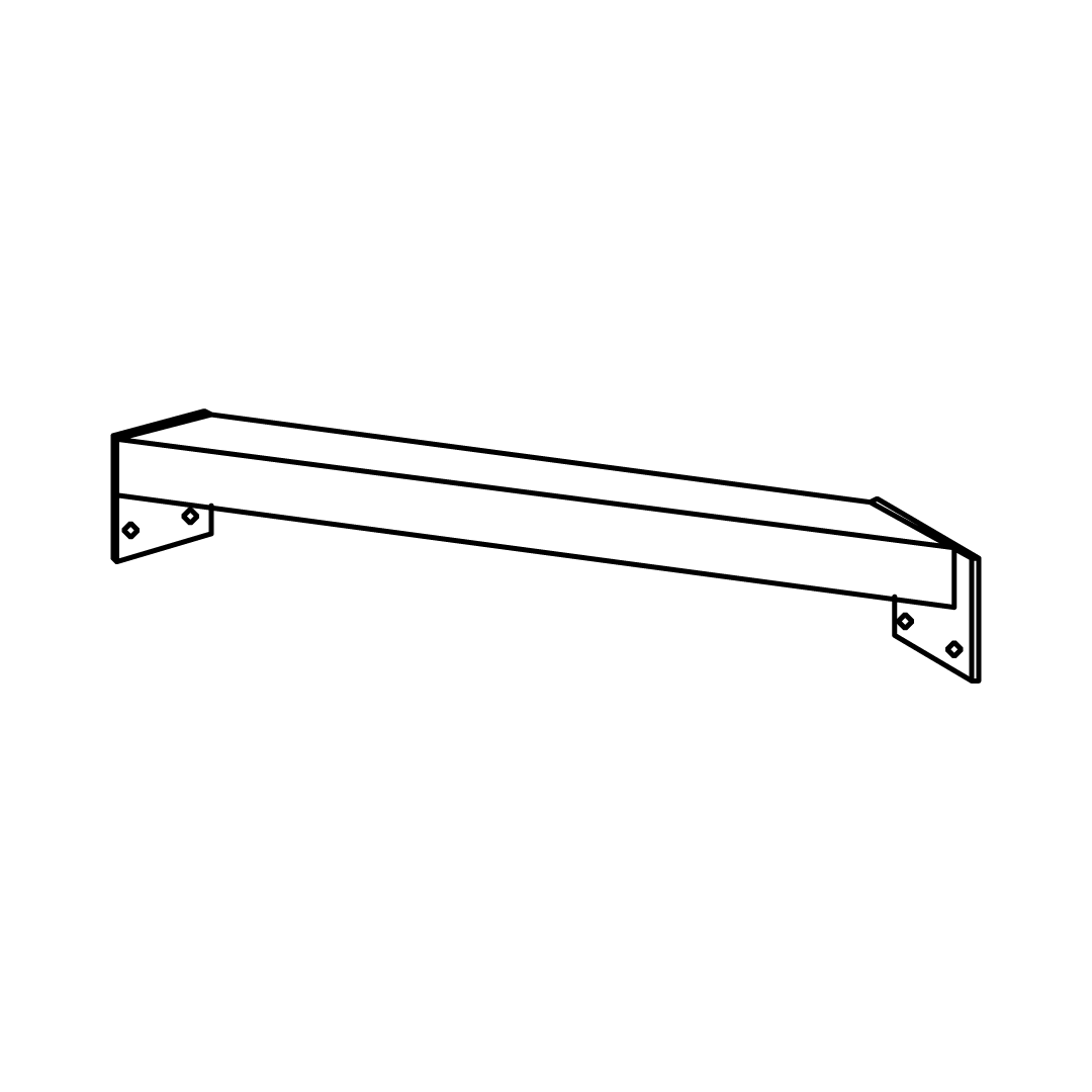
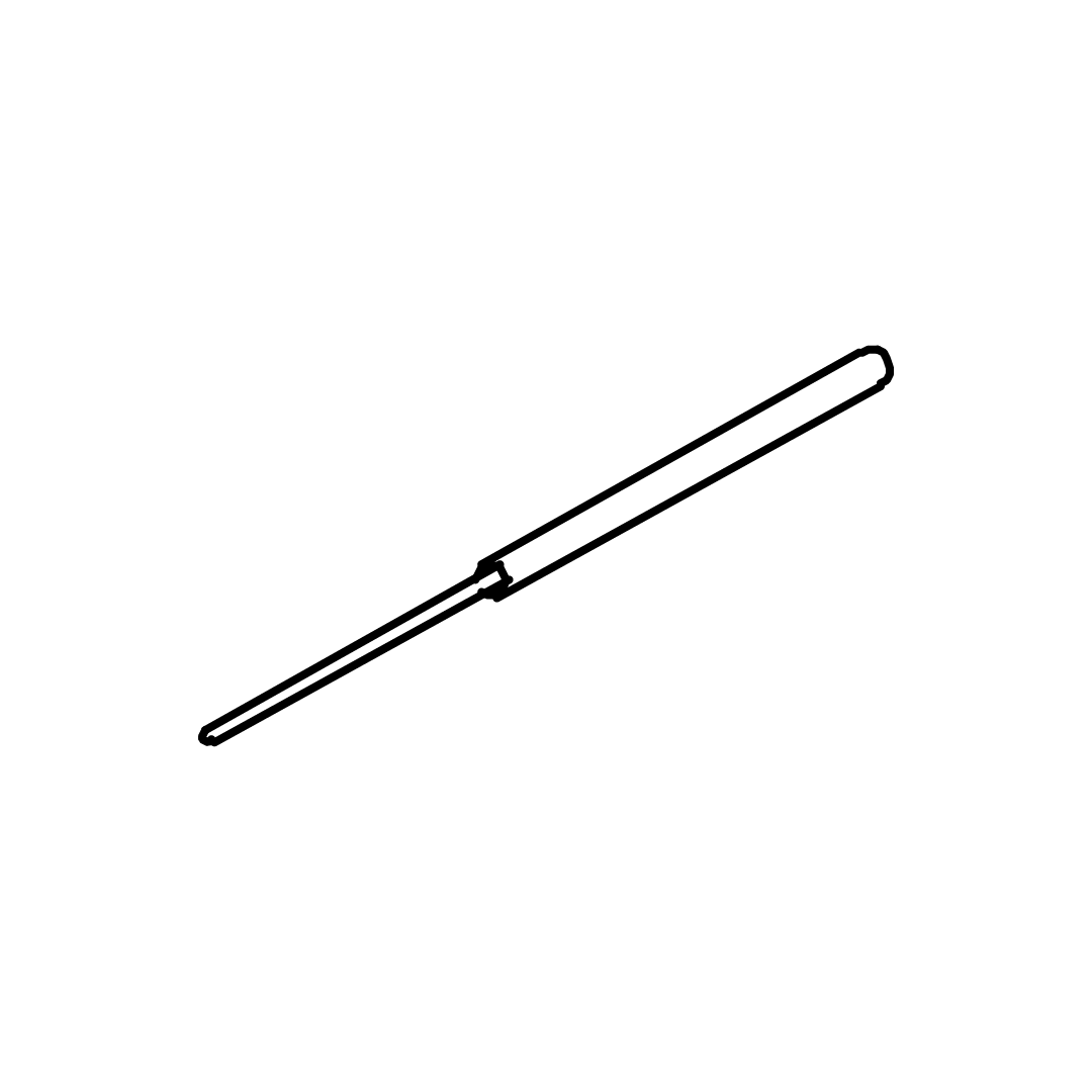
7Pump Mounting Bracket
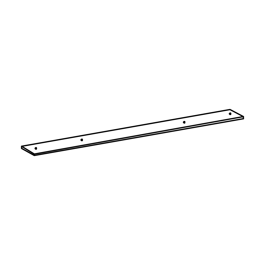
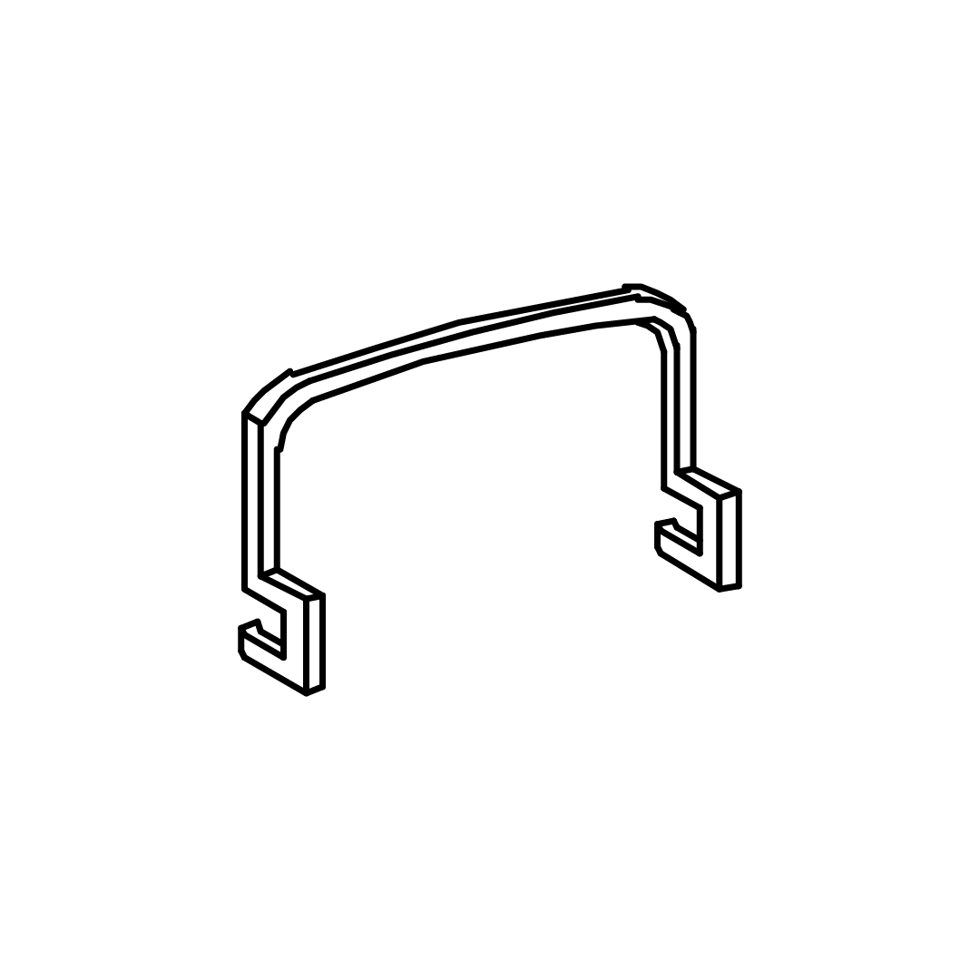
8Bracket Base
9FB / SR Angle Bracket
10 Main Frame (Front & End)
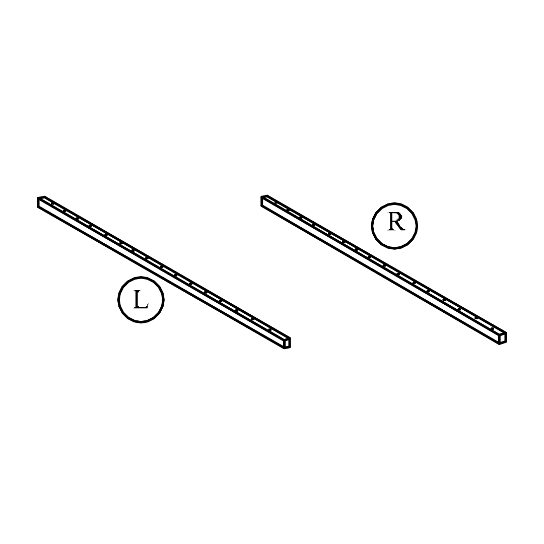
11Main Frame (Side)
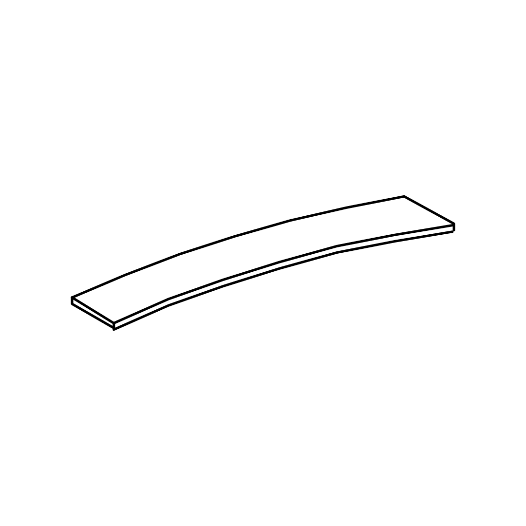
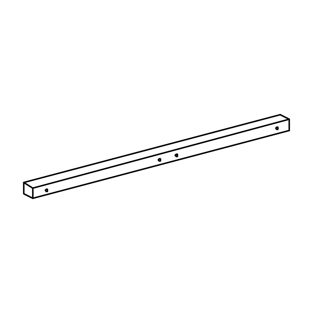
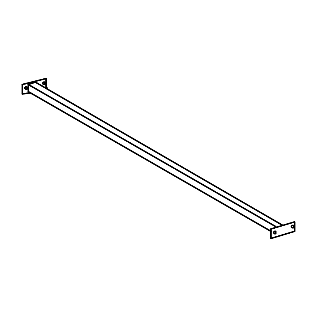
12Center Rail
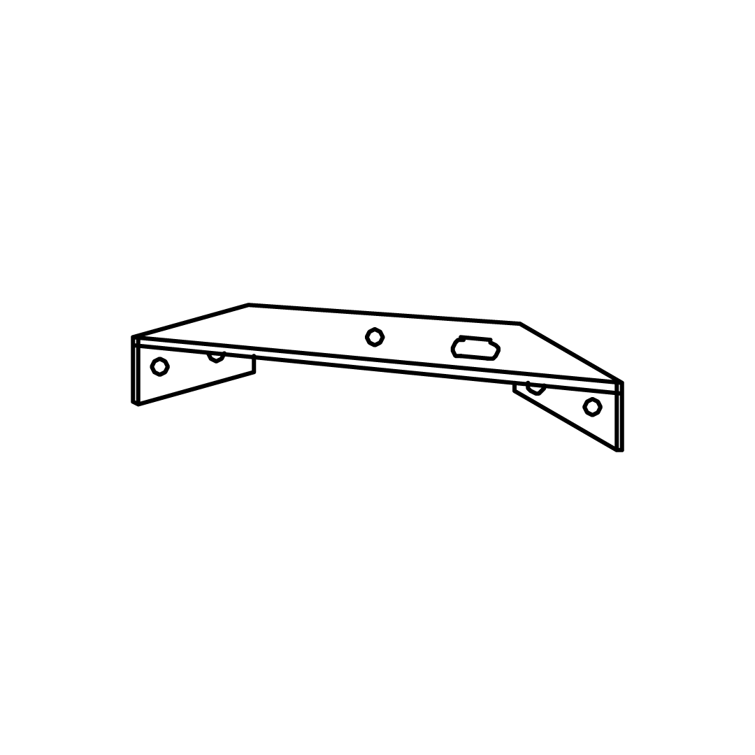
13Metal Corner Bracket
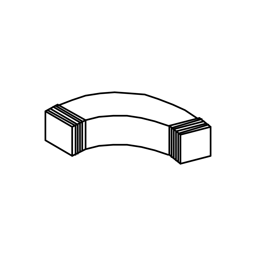
14Rubber Corner Connector
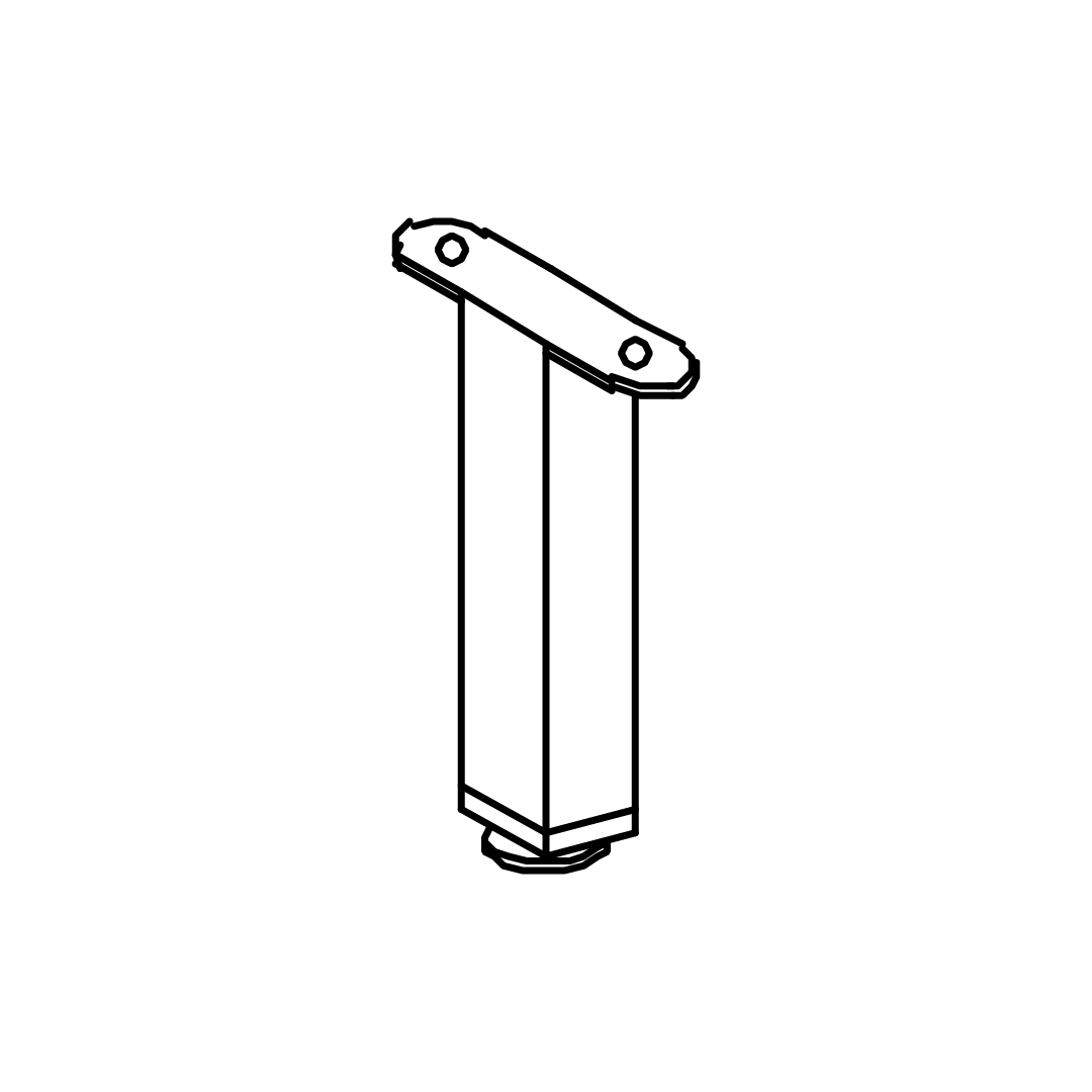
15Support Legs 215mm
16Gas Spring
17Stopper
18Black Woven
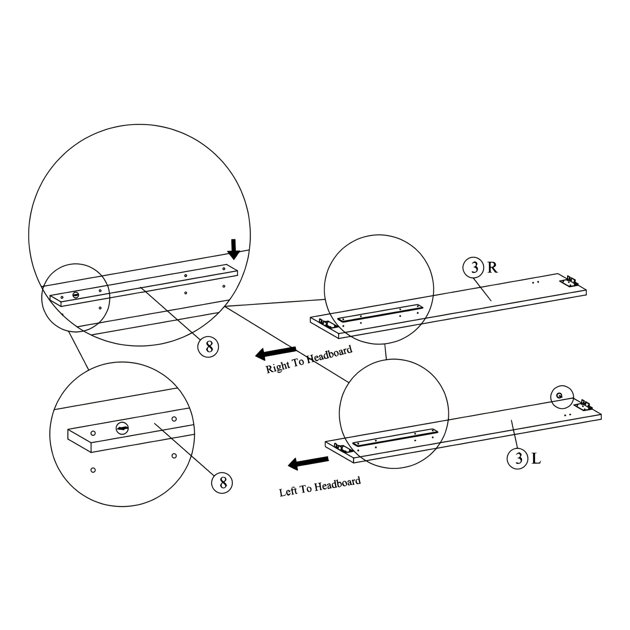
1. Attaching Bracket Bases
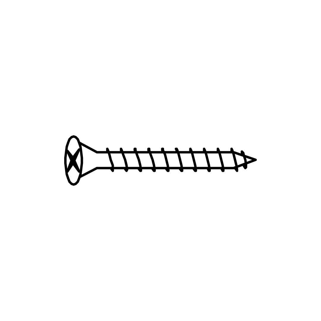
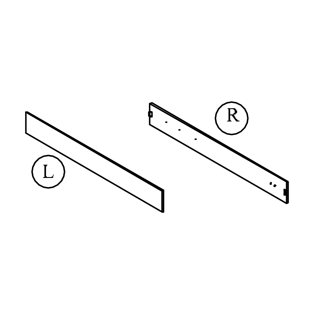
1. Position the Right (R) and Left (L) Side Rails with the correct orientation, as indicated. 2. Align the holes on the bracket base with the pre drilled holes and attach the Bracket Bases (8) with CSK M4x32 screws (S), secure them to the inner sides of each rail, place these screws evenly on the bracket bases to secure these but don't cover the pre drilled holes. Ensure the brackets face the correct direction towards the headboard.
Important: Part 8 (Bracket Base) must be attached before installing Part 7 (Pump Mounting Bracket) to ensure proper assembly.
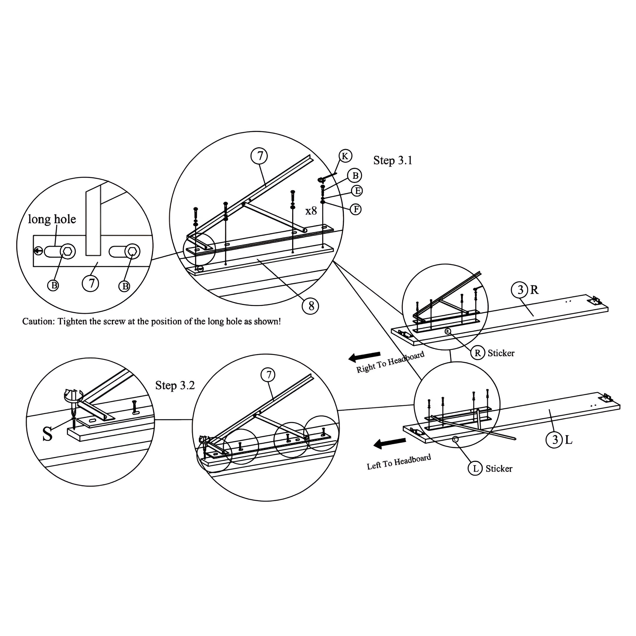
2. Installing Pump Mounting Brackets
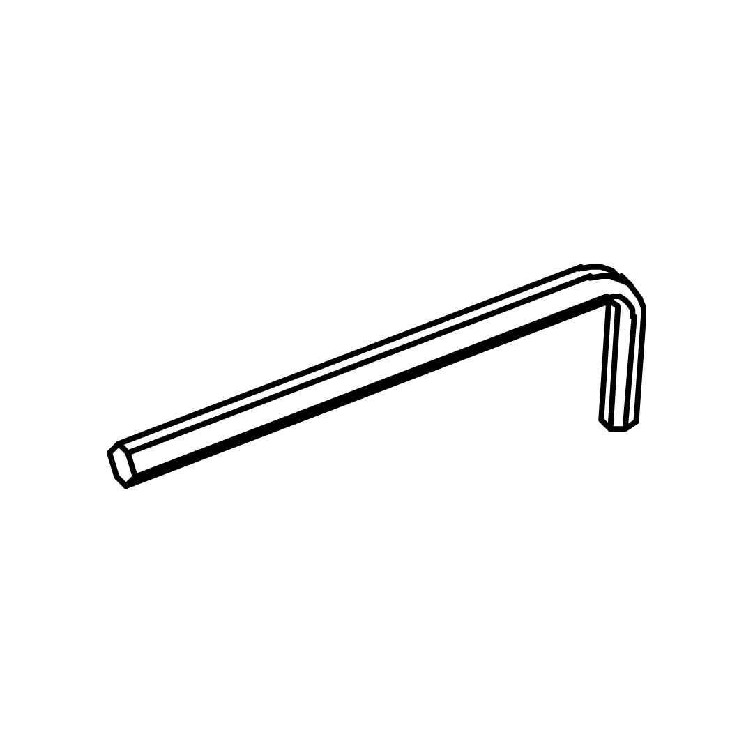
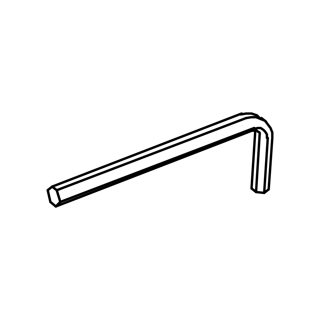
1. Attach Pump Mounting Brackets (7), position the brackets on the Right (R) and Left (L) Side Rails as shown. 2. Secure using JCBC M6 X 40 screws (B), M6 Spring Washers (E), and M6 Flat Washers (F) through the pre-drilled holes in Bracket Base (8). 3. Use the M4 Allen Key (K) to tighten the screws securely.
Caution: Tighten the screw at the position of the long hole as shown
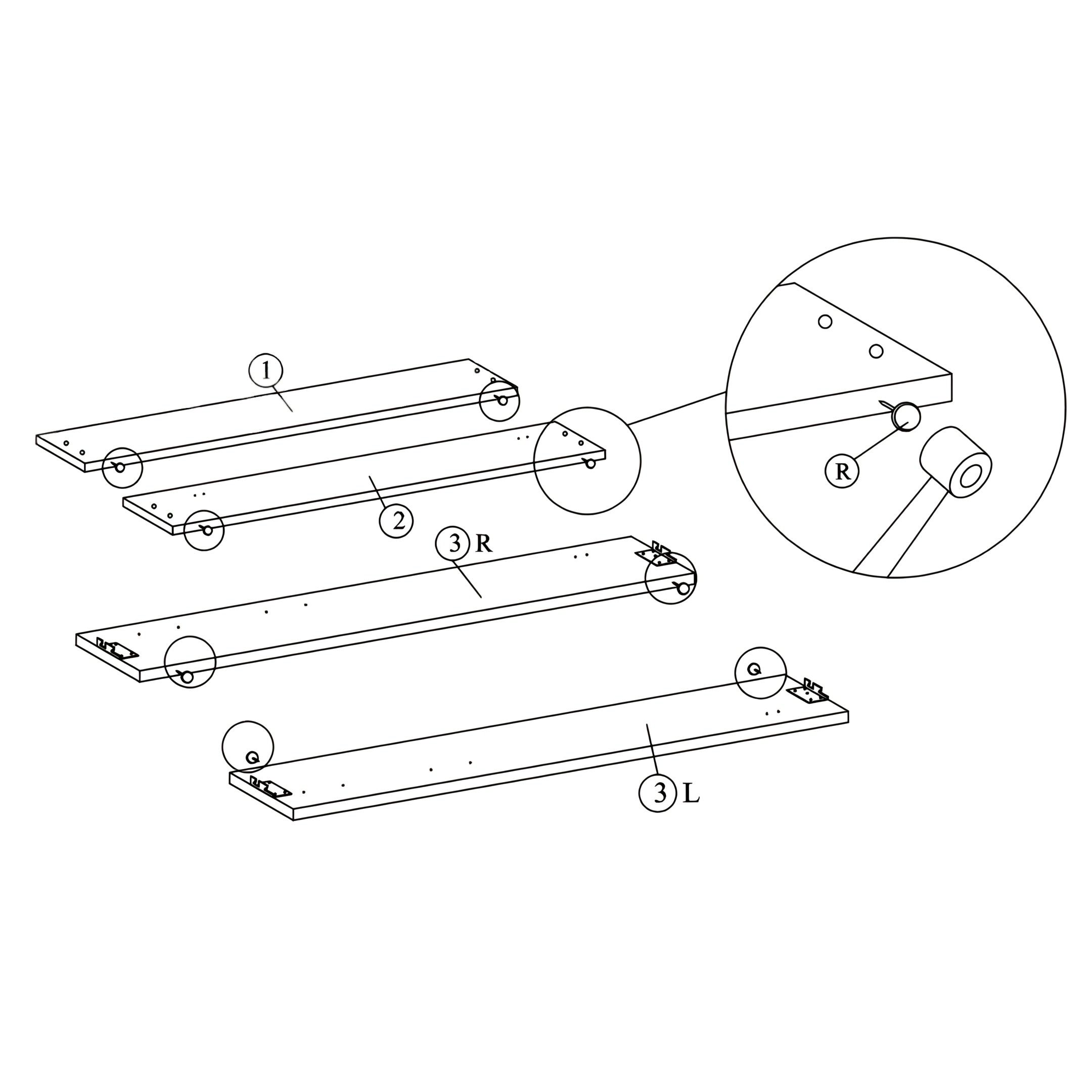
3. Attaching Nails
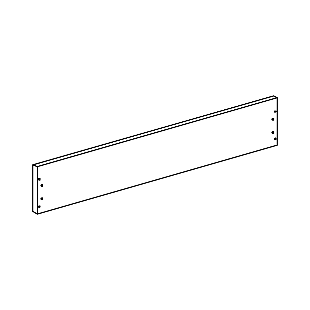
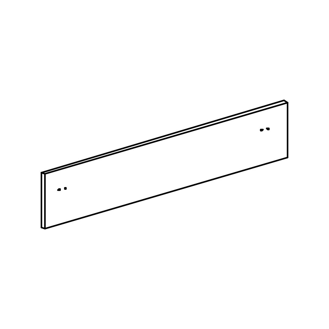
1. Lay out the Headboard (1), Footboard (2), and Side Rails (R & L). 2. Insert the white nails (R) on the unfinished side of all the parts, ensuring they are not too close to the edges. 3. Verify the nails are secured and correctly positioned as shown in the detail view.
Tip: Position nails centrally to avoid weakening the edges
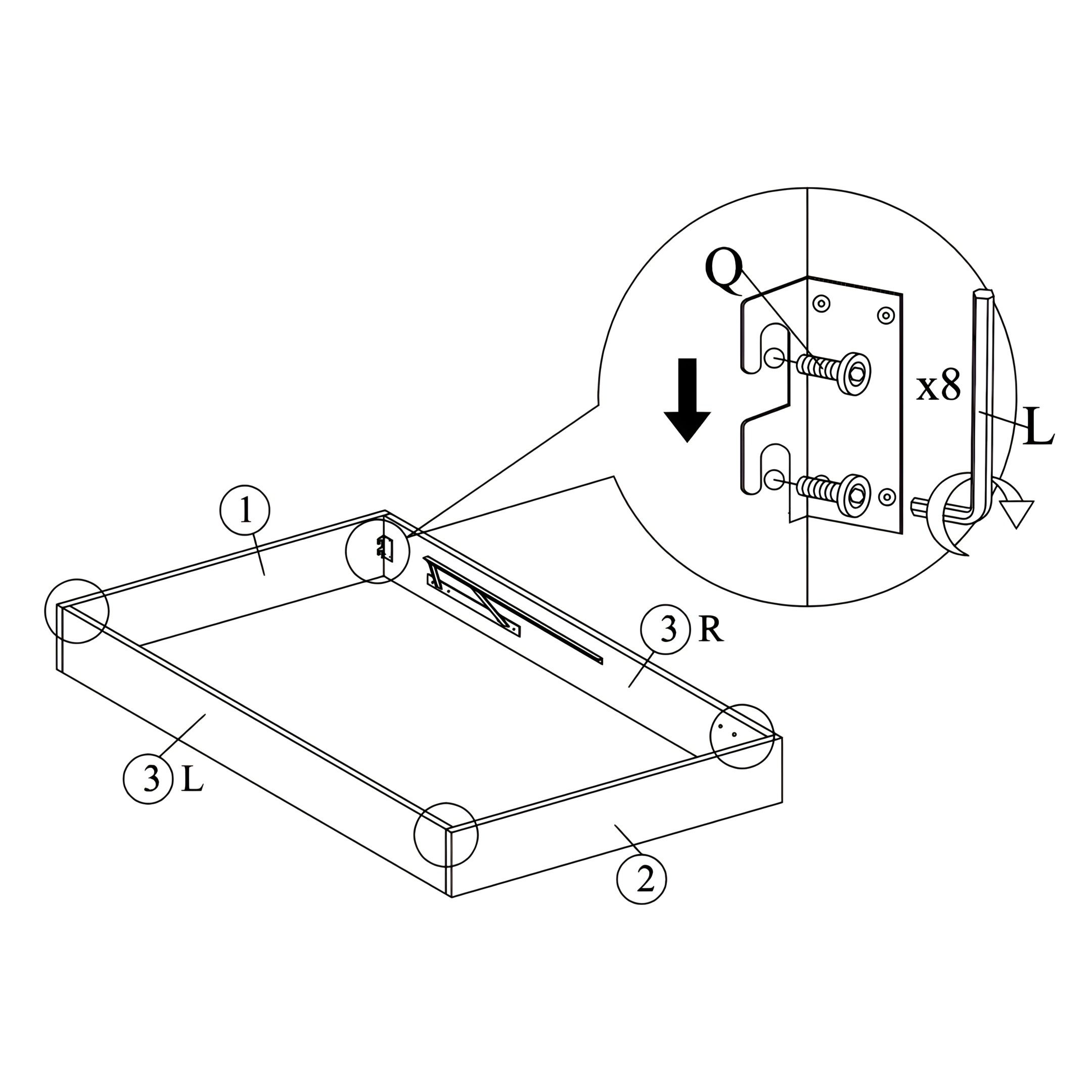
4. Assembling the Bed Frame
1. Arrange the Headboard (1), Footboard (2), and Side Rails (R & L) to form the bed frame. 2. Secure the Angle Brackets using the provided JCBC M6 X 40 screws (Q). 3. Tighten the screws using the M5 Allen Key (L) to ensure a firm connection.
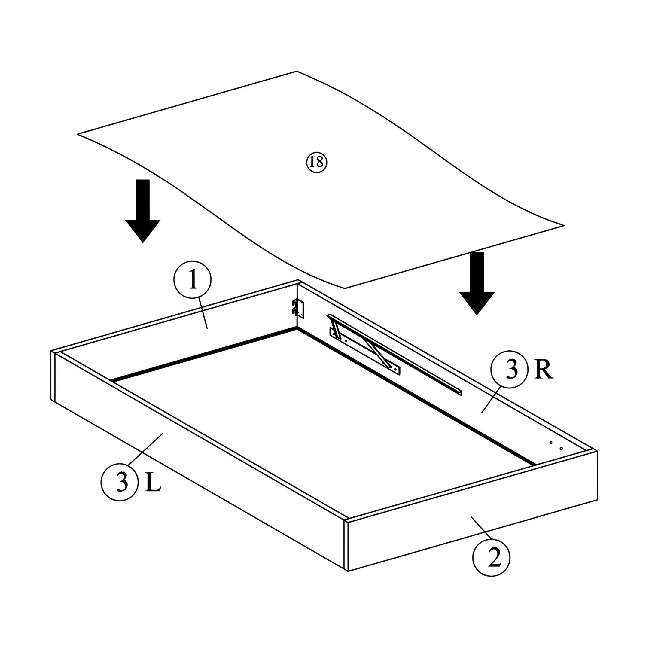
5. Placing the Black Woven Base
1. Place the Black Woven (18) on top of the bed frame, ensuring it aligns with the edges. 2. Attach the woven base to the frame using the Velcro strips provided, ensuring a firm and even fit.
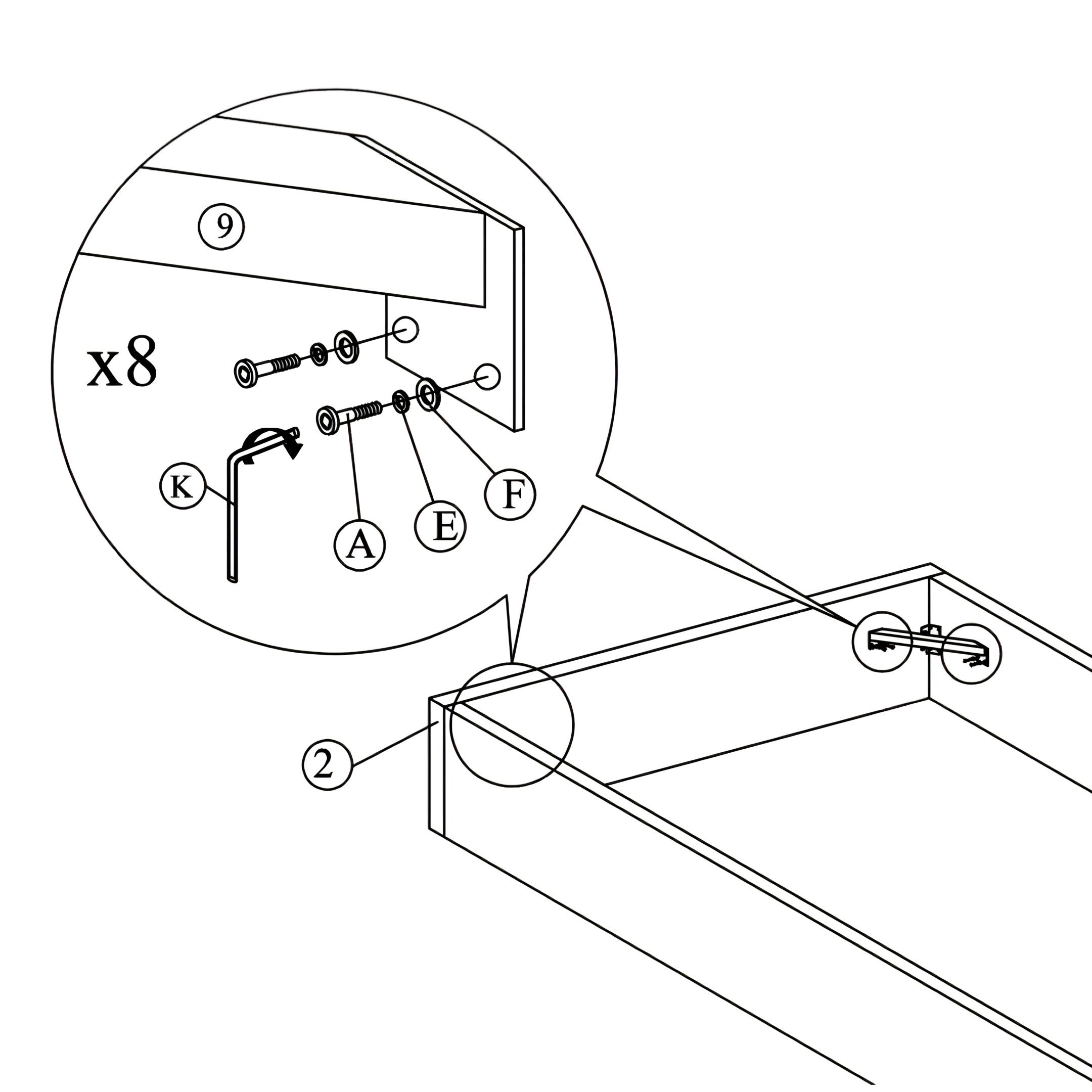
6. Attaching the Angle Brackets
1. Align the brackets at the designated locations inside the frame, as shown in the illustration. 2. Use JCBC M6 X 20 screws (A), M6 Spring Washers (E), and M6 Flat Washers (F) to attach the brackets. 3. Tighten the screws using the M4 Allen Key (K) for a secure fit.
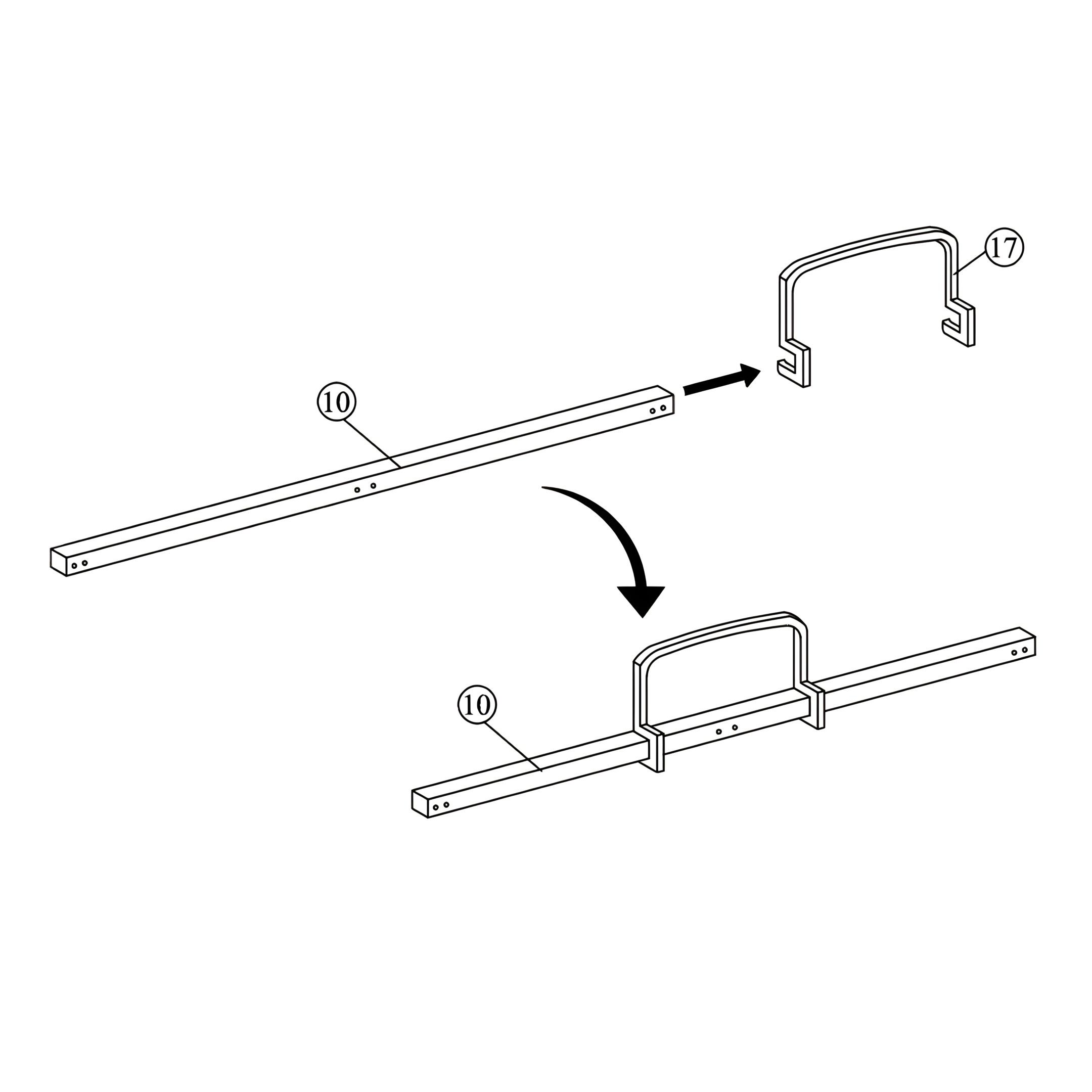
7. Attaching the Stopper
1. Align the stopper with the designated slot on the Main Frame (10). 2. Slide it securely into place, ensuring it fits firmly onto the frame and does not move freely.
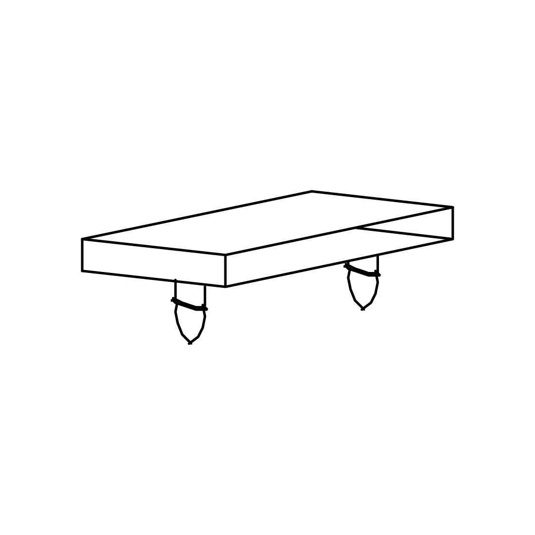
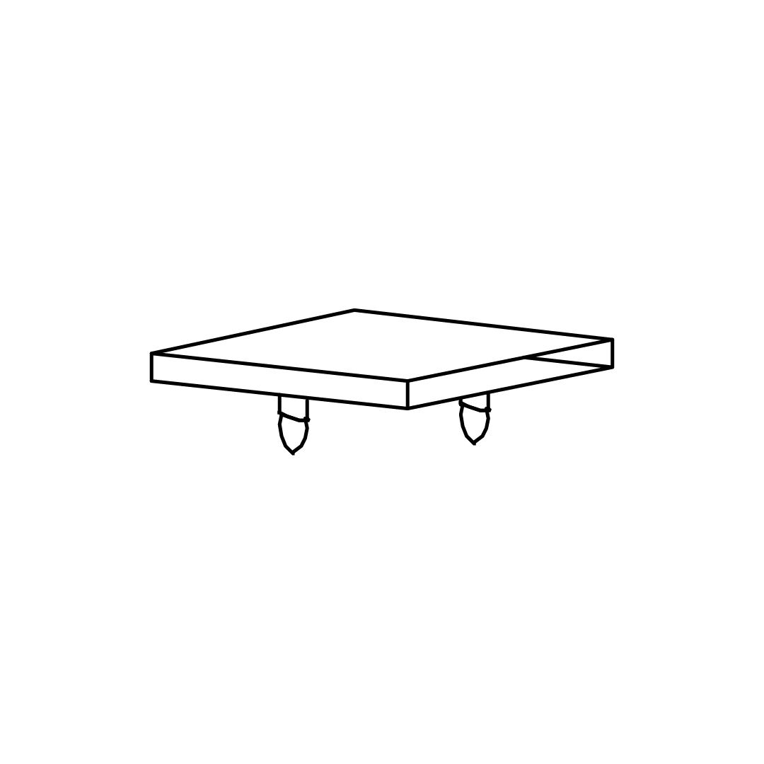
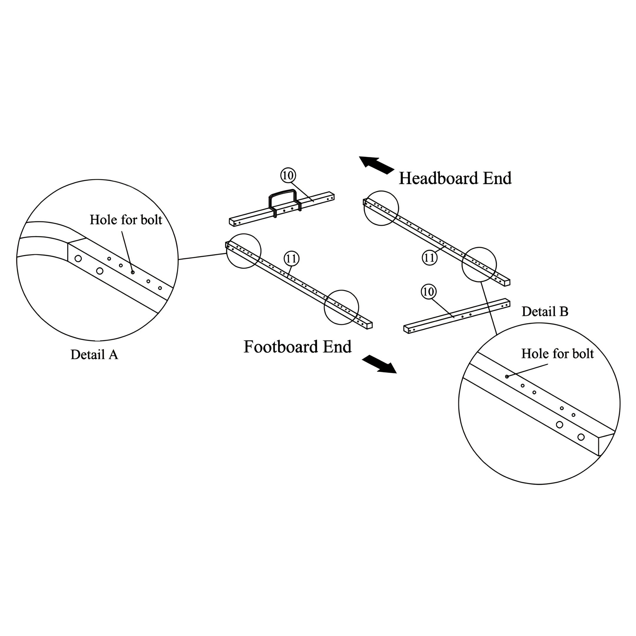
8. Positioning the Main Frame Supports
1. Position the Main Frame - Front and End (10) and Side Frames (11) at the headboard and footboard ends. 2. Fix the hole for the bolt between the first and second pair of holder holes to the headboard end. 3. Fix the hole for the bolt between the second and third pair of holder holes to the footboard end.
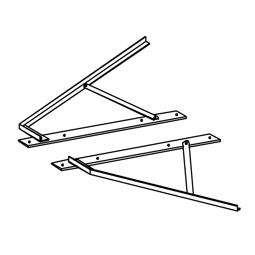
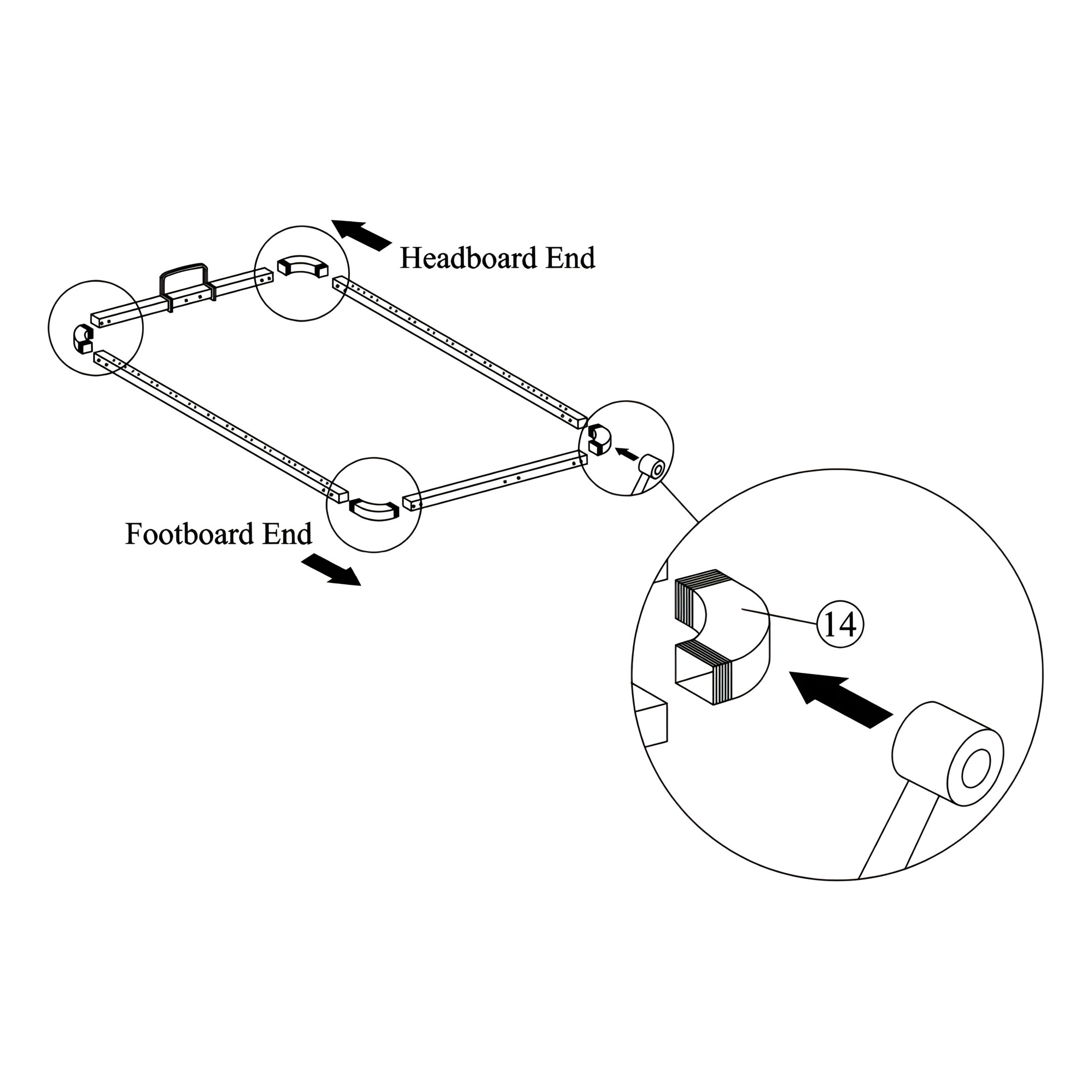
9. Securing the Frame with Rubber Corner Connectors
1. Attach the Rubber Corner Connectors (14), position the connectors at each corner where the Main Frames (10) and Side Frames (11) meet. 2. Firmly press the rubber connectors into place, ensuring they lock the frame sections together.
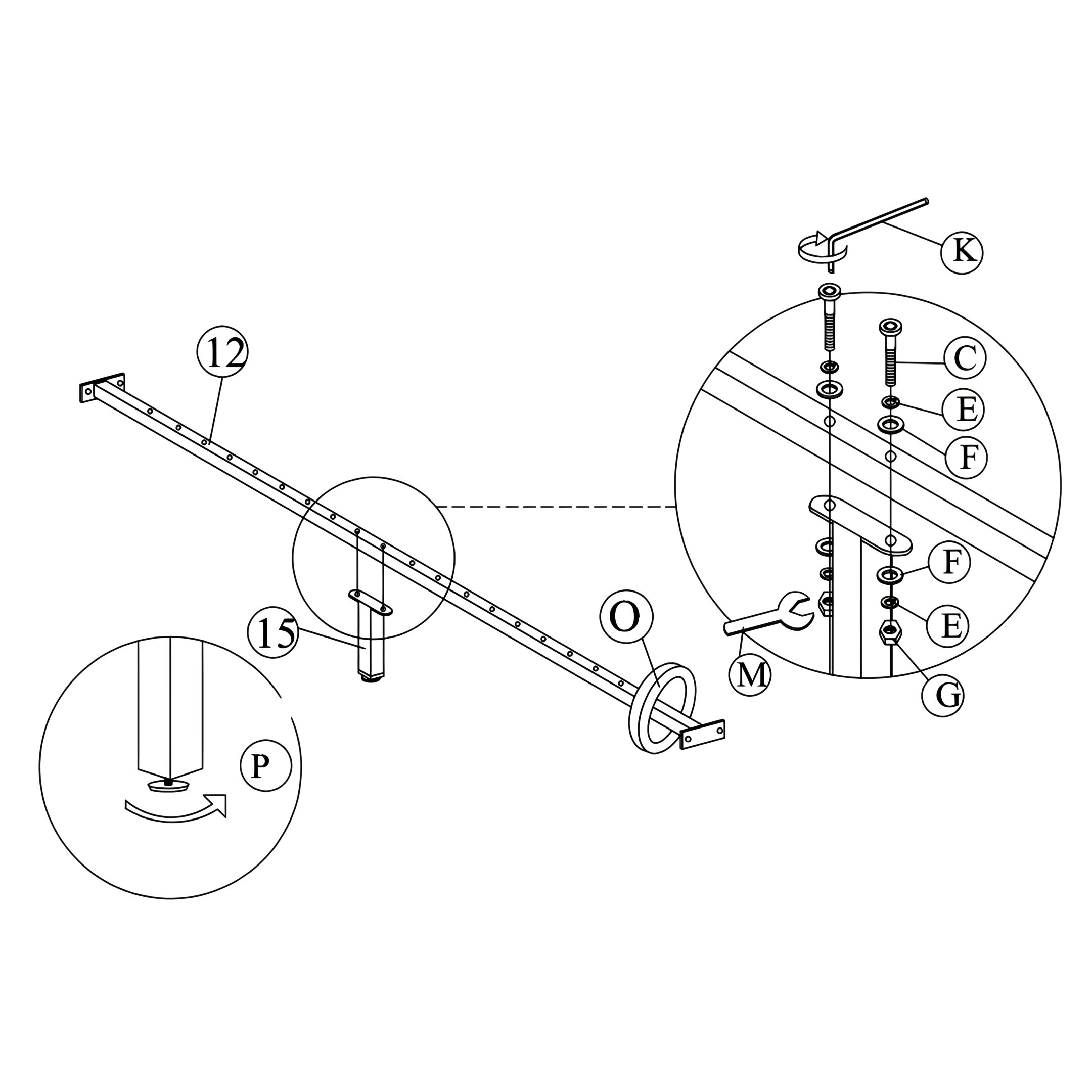
10. Installing the Support Leg
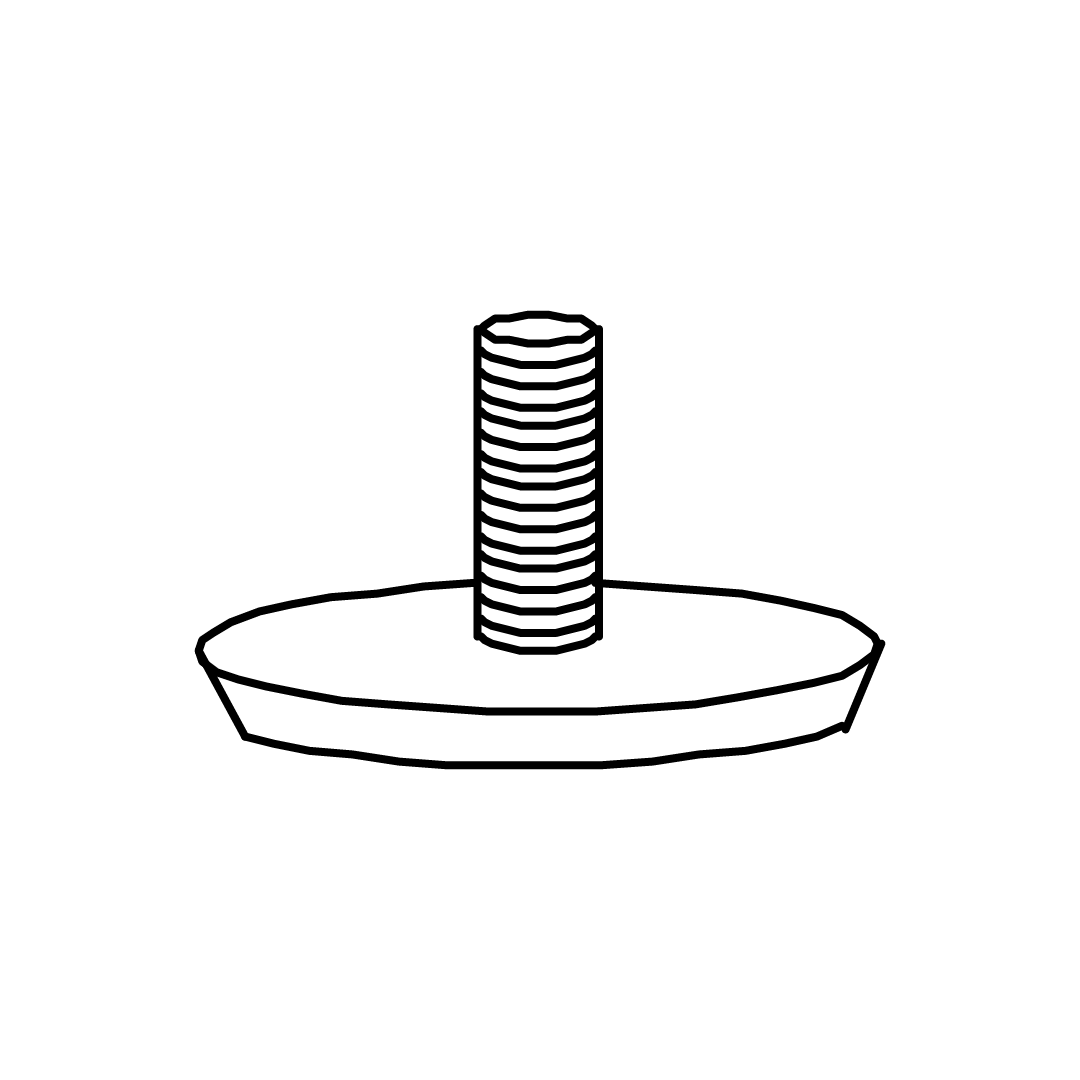
1. Position the Frame Lifter (O) at the designated location on the rail. 2. Install the Support Leg (15), secure the leg in place beneath the frame lifter. Use JCBC M6 X 50 screws (C), M6 Spring Washers (E), M6 Flat Washers (F), and M6 Hex Nuts (G) to fasten to the rail. 3. Tighten using the M4 Allen Key (K) and M6 Spanner (M). 4. Place and rotate the Adjuster (P) to ensure the support leg is stable and properly aligned.
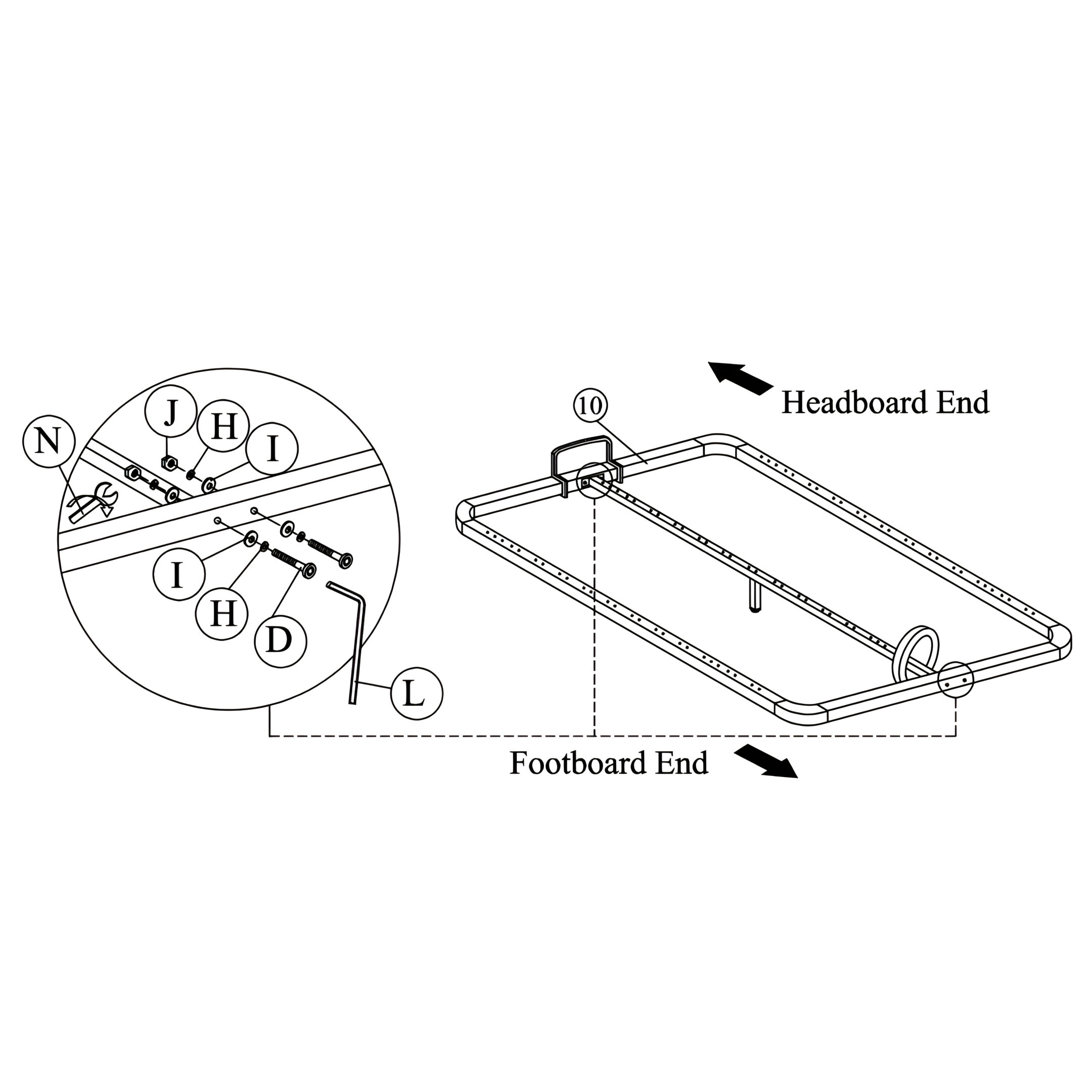
11. Attaching the Center Rail
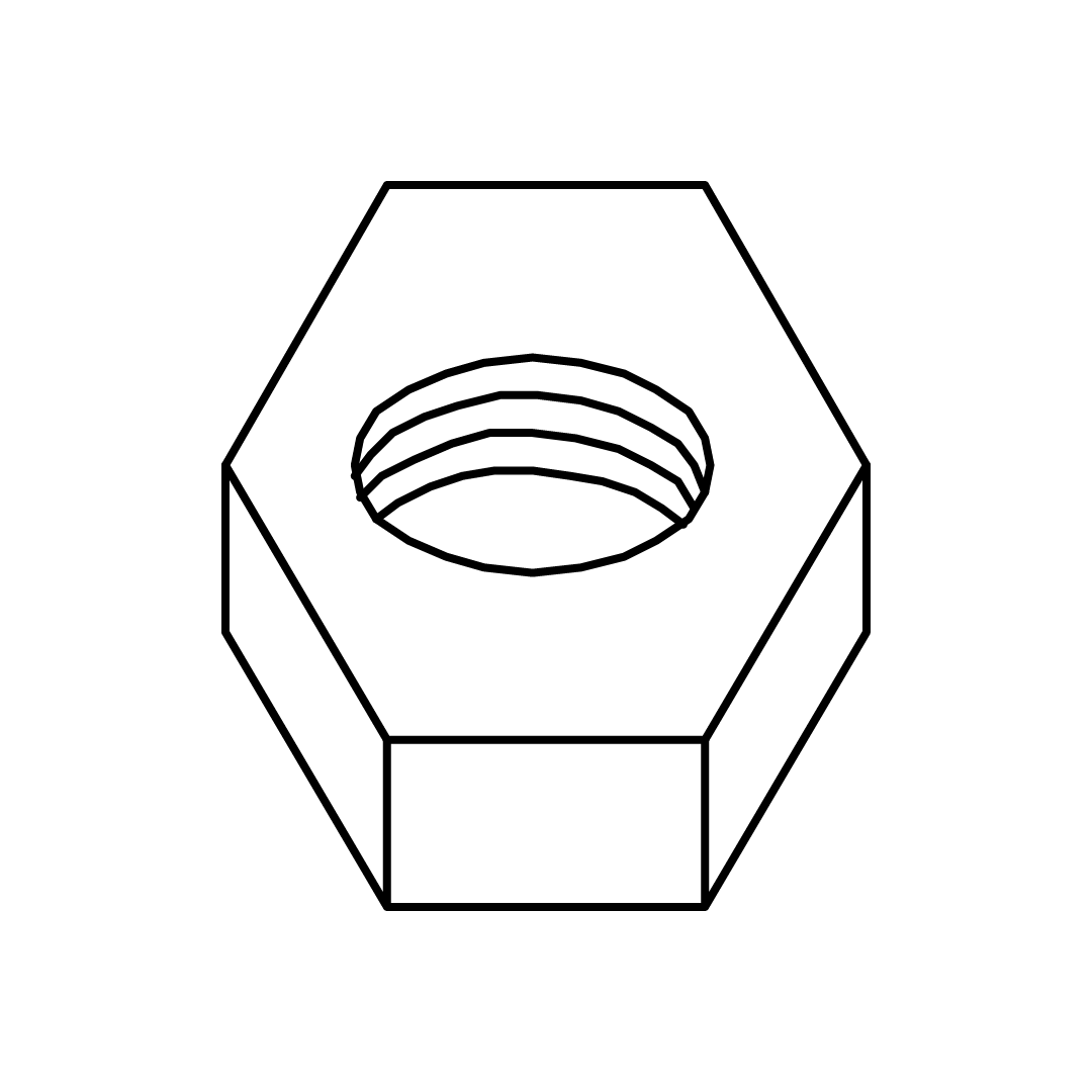
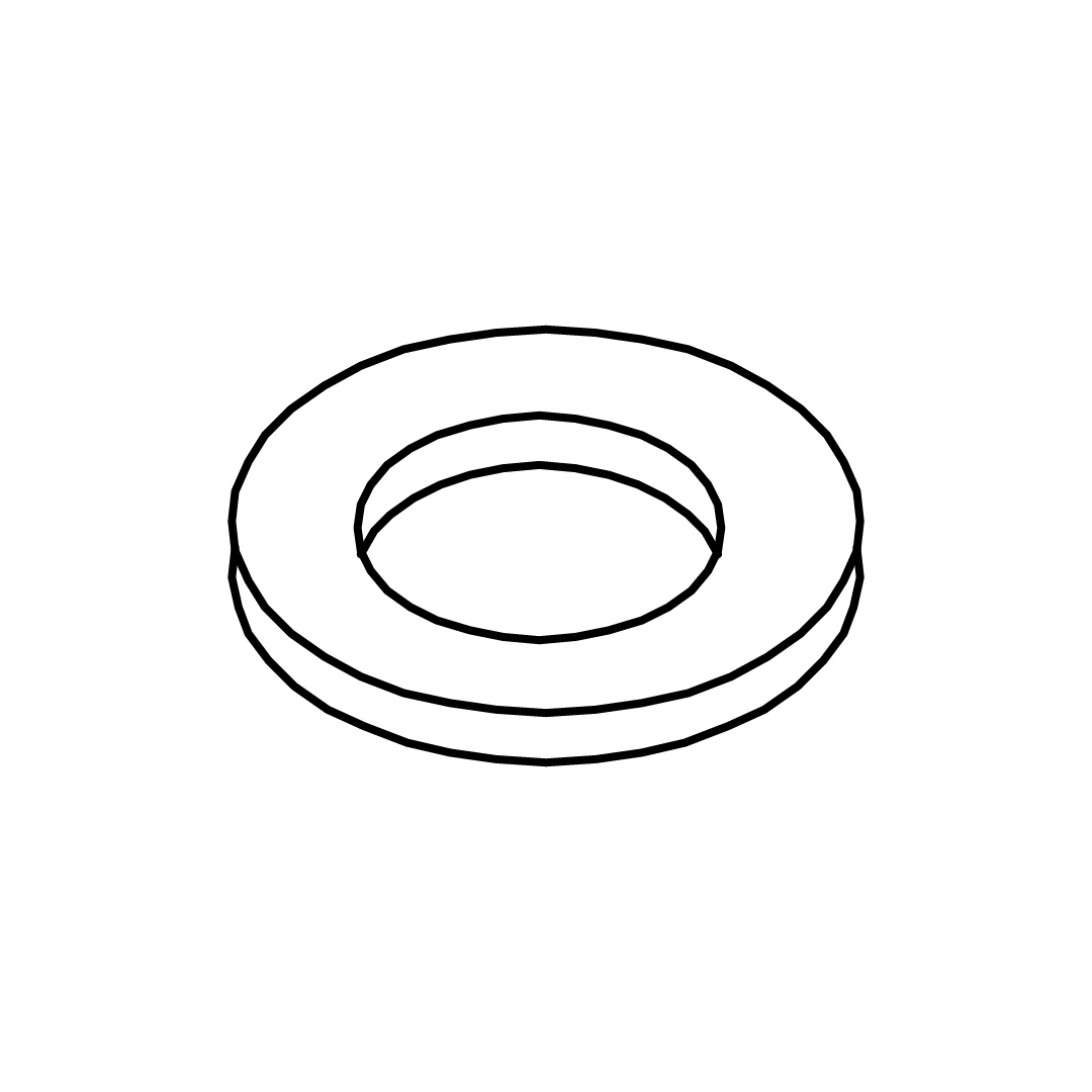
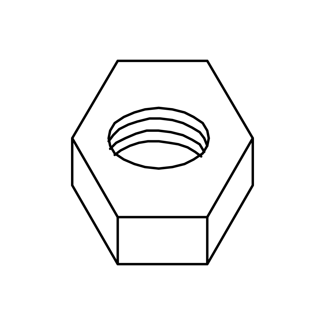
1. Align the Center Rail (12) with the pre-drilled holes in the Main Frame (10). 2. Secure with hardware, use JCBB M8 X 50 screws (D), M8 Spring Washers (H), M8 Flat Washers (I), and M8 Hex Nuts (J). Tighten using the M5 Allen Key (L) and M8 Spanner (N).
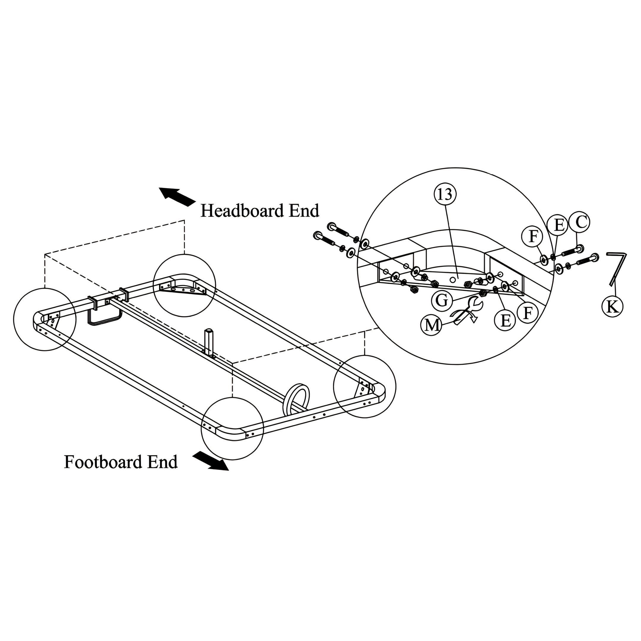
12. Attaching the Metal Corner Brackets
1. Position the Metal Corner Brackets (13), align the brackets at the designated locations on the frame. 2. Secure with hardware, use JCBC M6 X 50 screws (C), M6 Spring Washers (E), M6 Flat Washers (F), and M6 Hex Nuts (G). Tighten using the M4 Allen Key (K) and M6 Spanner (M).
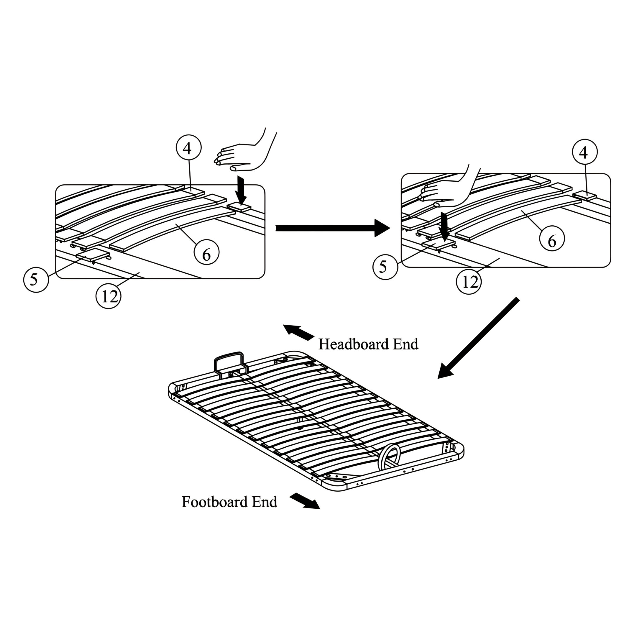
13. Installing the Slats
1. Attach the Slat End Holders (4) to the Slats (6), then secure them to the Side Rails. 2. Attach the Slat Middle Holders (5) to the Slats (6), then secure them to the Center Rail (12). 3. Position each Slat (6) over the designated slots and press them into place. 4. Secure the Slats (6) by firmly pushing them into the End Holders (4) and Middle Holders (5) to lock them in position.
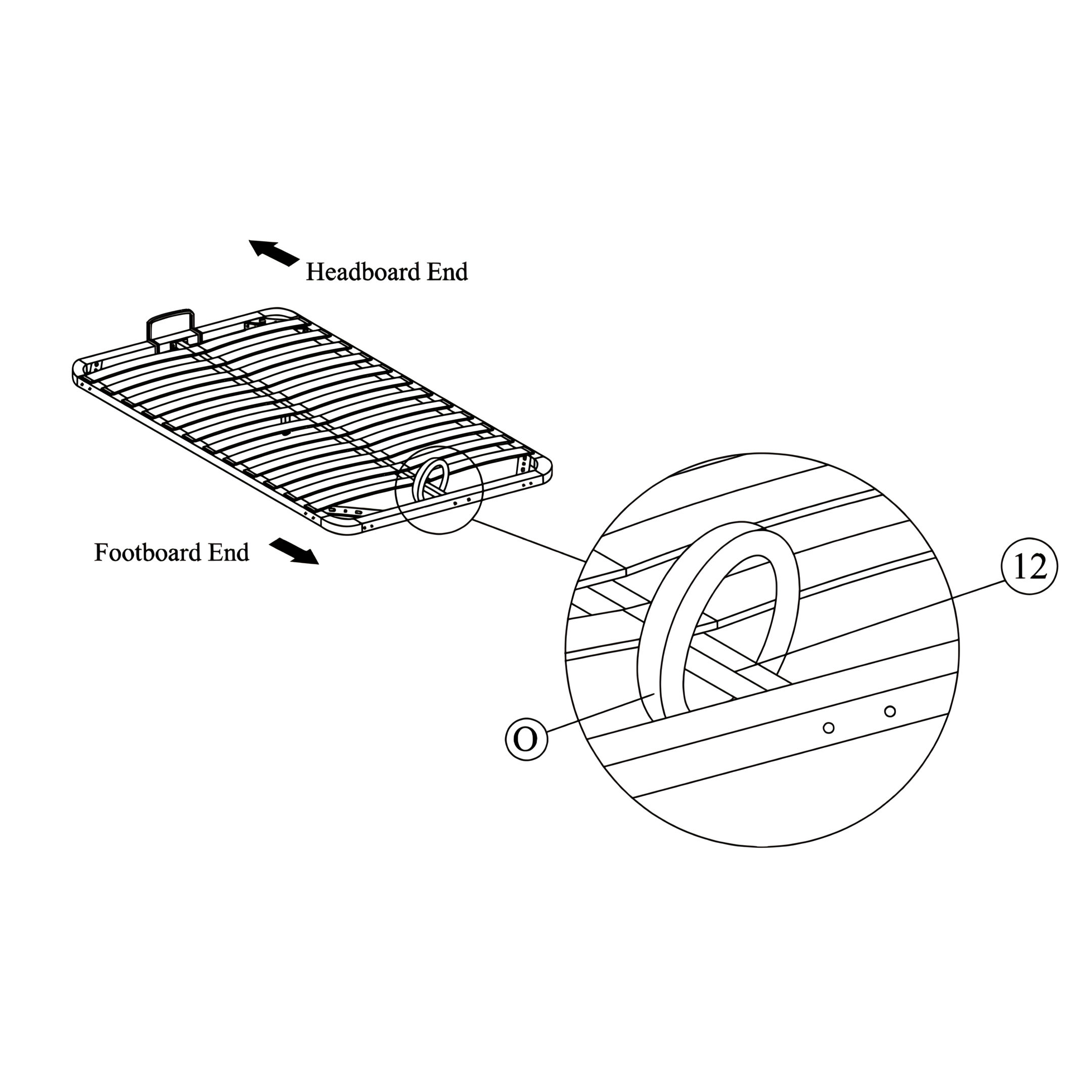
Align the Fabric Loop (O), position the loop at the designated location on the Center Rail (12). Check that the loop is firmly in place and ready for use.
Note: The Frame Lifter (O) is a fabric loop, not a rigid part.
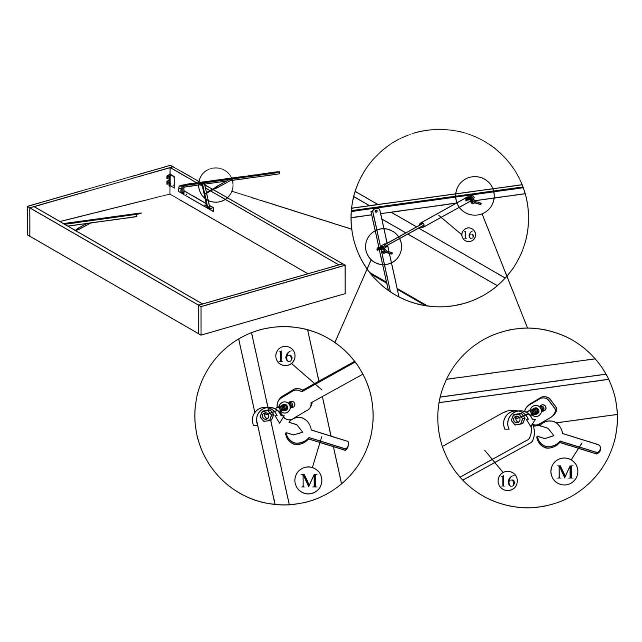
15. Installing the Gas Springs
1. Align the Gas Springs (16), position the gas springs at the designated attachment points on the bed frame. 2. Attach each gas spring using the provided bolts and tighten them with the M6 Spanner (M). 3. Ensure both gas springs are securely fixed and aligned correctly for smooth operation.
Important: Do not overtighten the bolts to allow proper movement of the gas springs.
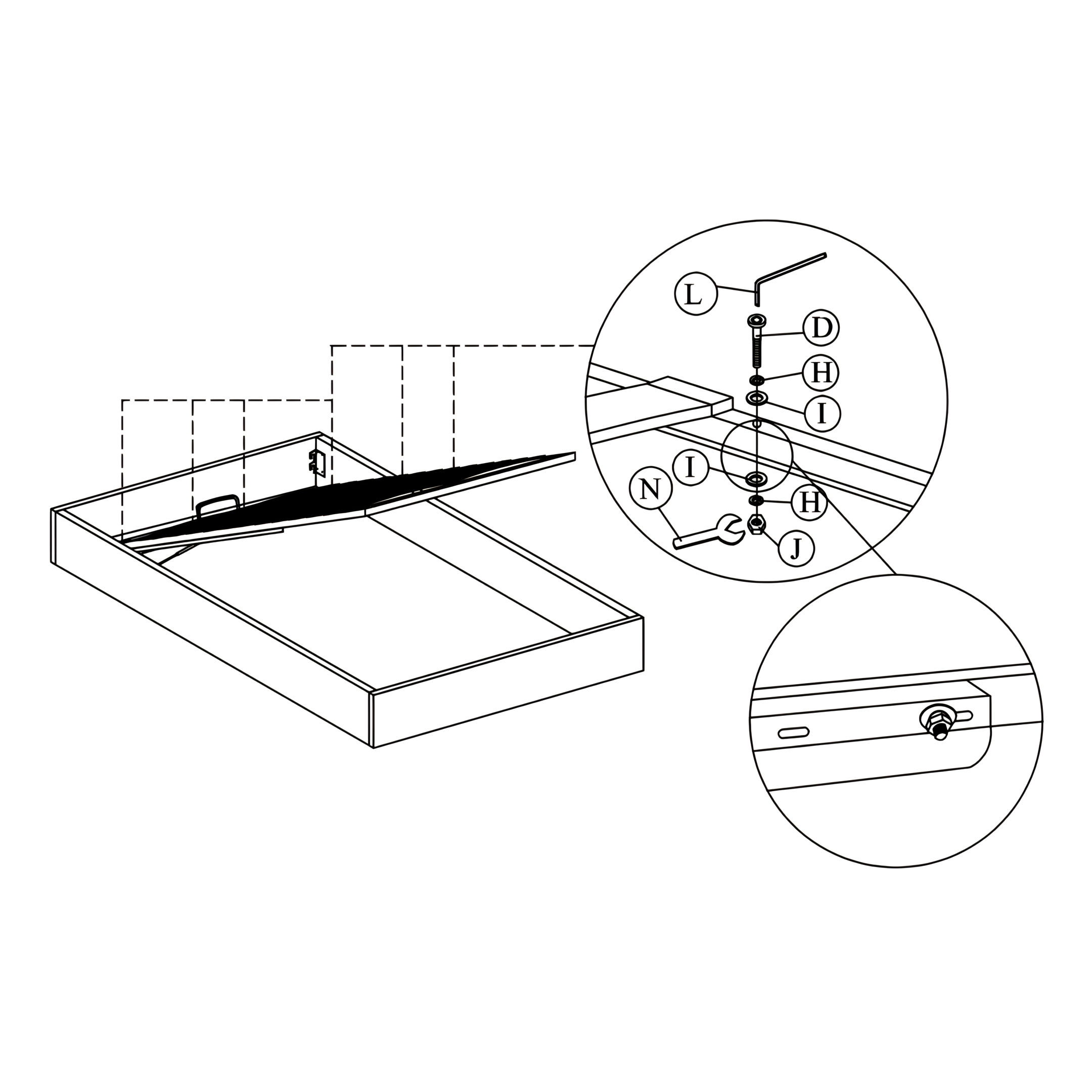
16. Securing the Gas Springs and Final Adjustments
1. Align the gas springs with the designated mounting points on the bed frame. 2. Secure with hardware, use JCBB M8 X 50 screws (D), M8 Spring Washers (H), M8 Flat Washers (I), and M8 Hex Nuts (J). Tighten using the M5 Allen Key (L) and M8 Spanner (N). 3. Ensure the gas springs are securely attached and can move smoothly to support the lifting mechanism.