Assembly instructions for the Oslo 1 Drawer Dressing Table.
Product Information
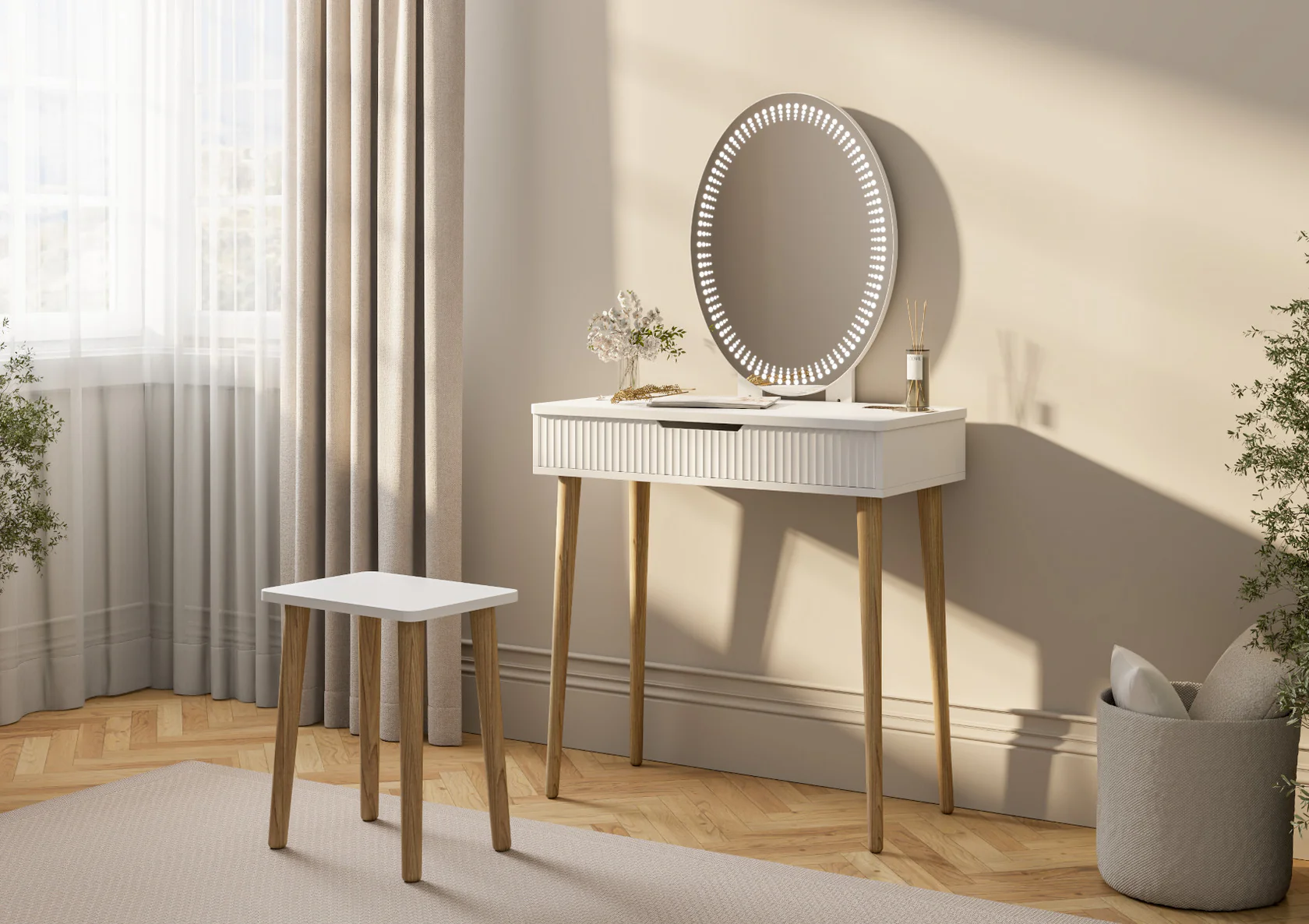
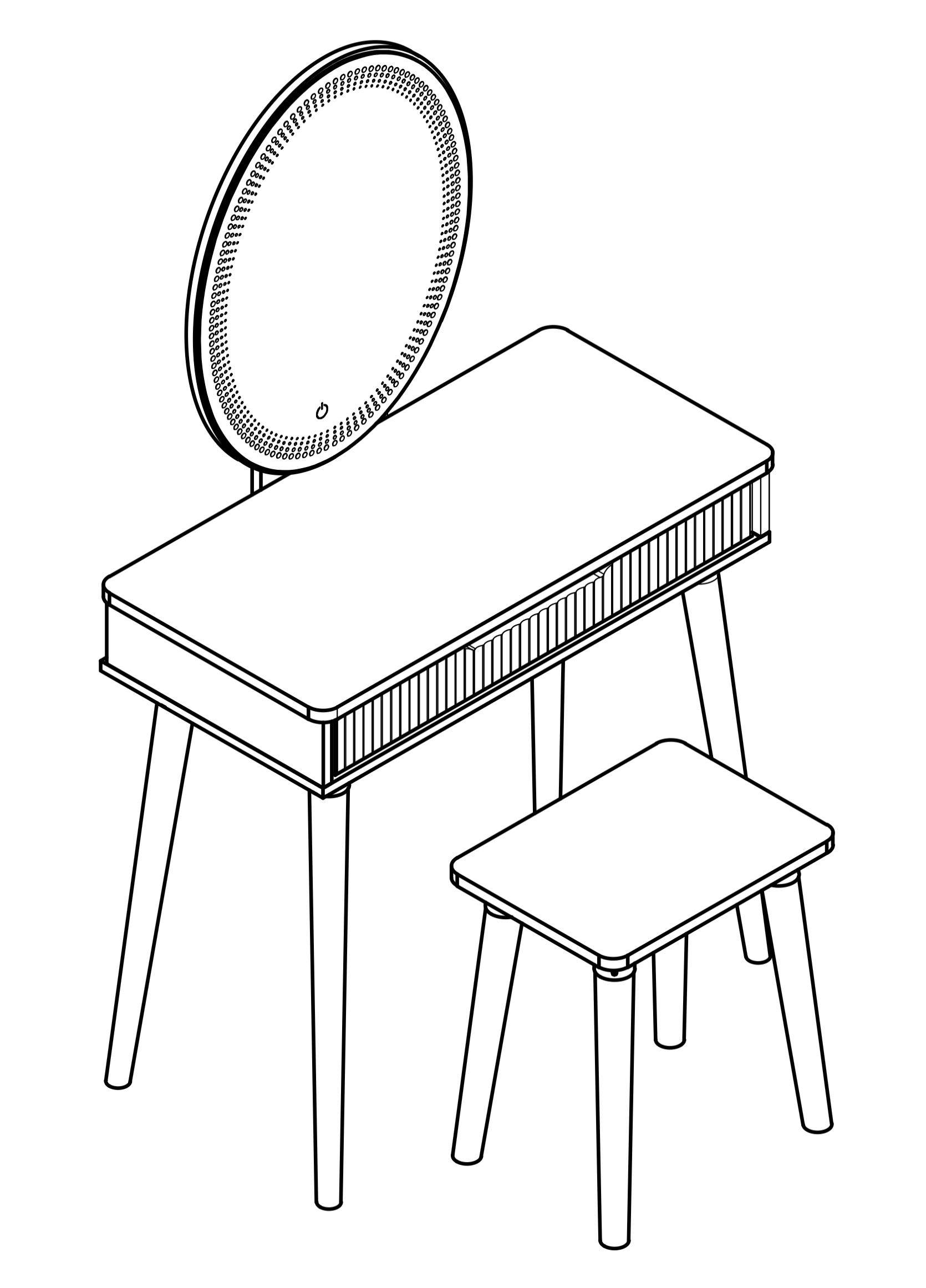
Oslo 1 Drawer Dressing Table
Inspired by the simplicity and beauty of Scandinavian design, the Oslo Dressing Table brings a touch of modern elegance to your space. Finished in a crisp white finish, it offers a clean, minimalist look, perfectly complemented by oak effect legs for a warm, natural contrast.
The LED mirror offers adjustable lighting ensuring the perfect ambiance for your makeup and skincare routine. A sculptured drawer front adds a subtle yet stylish texture to its sleek design whilst providing practical storage for your beauty essentials, keeping your space clutter-free while maintaining its contemporary charm.
Designed for both function and style, the Oslo Dressing Table is the perfect addition to any modern bedroom or dressing area, blending effortlessly with a range of interiors to create a fresh, airy feel.
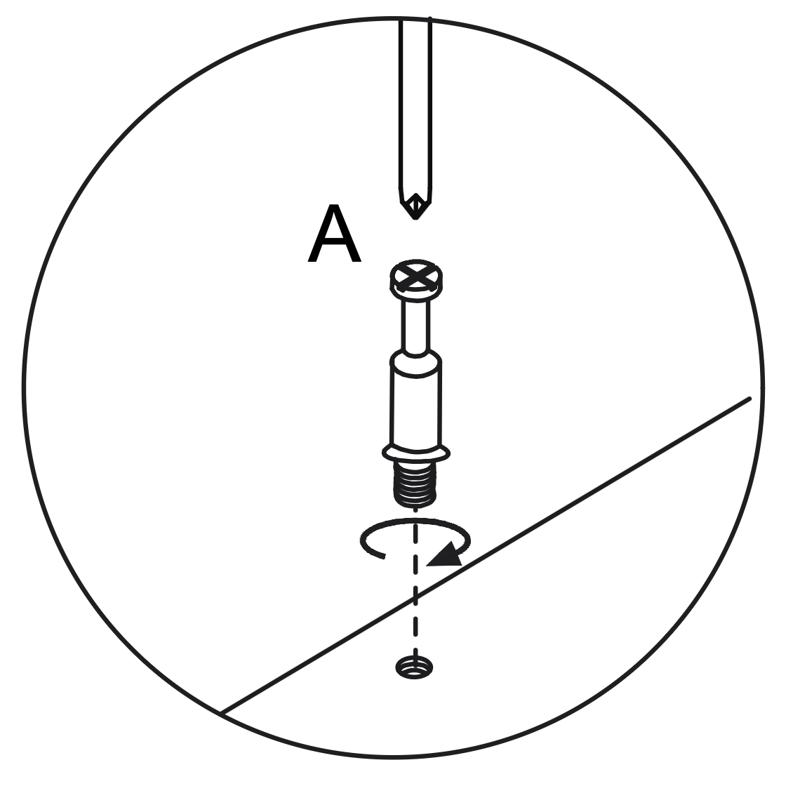
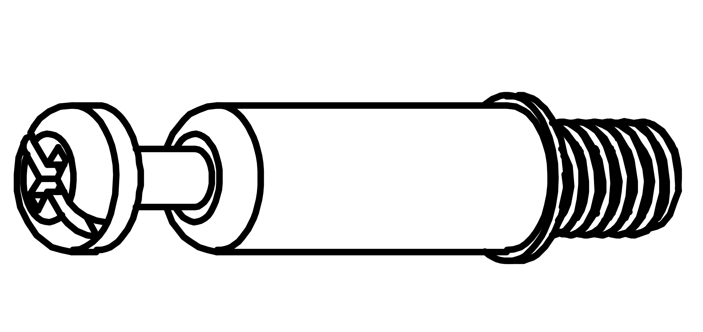
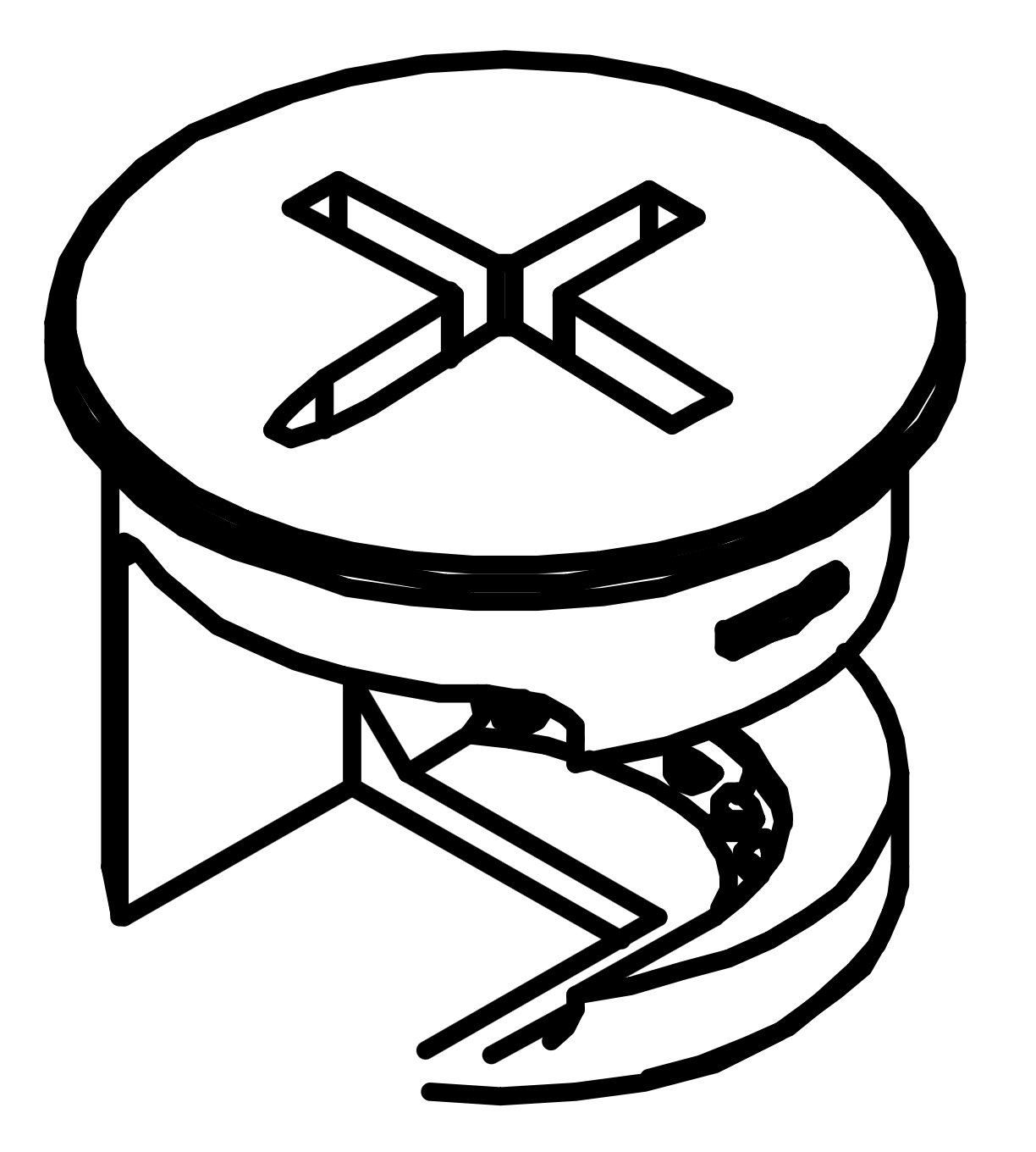
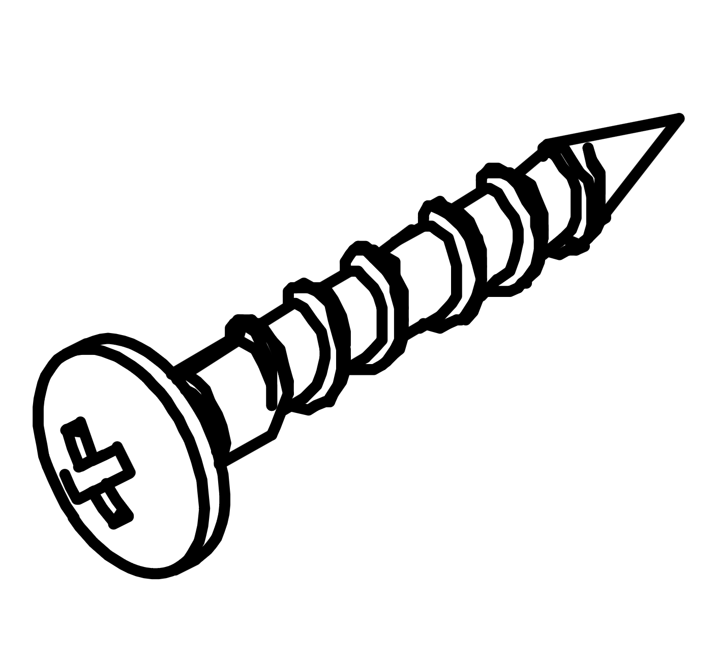
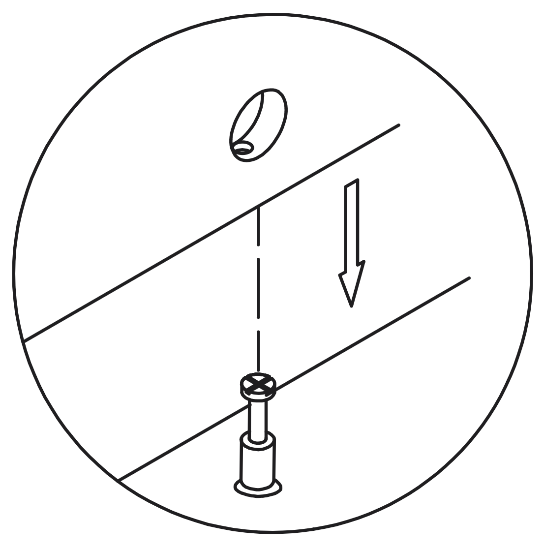
Insert the Cam Dowel (A) into the designated hole on the panel.
Use a screwdriver to turn the dowel clockwise until it is fully inserted and level with the surface, ensuring it extends 35mm above the panel.
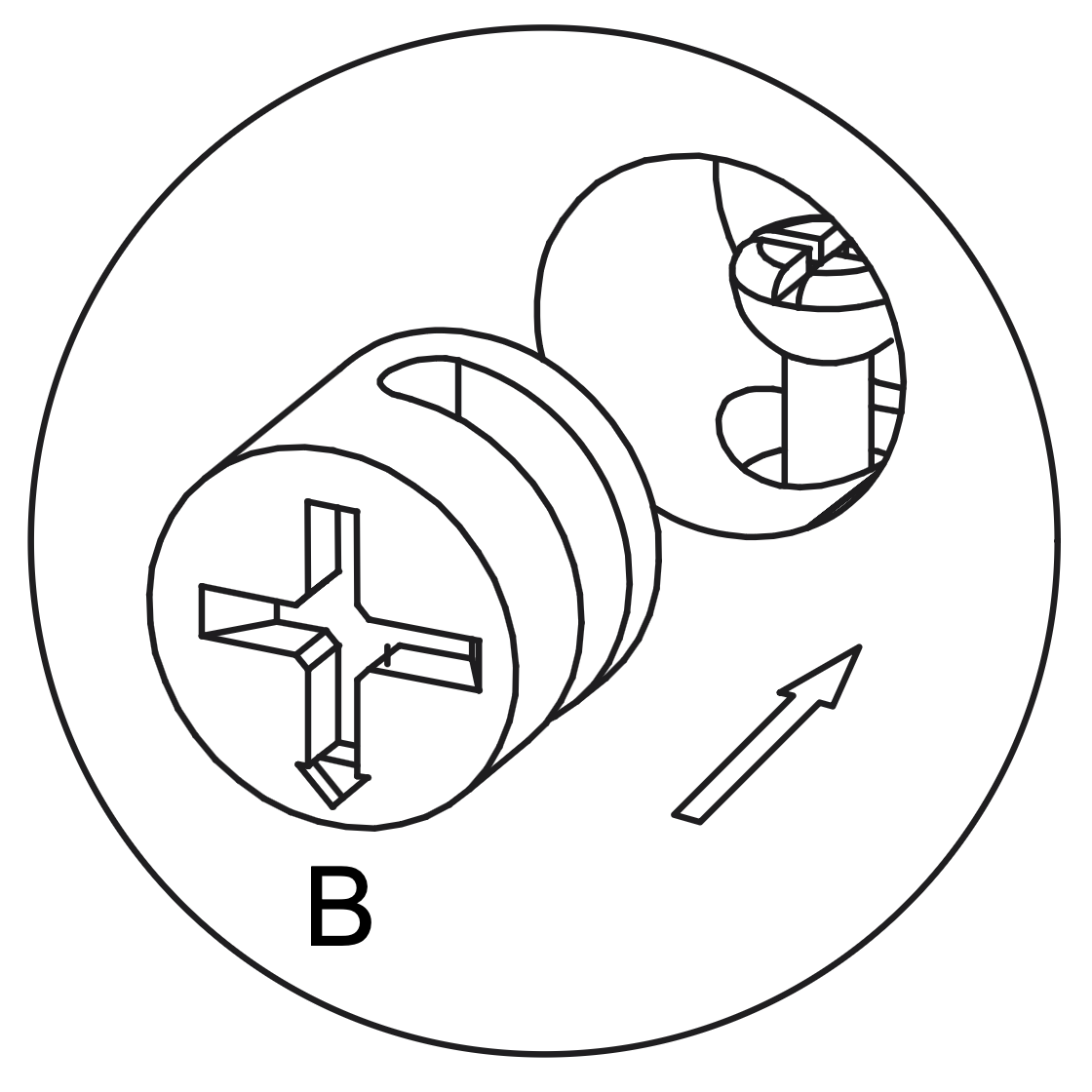
2. Working with Cam Locks
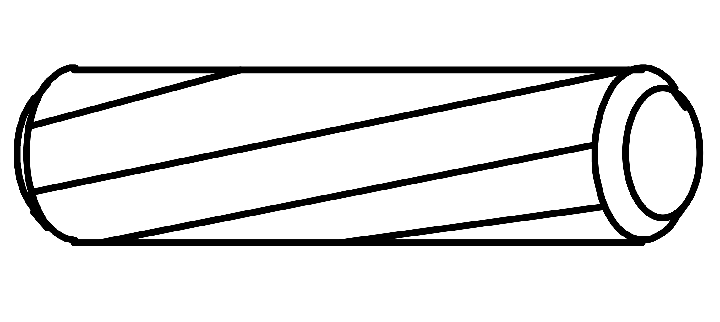
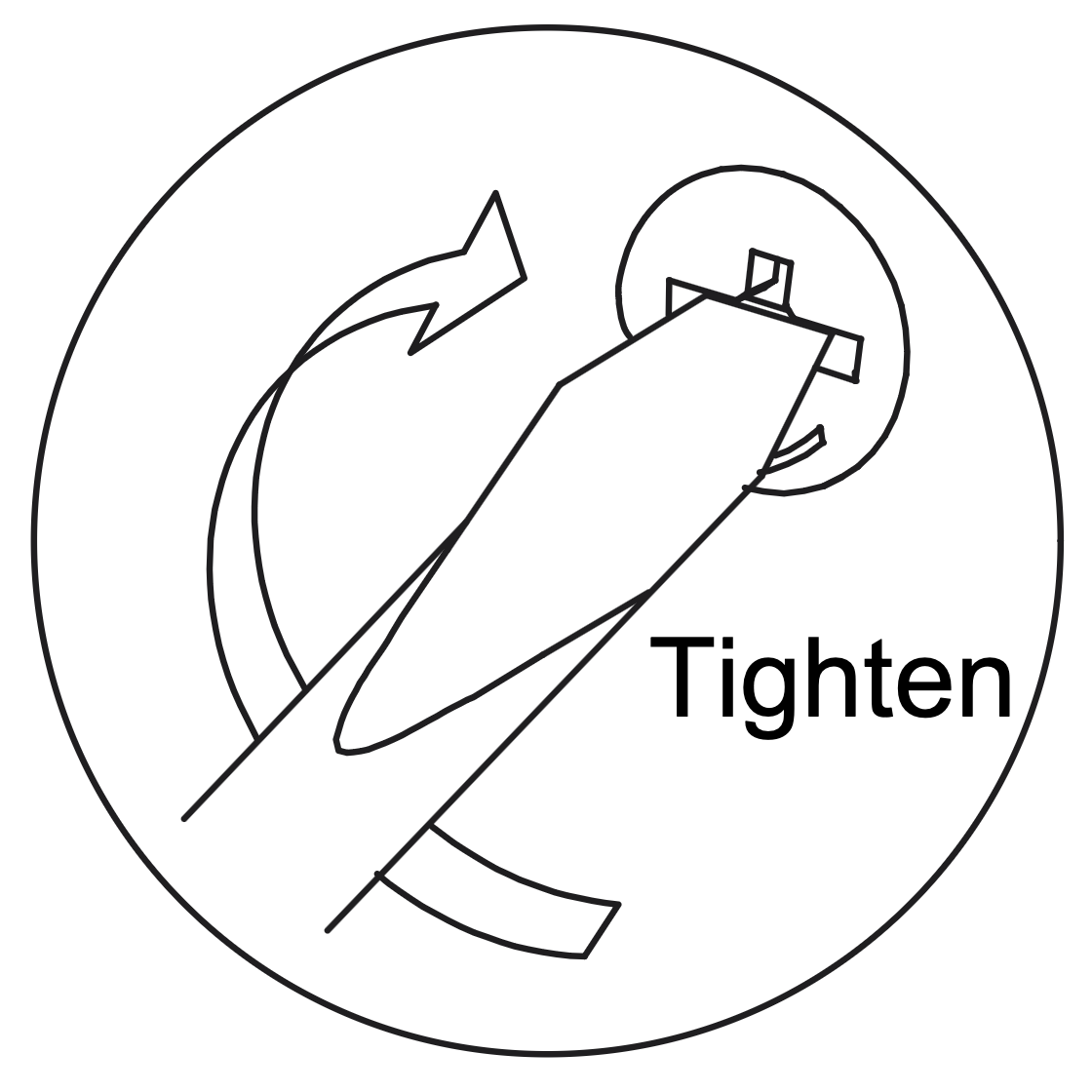
Insert the Cam Lock (B) into the designated hole on the panel, aligning it with the Cam Dowel (A).
Use a screwdriver to turn the Cam Lock clockwise until it is securely tightened, ensuring a firm connection between the panels.
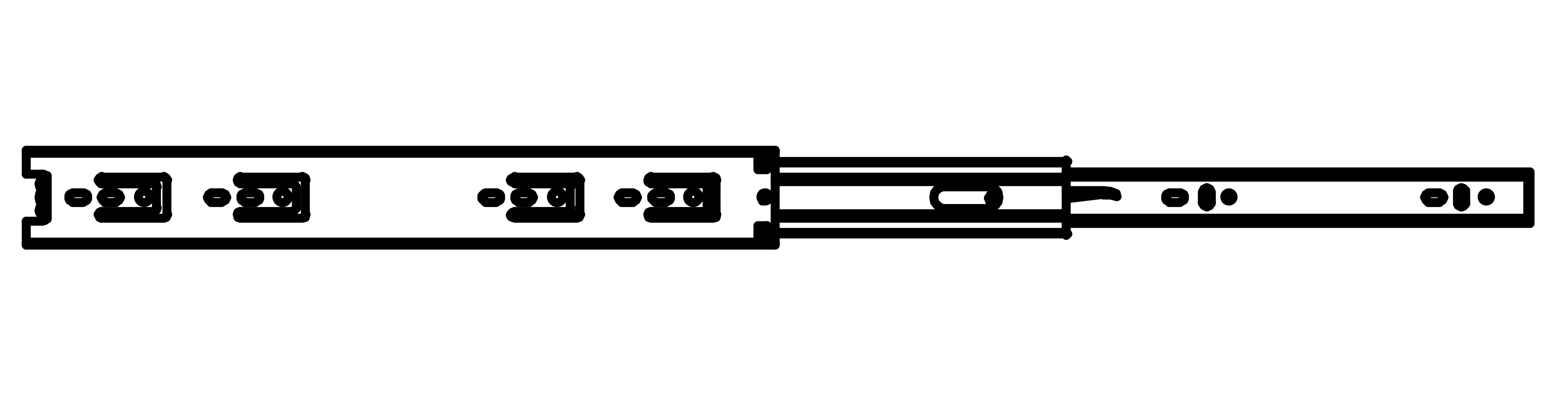
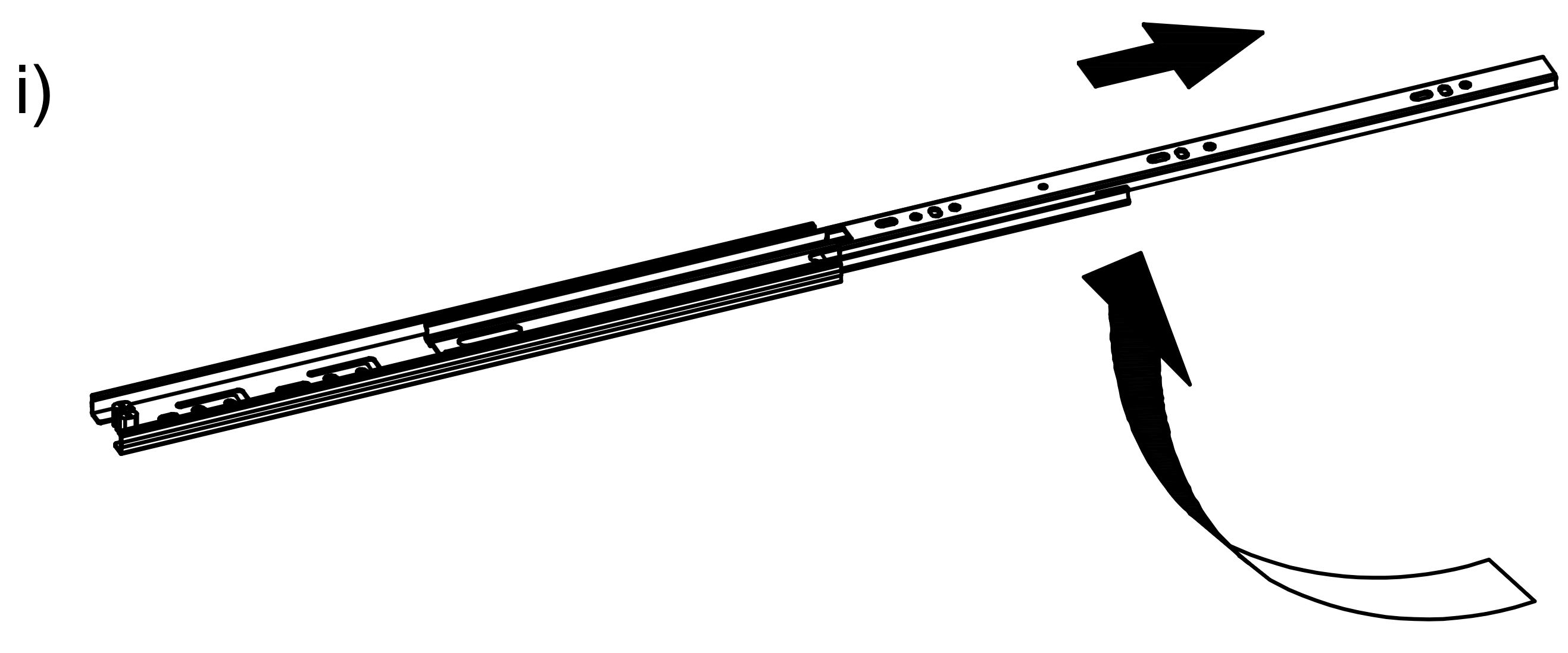
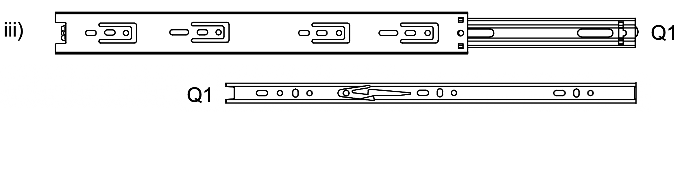
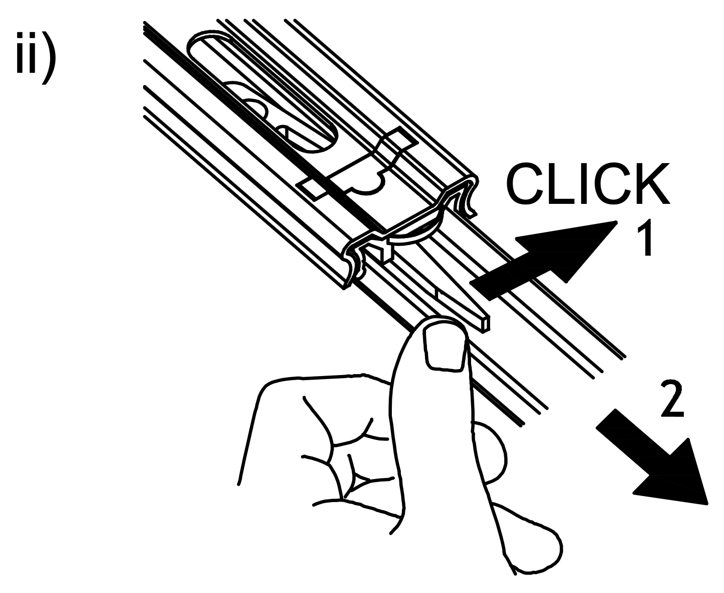
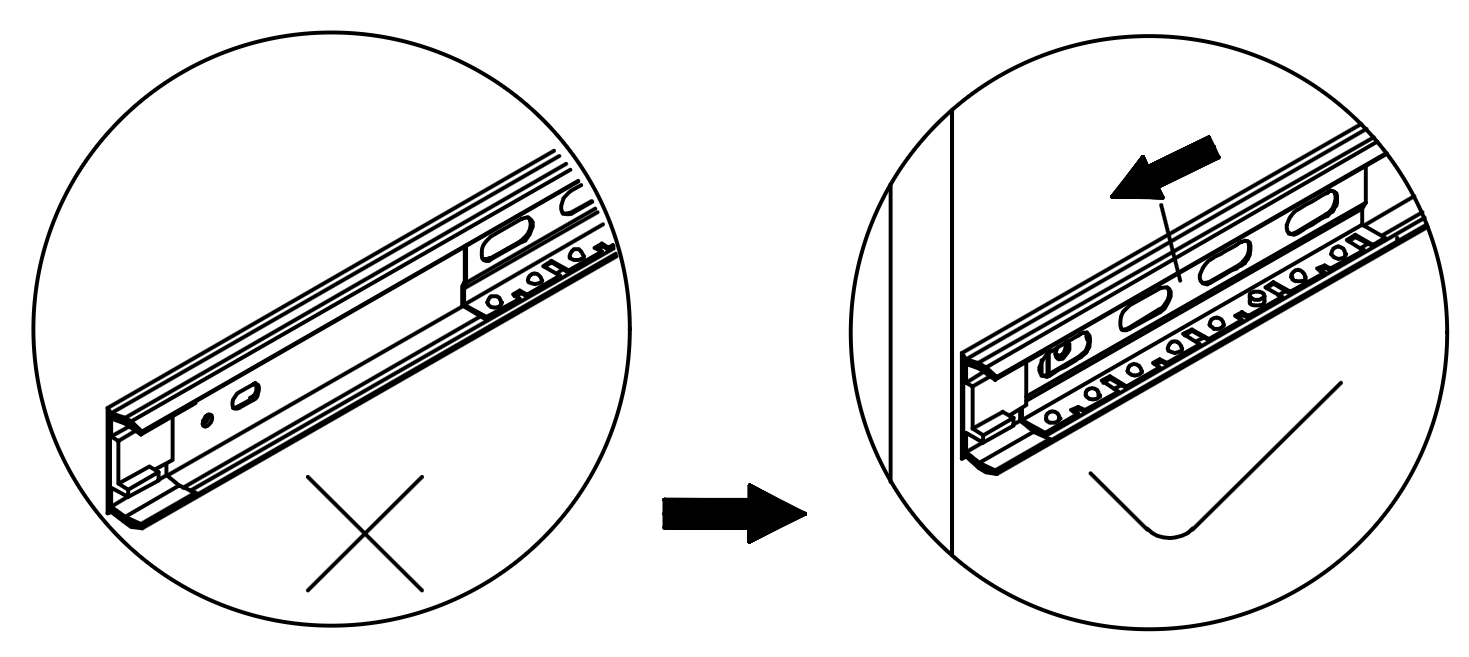
3. Separate the Runner (Q)
1. Extend the Runner (Q) by pulling it outwards as shown in the first image. 2. Press the release lever on the runner to separate the two parts, ensuring a "click" sound is heard to confirm detachment. 3. Identify the two parts of the Runner (Q1) and prepare them for installation on the drawer and the side panel.
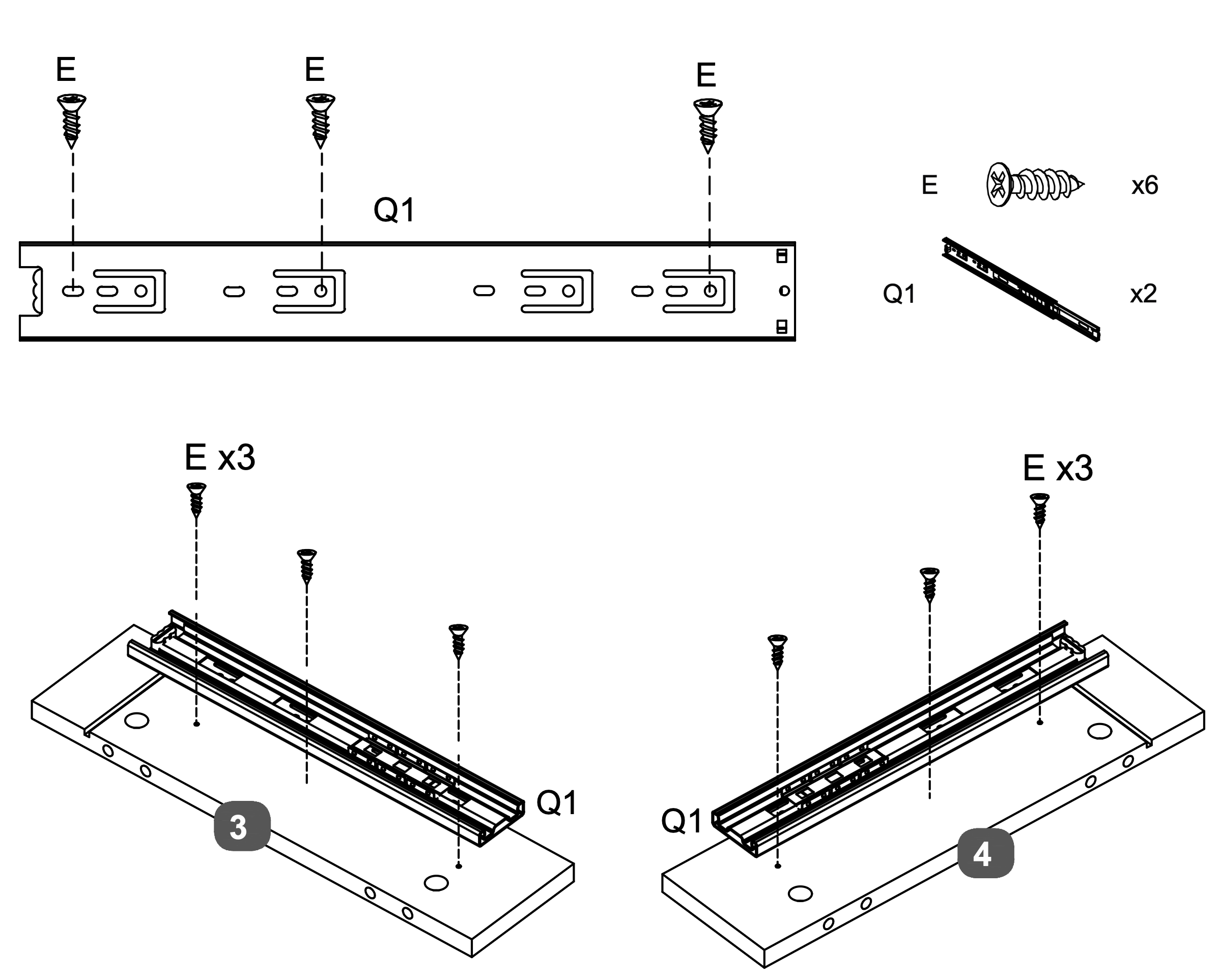
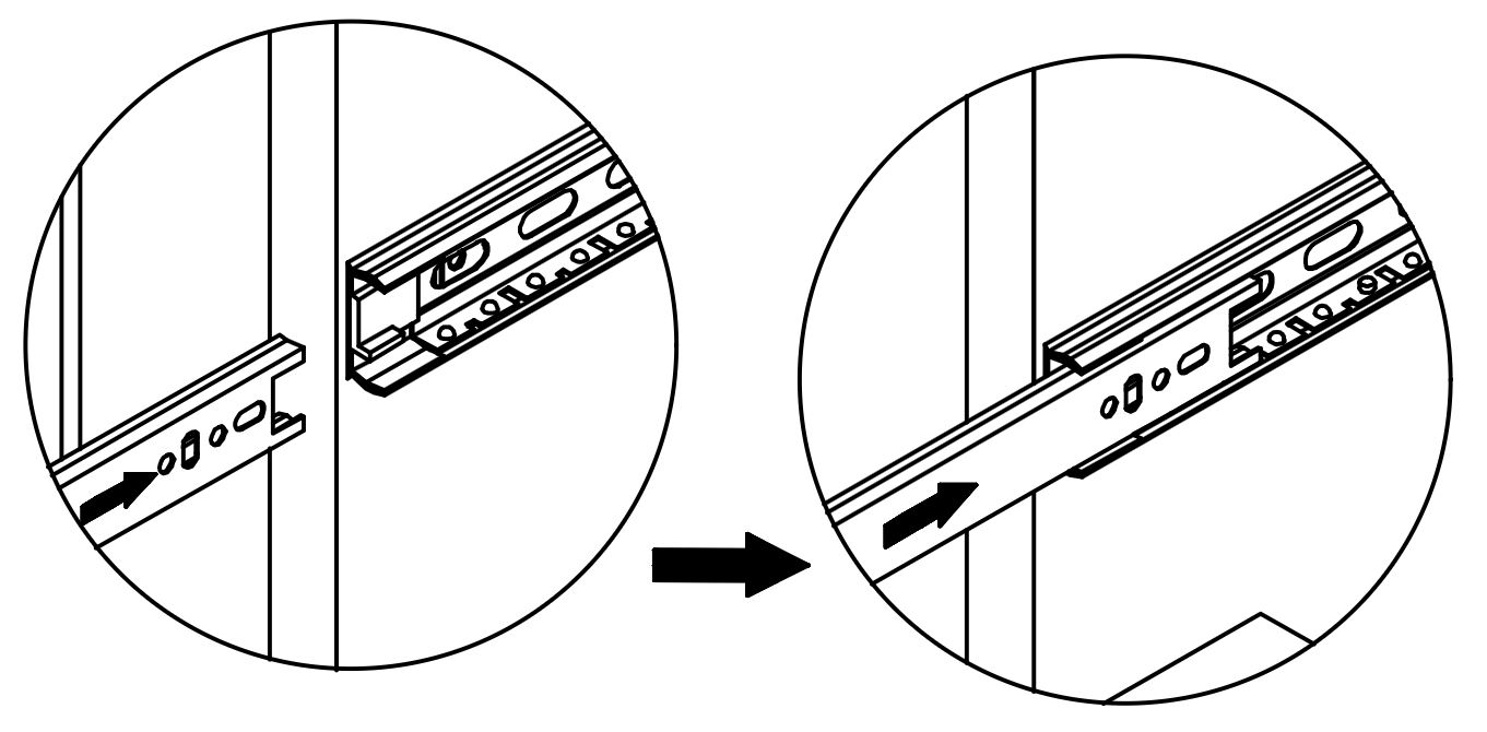
4. Runner Attachment and Alignment
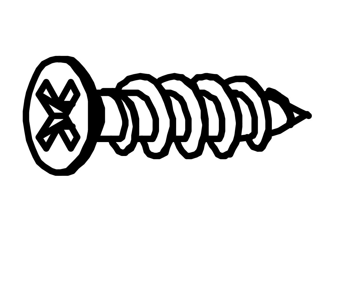
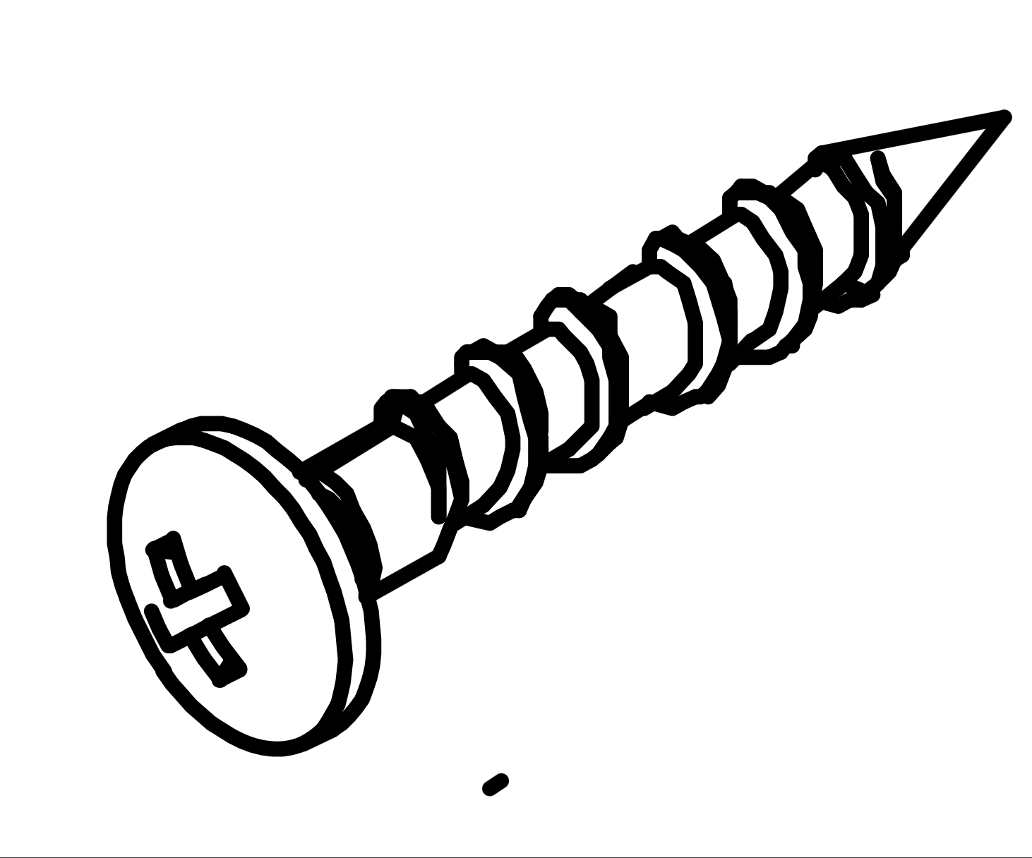
Attach the Runner (Q1) to the designated panel using three Screws (E).
Align the runner with the pre-drilled holes and secure it by inserting the screws through the runner into the panel.
Repeat this process for both panels, ensuring the runners are firmly attached and aligned correctly.
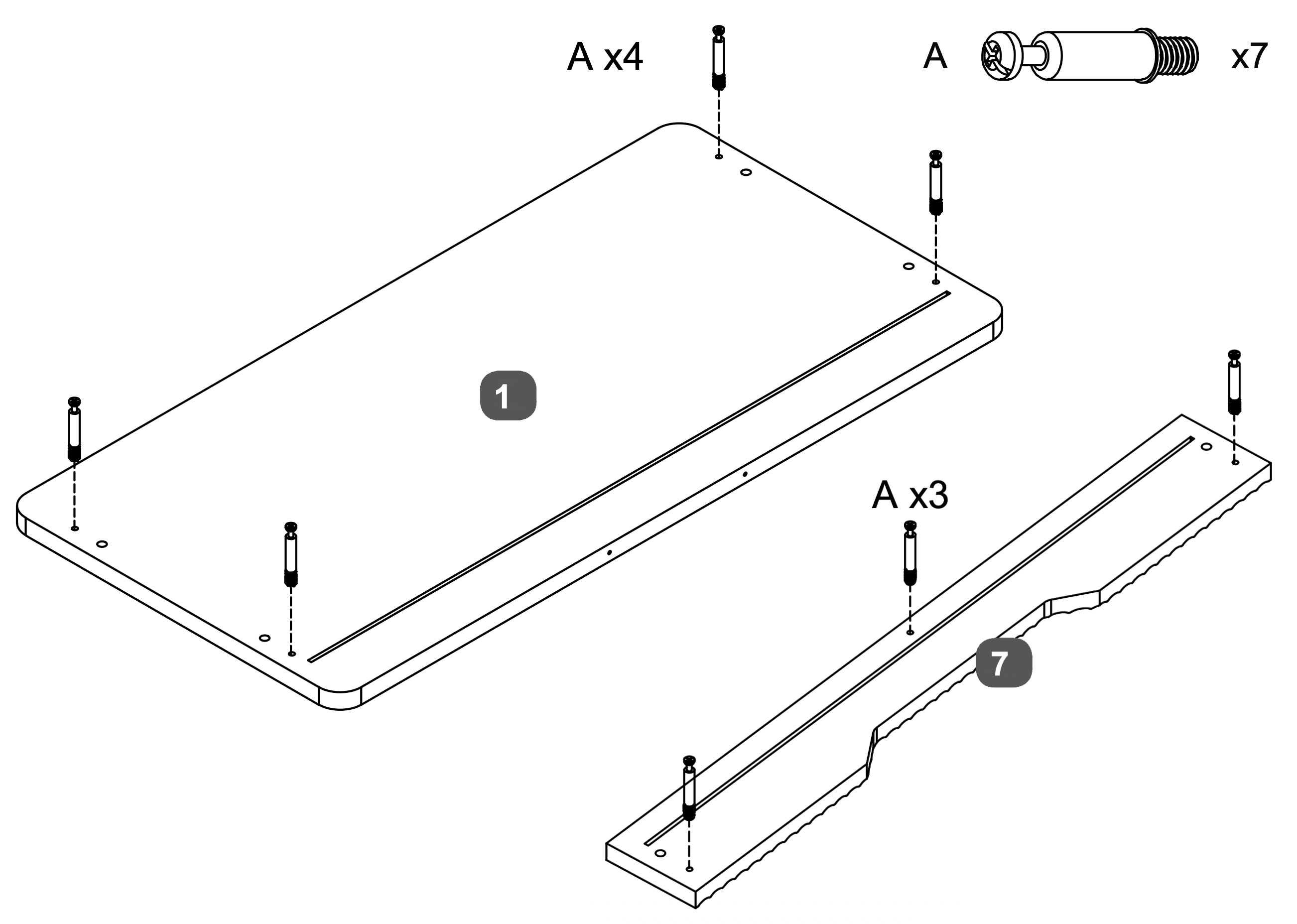
5. Dowel Insertion and Leveling
Insert four Cam Dowels (A) into the designated holes on the Top Panel (1).
Insert three Cam Dowels (A) into the designated holes on the Drawer Facia Panel (7).
Use a screwdriver to turn each dowel clockwise until fully inserted and level with the surface, ensuring they extend 35mm above the panels.
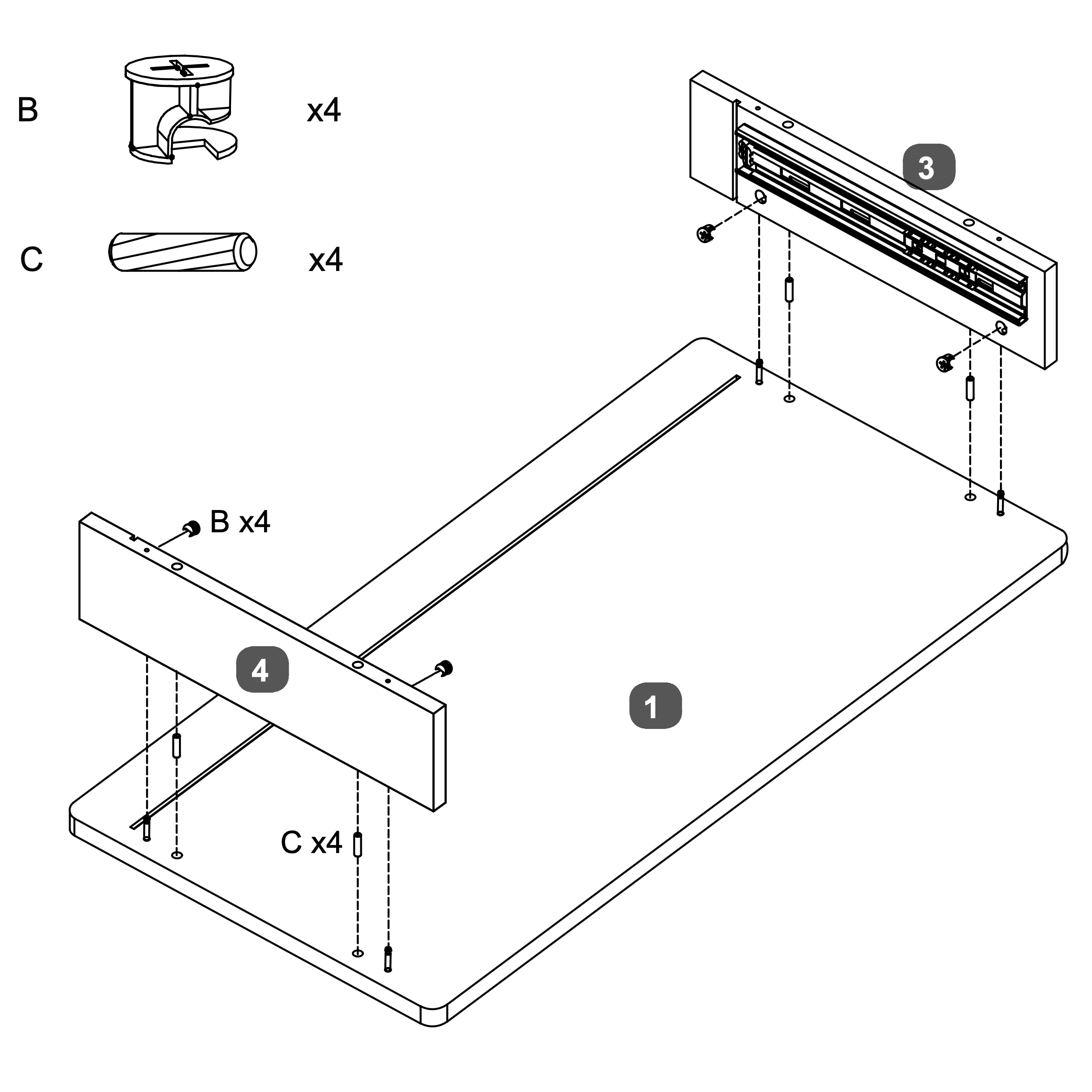
6. Component Alignment and Securing
1. Attach the Mirror Support Rail and Drawer Facia Panel:
* Insert four Dowels (C) into the designated holes on the Top Panel (1).
* Align the LH Side Panel (3) with the dowels and secure it using two Cam Locks (B).
* Similarly, align the RHB Side Panel (4) with the dowels on the opposite side and secure it using four Cam Locks (B).
* Ensure all components are firmly connected and aligned properly.
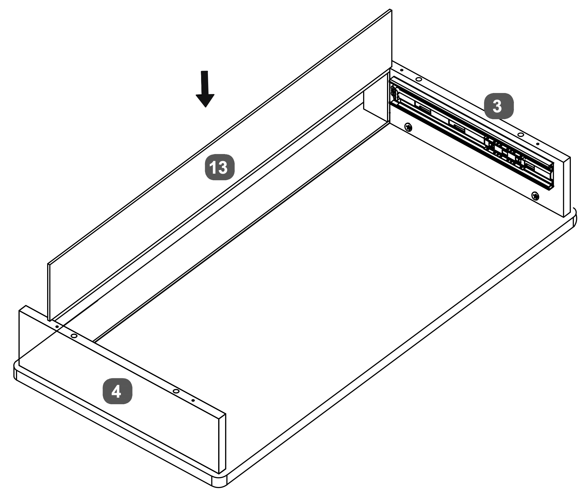
7. Panel Insertion and Securing
Insert the Drawer Back Panel (13) into the slots at the back of the Drawer Base Panel.
Ensure it fits securely between the LH Side Panel (3) and the RH Side Panel (4).
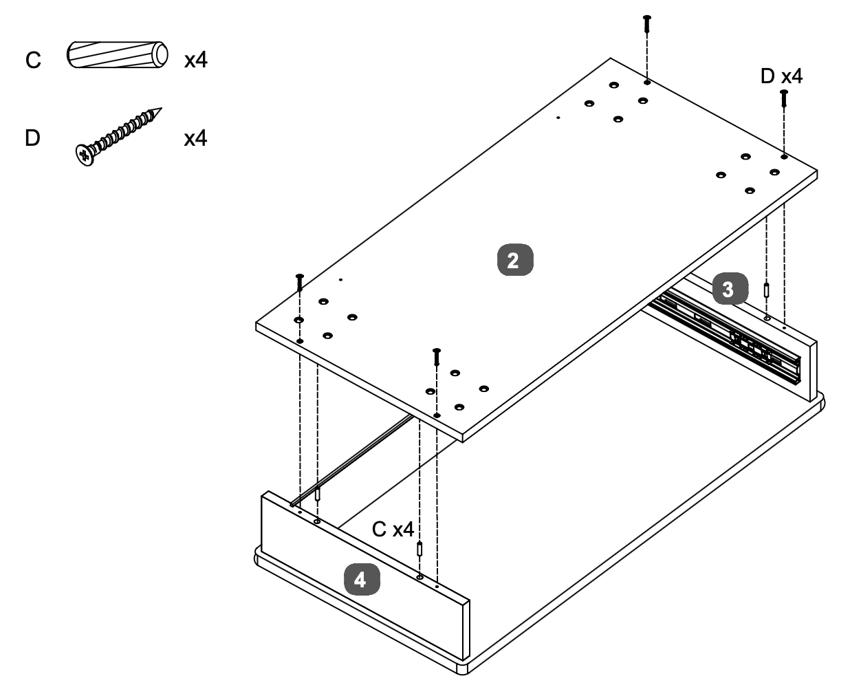
8. Panel Assembly and Securing
Insert four Dowels (C) into the designated holes on the RH Side Panel (4) and LH Side Panel (3)
Align the Base Panel (2) with the dowels and secure it using four Screws (D).
Ensure the Base Panel (2) is firmly attached and aligned with both side panels.
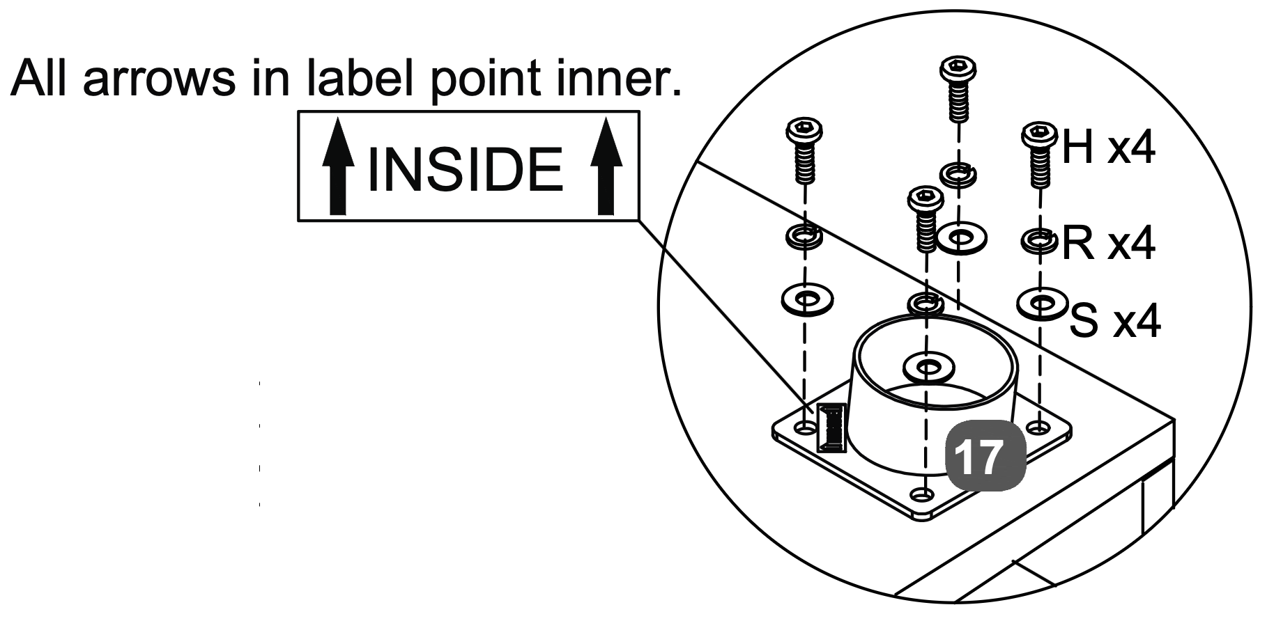
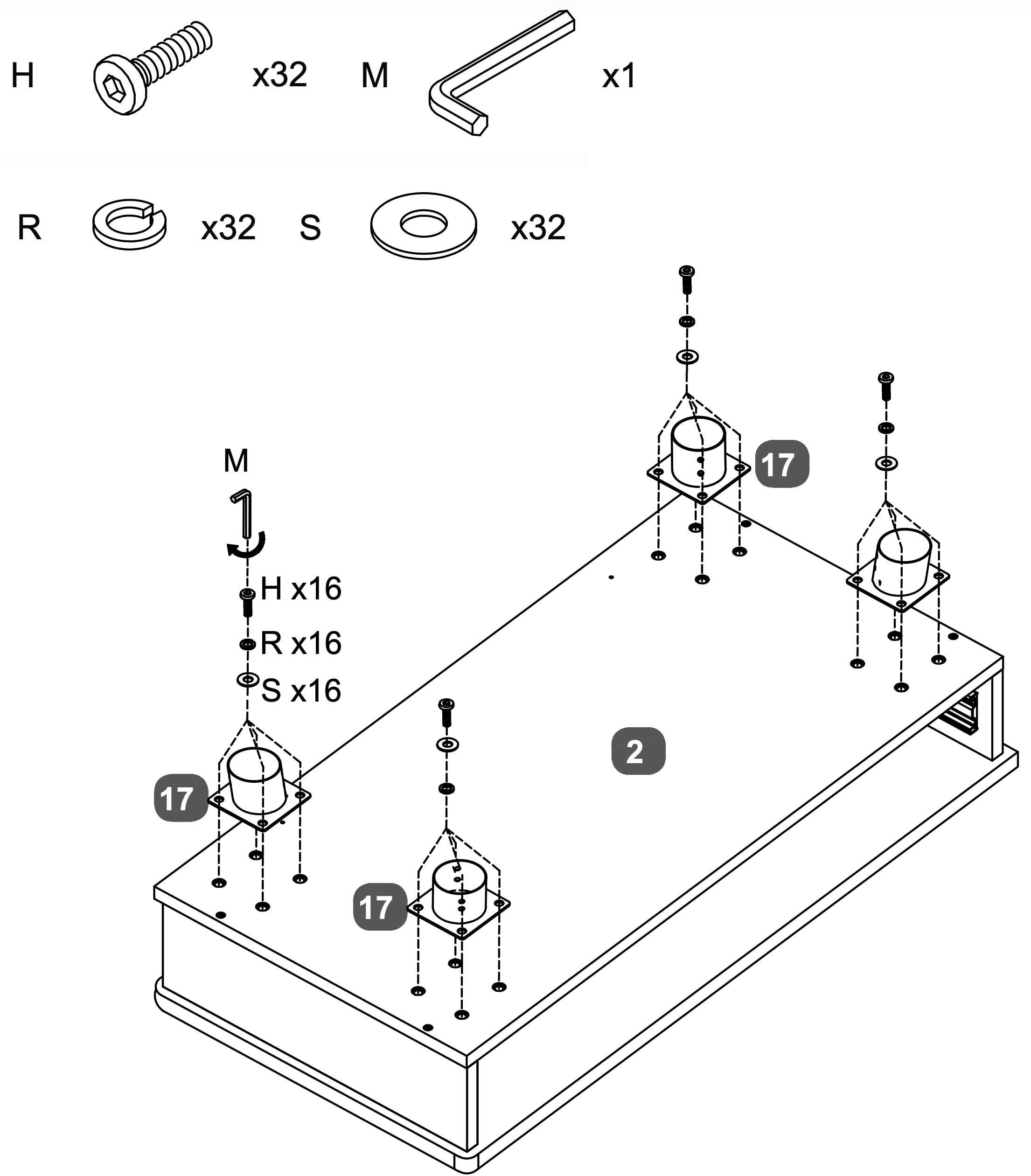
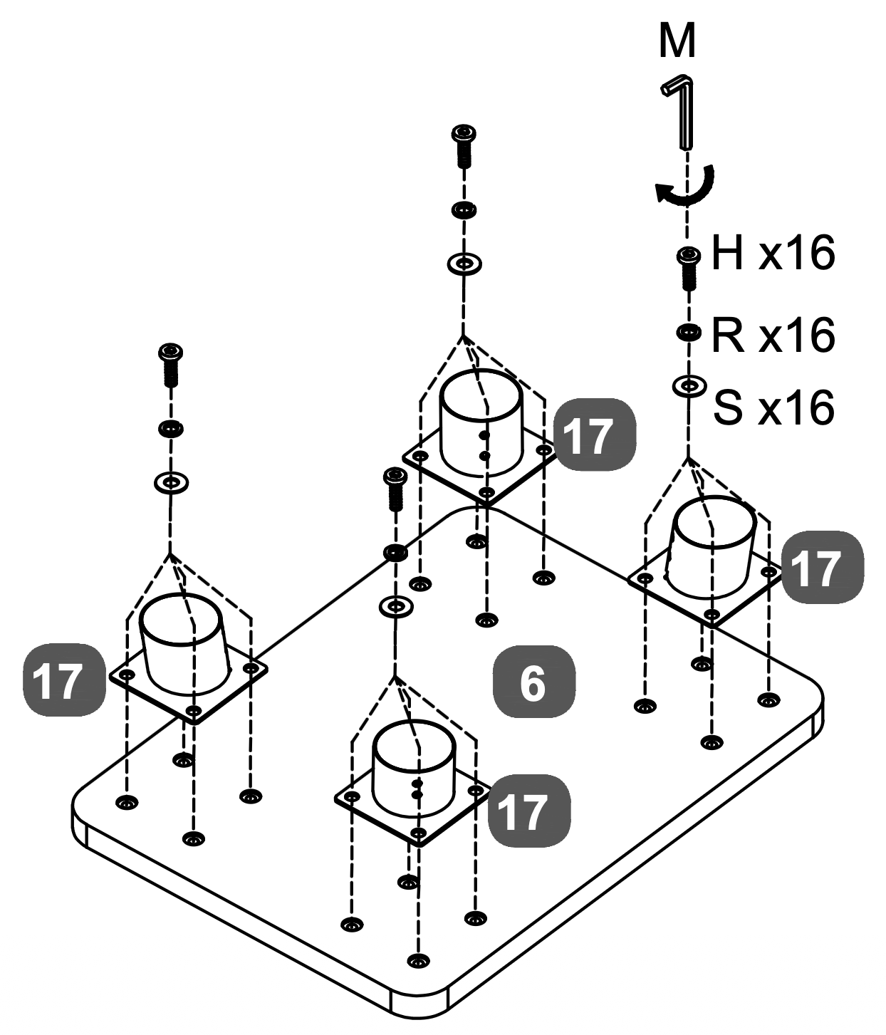
9. Bracket Attachment and Tightening
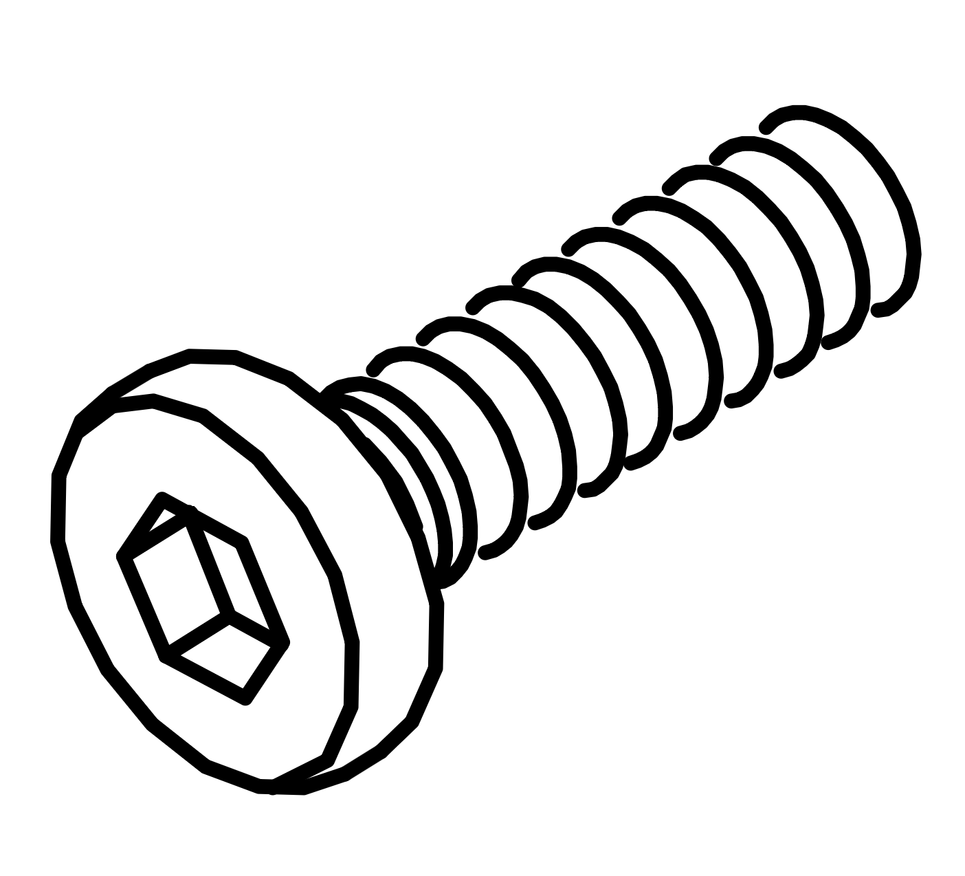
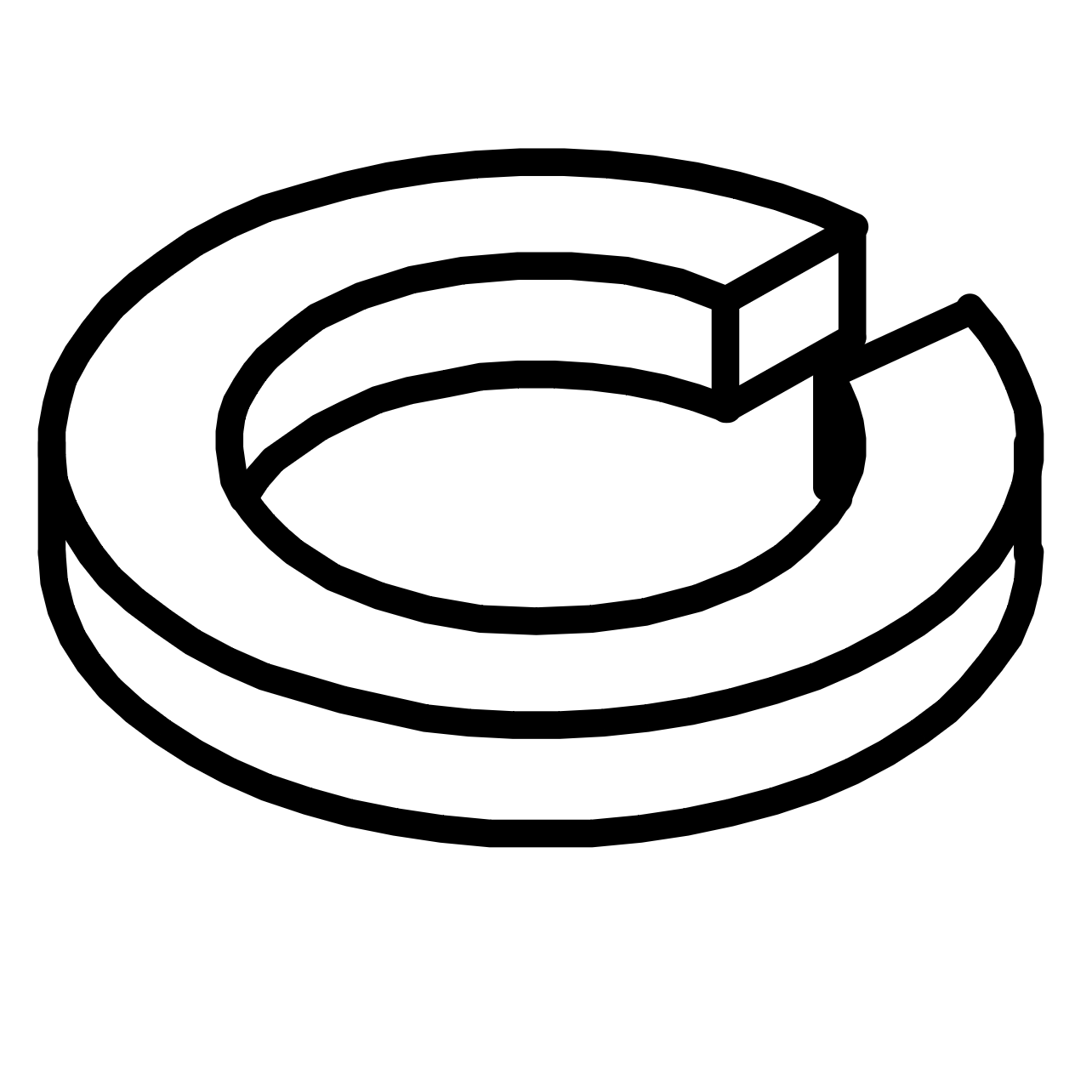
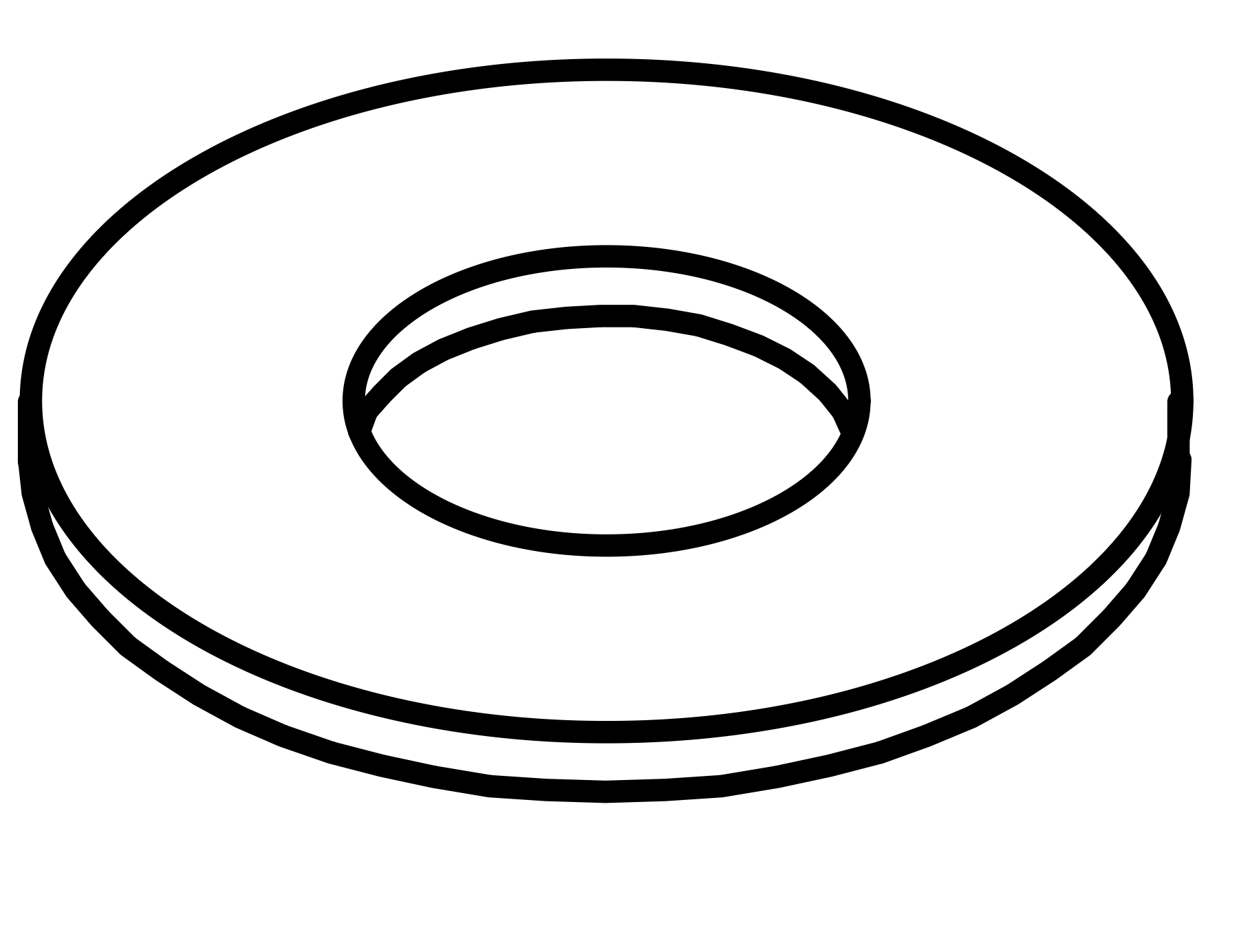
Attach the Leg Connection Brackets (17) to the Top Panel (2) and Stool Top Panel (6). For each bracket, use four Bolts (H), four Spring Washers (R), and four Flat Washers (S).
Ensure all arrows on the label point inward as shown in the diagram.
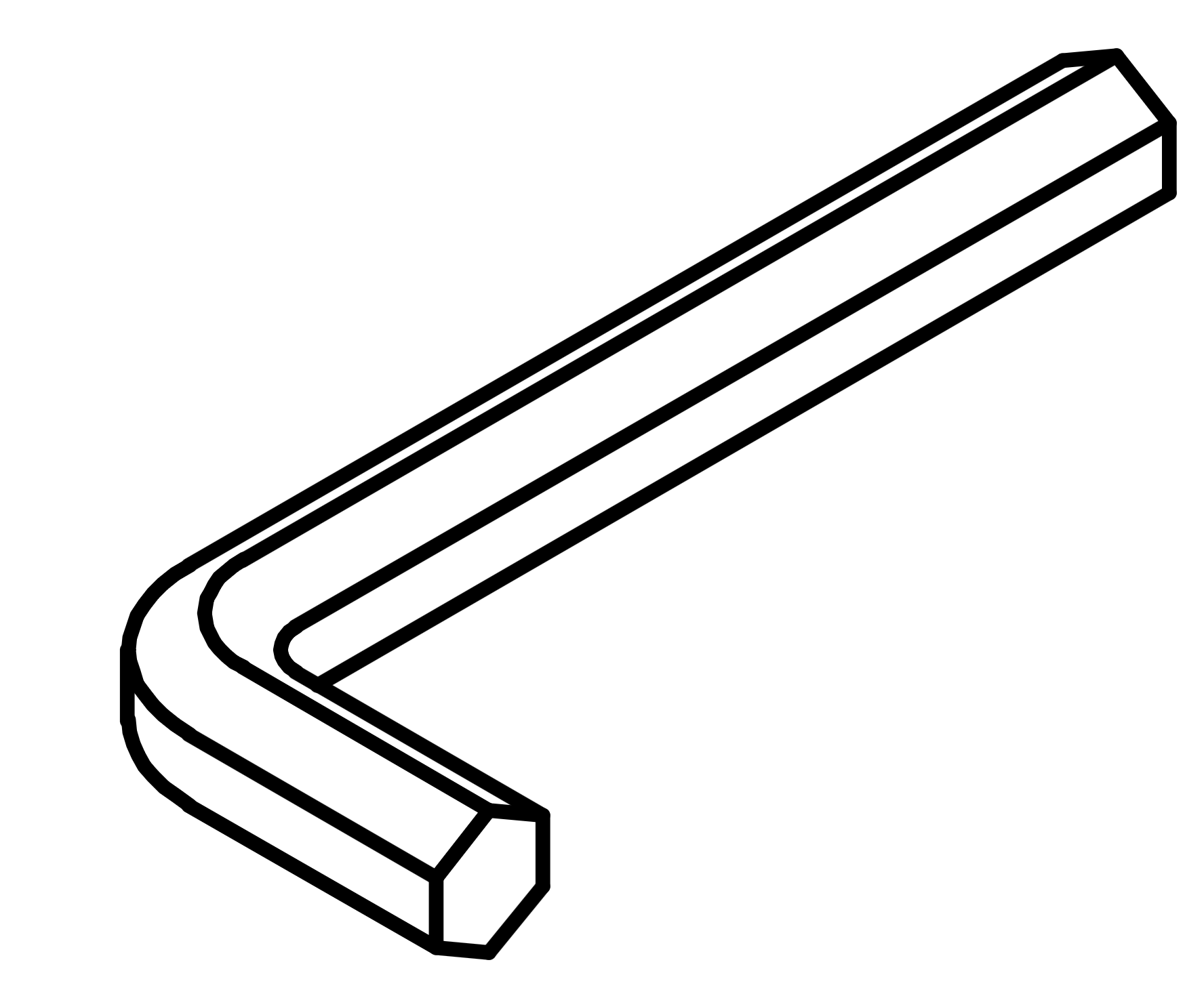
Tighten the bolts using the Allen Key (M). Repeat this process for all four brackets on each panel.
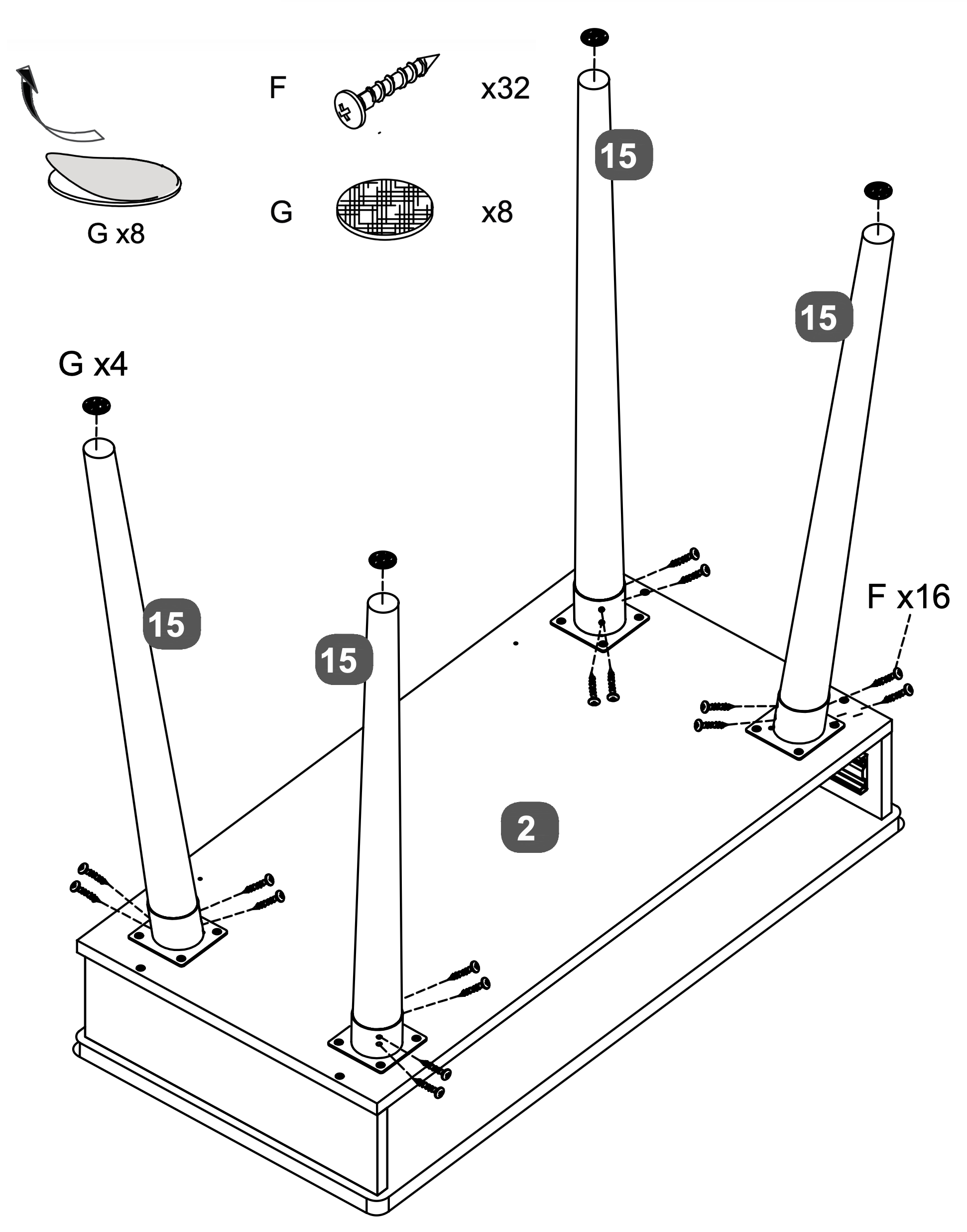
10. Leg Assembly and Stabilization
Attach the Table Legs (15) to the Top Panel (2) using sixteen Screws (F), four screws per leg. Ensure each leg is securely fastened.
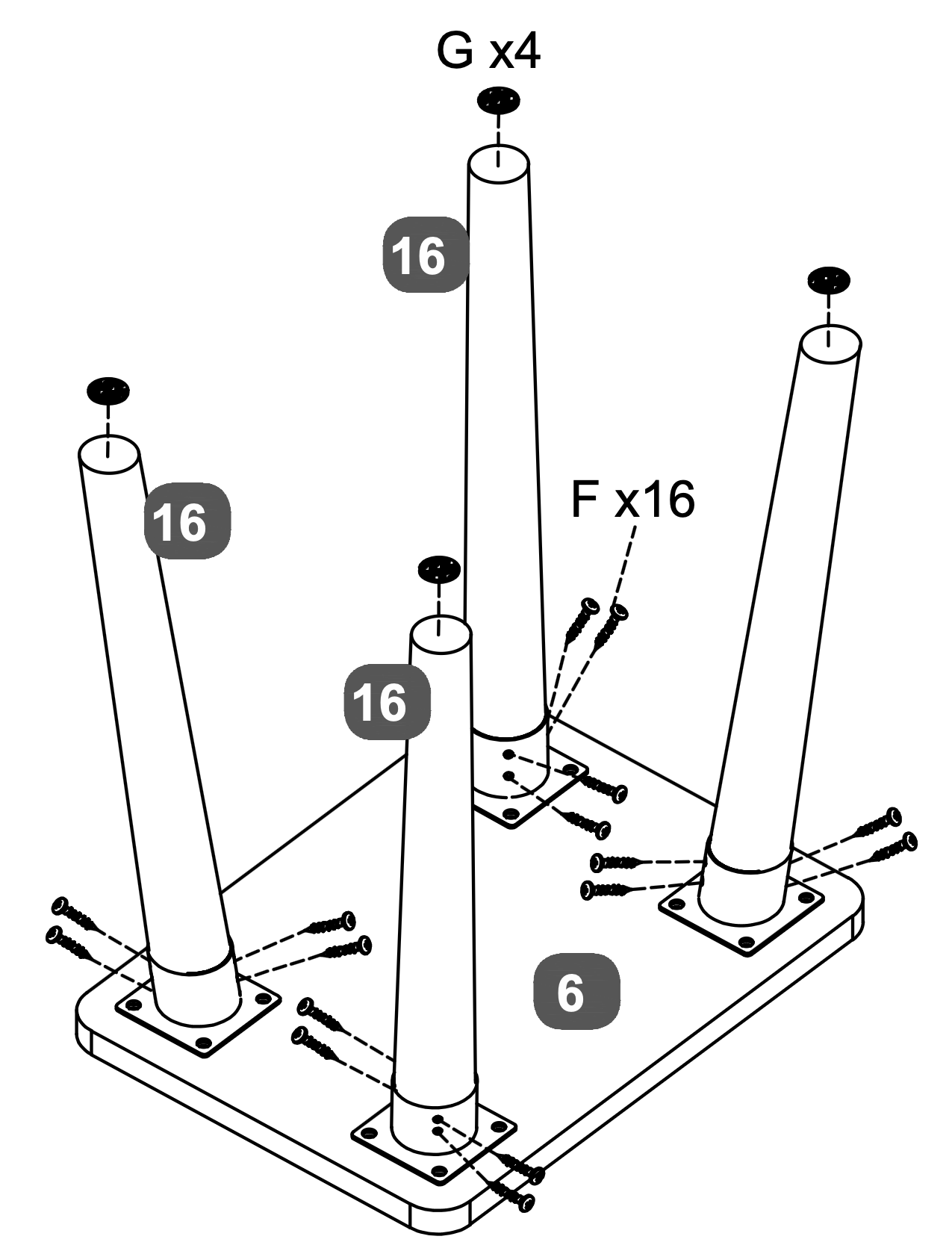
Attach the Stool Legs (16) to the Stool Top Panel (6) using another set of sixteen Screws (F), four screws per leg.
Apply the Pads (G) to the bottom of each leg for stability and protection. Use four pads for the table legs and four for the stool legs.
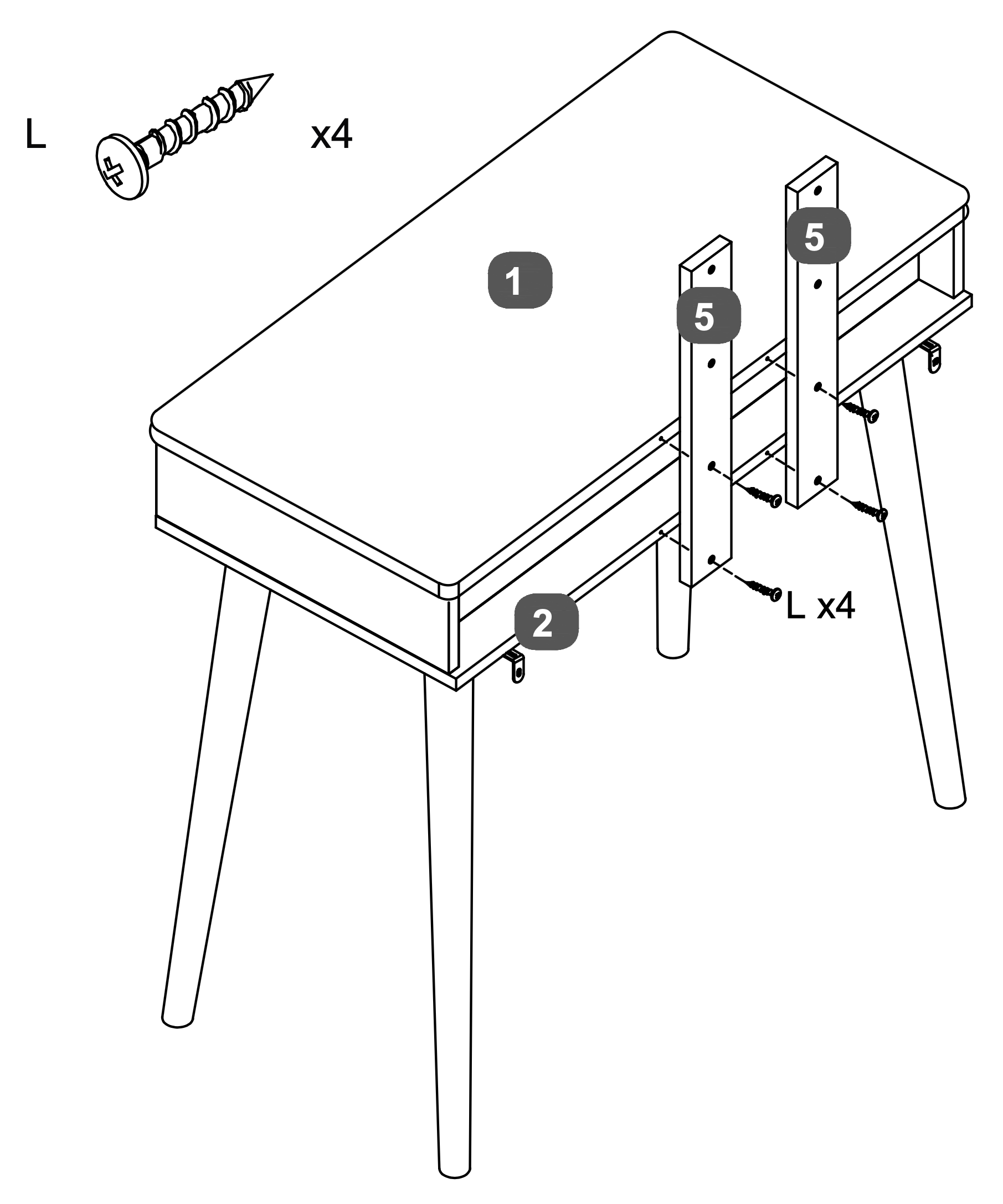
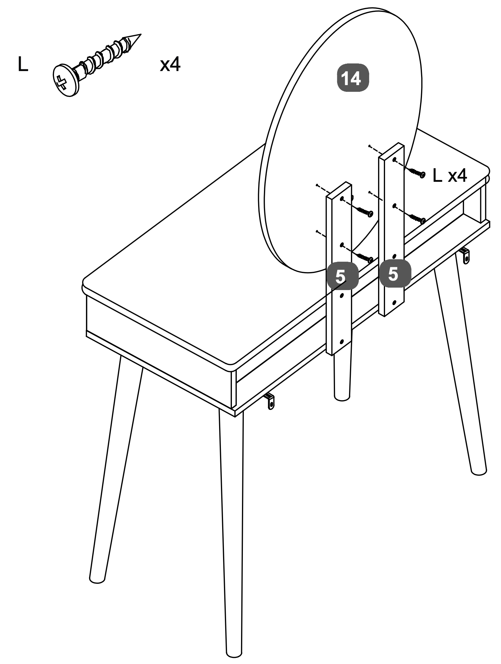
11. Rail Attachment and Alignment
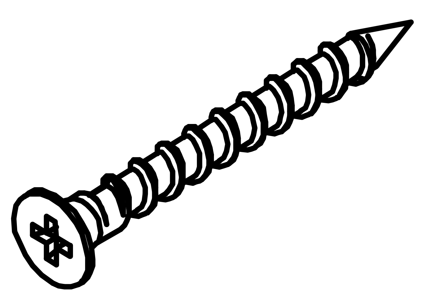
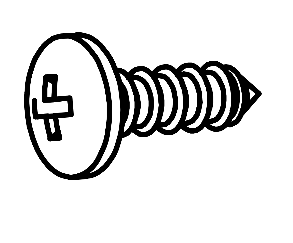
Warning: Please use the correct screw: (L) is 28mm long with a round head.
Attach the Mirror Support Rail (5) to the Top Panel (1) and Base Panel (2) using four Screws (L).
Ensure the rail is aligned correctly and securely fastened to the back of the table.
12. Mirror Attachment and Alignment
Warning: Please use the correct screw: (L) is 28mm long with a round head.
Attach the Oval LED Mirror (14) to the Mirror Support Rails (5) using four Screws (L).
Ensure the mirror is aligned correctly and securely fastened to the support rails.
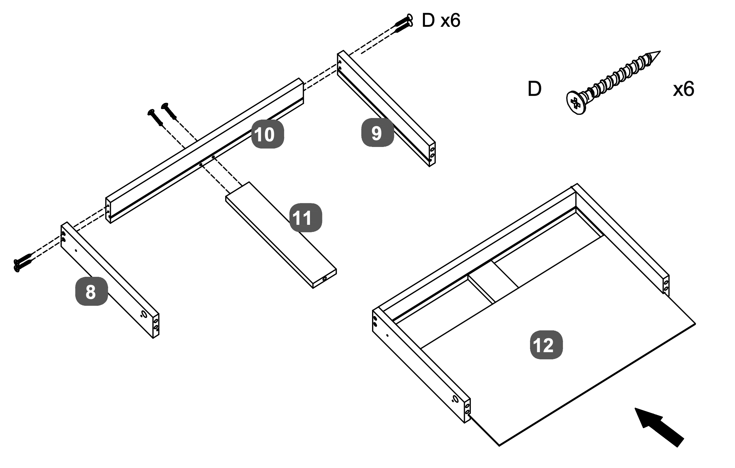
13. Drawer Assembly and Installation
Attach the LH Drawer Side (8) and RH Drawer Side (9) to the Drawer Back Panel (10) using Screws (D), two screws per side.
Insert the Drawer Base Support Rail (11) into the grooves of the assembled frame and attach with two Screw (D).
Slide the assembled drawer into the Drawer Base Panel (12), ensuring it fits securely.
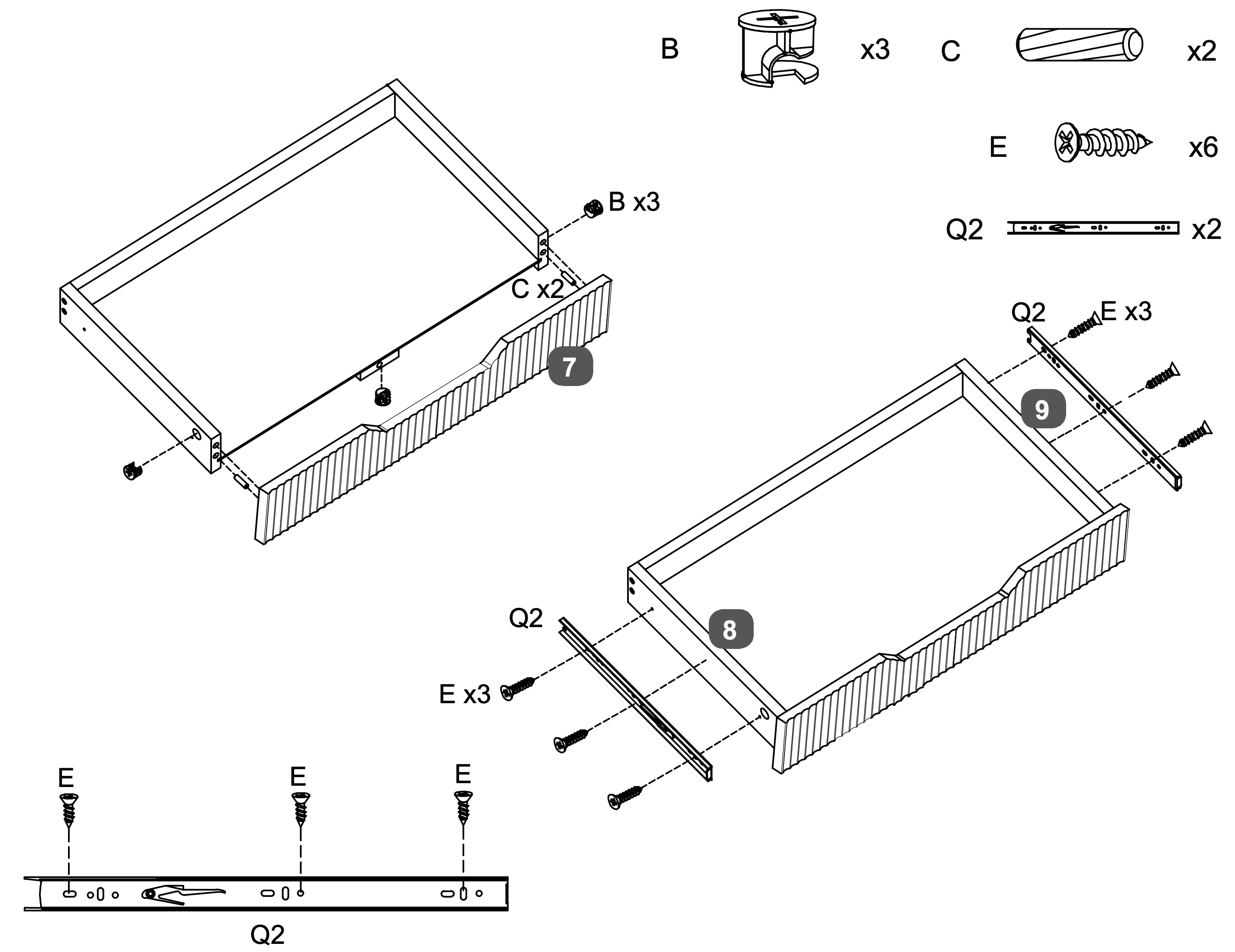
14. Drawer Frame Assembly and Alignment
Attach the Drawer Facia Panel (7) to the assembled drawer frame using three Cam Locks (B) and two Dowels (C). Ensure the panel is aligned correctly.
Secure the LH Drawer Side (8) and RH Drawer Side (9) to the Drawer Facia Panel (7) using six Screws (E), three screws per side.
Attach the Runners (Q2) to the sides of the drawer using three Screws (E) per runner, ensuring they are aligned properly for smooth operation.
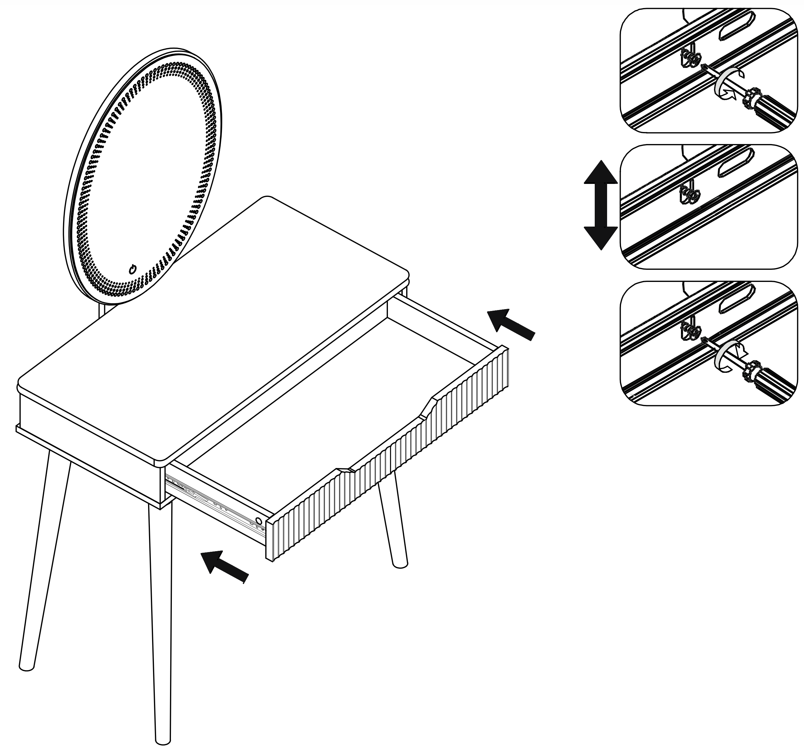
15. Drawer Installation and Adjustment
Insert the assembled drawer into the dressing table by aligning the Runners (Q2) on the drawer with the corresponding tracks inside the table.
Ensure the runners are correctly positioned and slide the drawer in until it fits securely.
Adjust the runners as needed to ensure smooth operation.
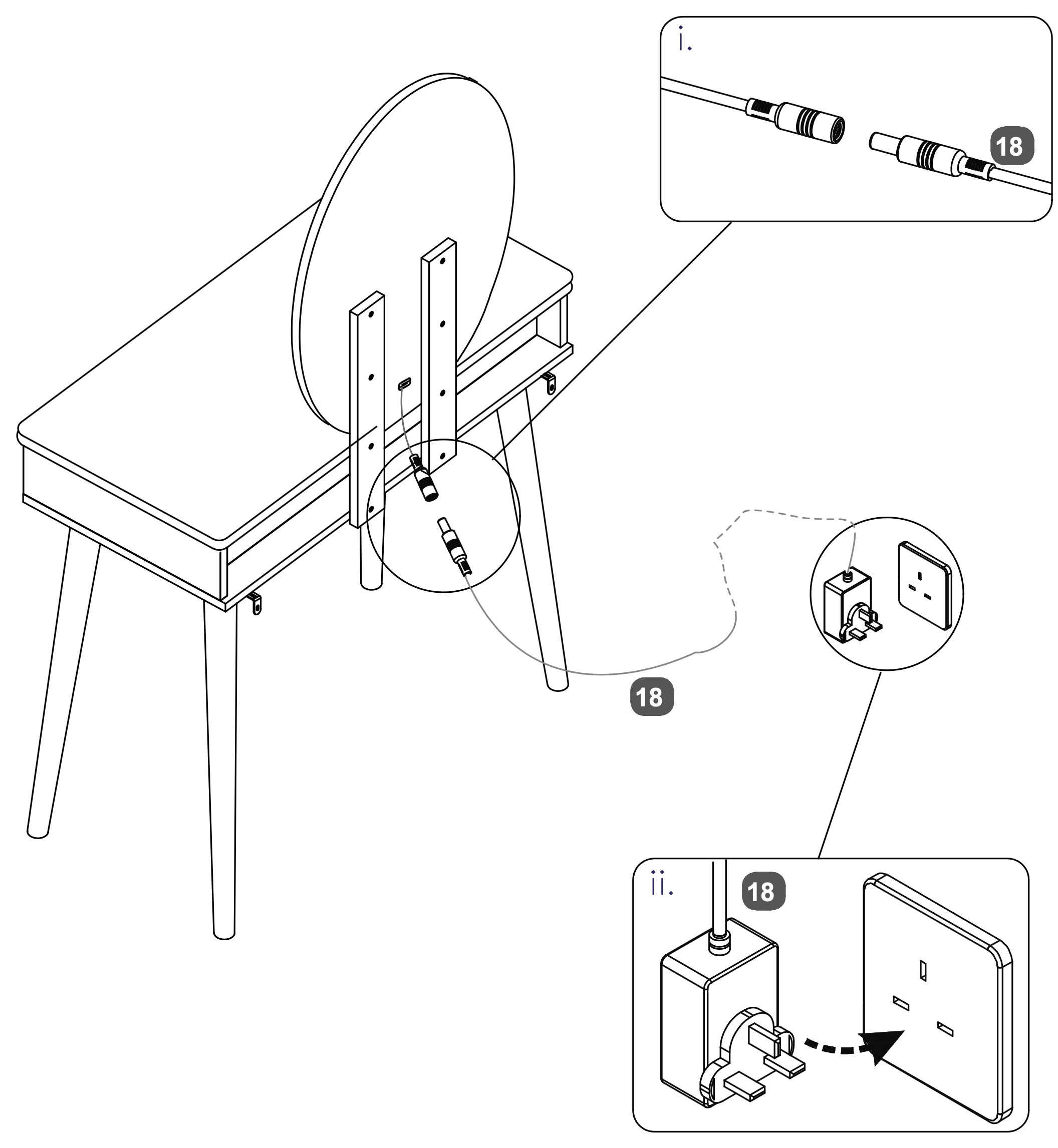
16. Power Connection Setup
Connect the Power Supply Adapter (18) to the socket on the back of the Oval LED Mirror (14). Ensure the connection is secure.
Plug the other end of the Power Supply Adapter (18) into a wall outlet to power the LED mirror.
Please plug into your wall socket first, then into the mirror.
The mains power supply must be earthed.
If the Power Supply Adapter is changed for any reason, please use one with the same rating - 5V 2A (10W).
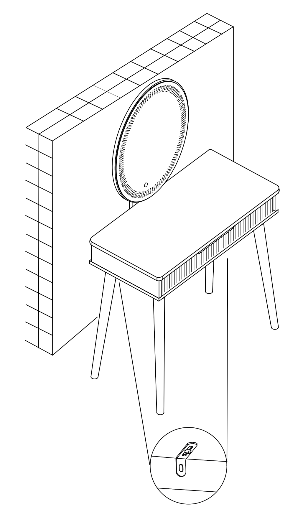
17.
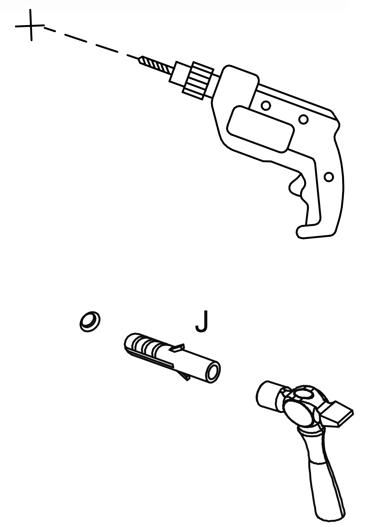
Warning: Always ensure the area to be drilled is free from hidden electrical wires, water and gas pipes.
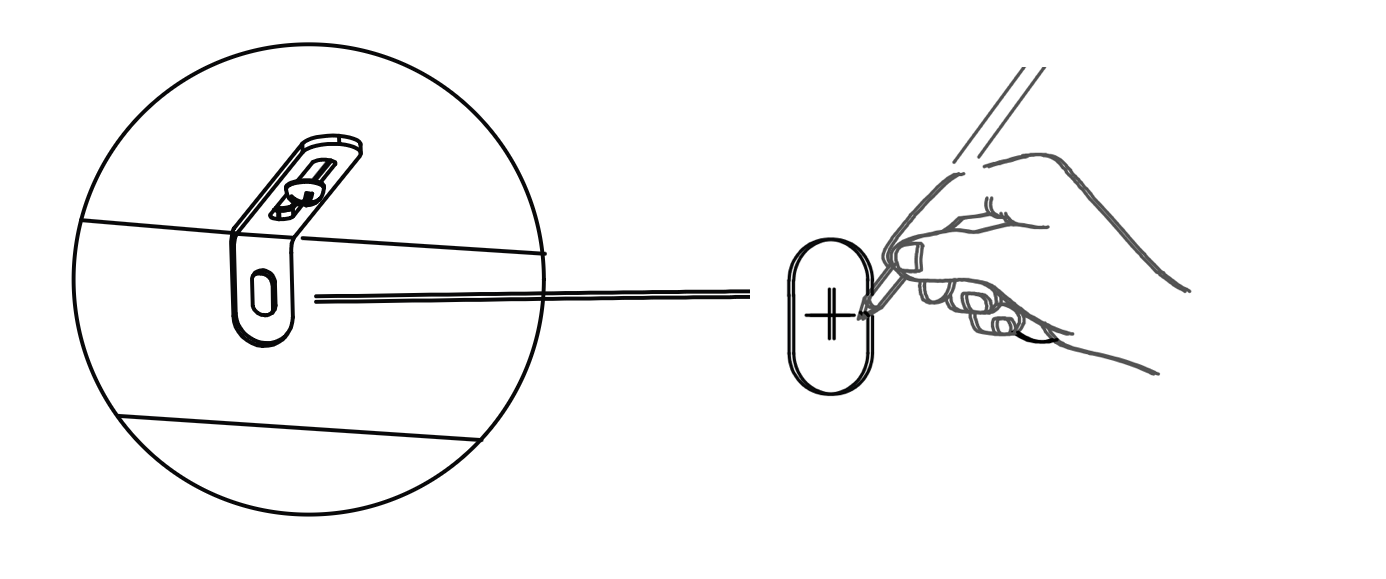
Place the table in the position in which it will be used, flat against a wall. (I)
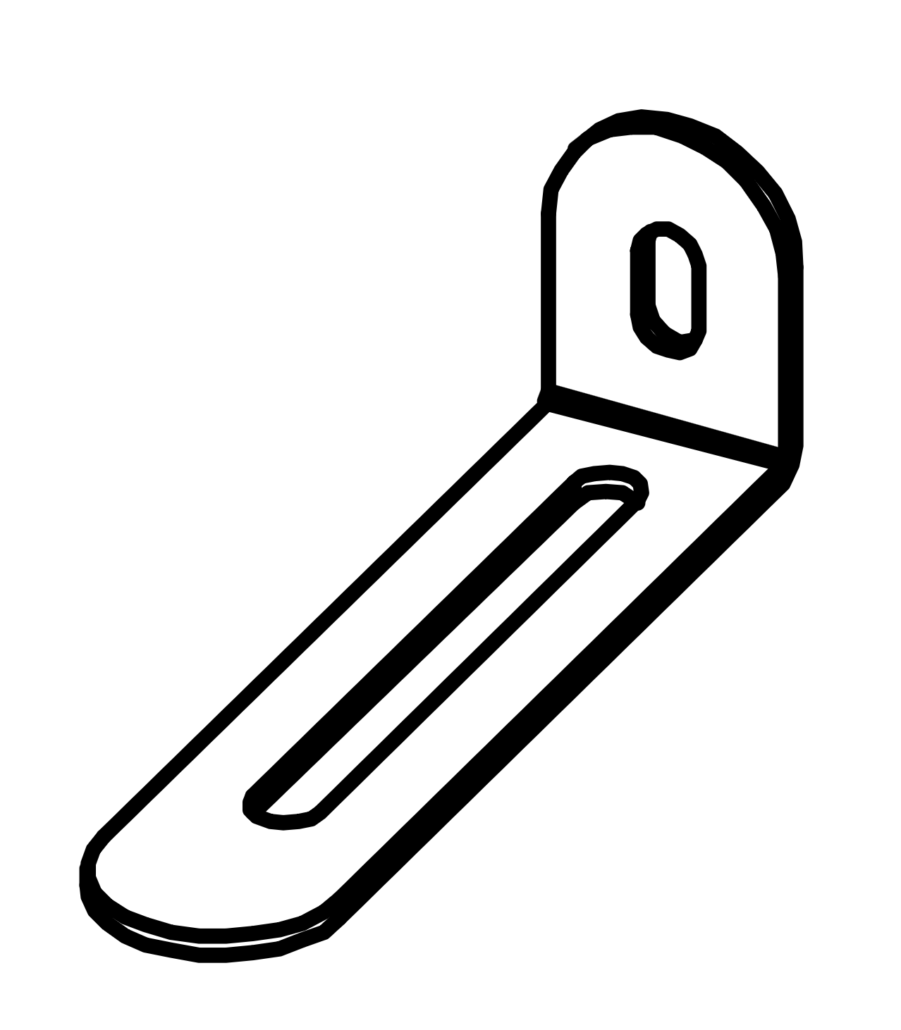
From the underside of the base panel (2) carefully mark the wall with a sharp pencil, dead-centre of the holes in the short leg of the Metal Anti-tilt Bracket.
Carefully drill holes through the marks into the wall.
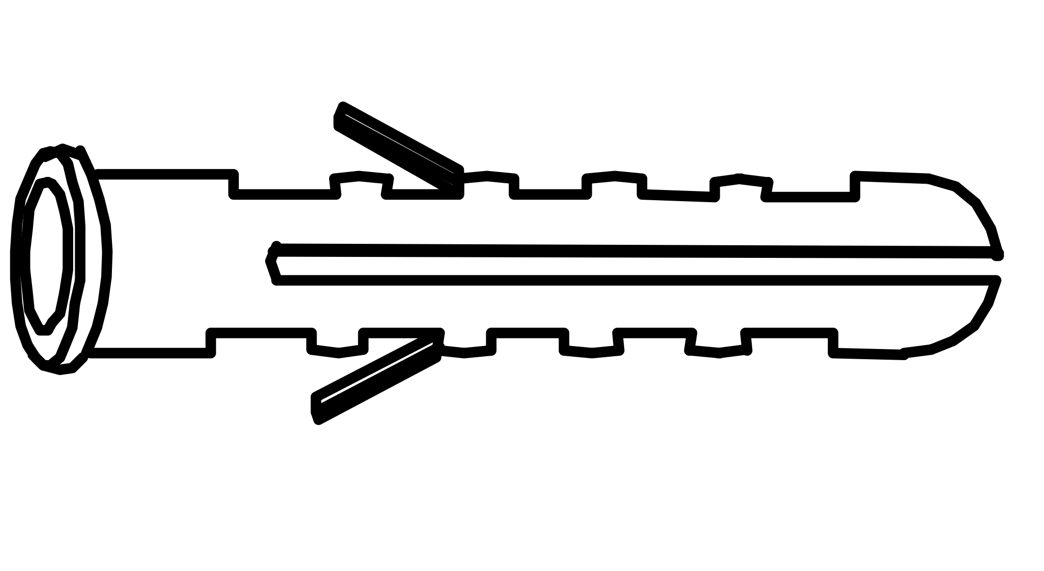
If the wall is suitable, tap in the wall plug provided. If it isn't, use an appropriate fixing.
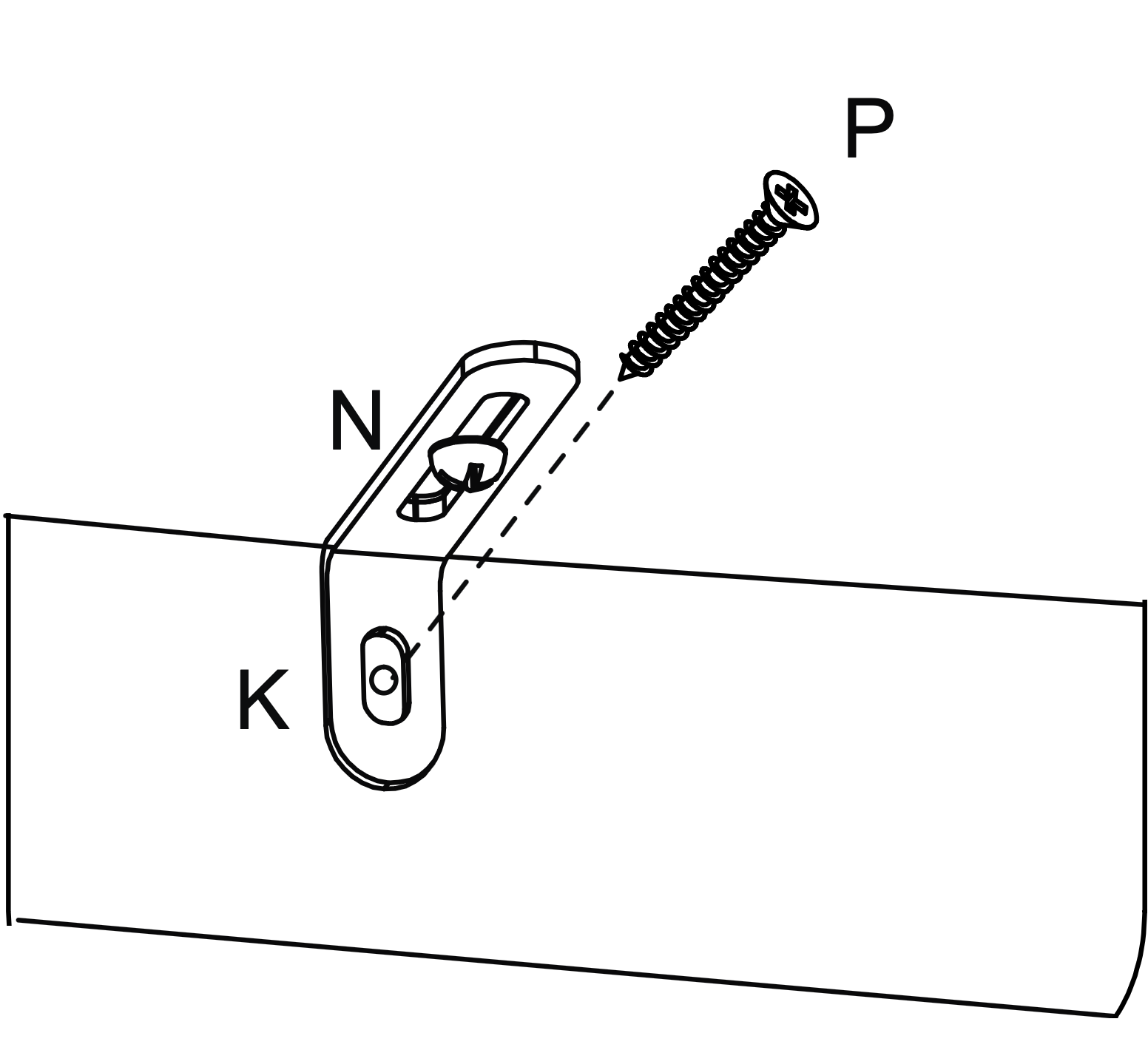
Hold the table firmly against the wall.
If necessary loosen screw (N) a little and push the short leg of the metal bracket (K) firmly against the wall.
Screw into the wall fixings making sure brackets are firm, finally retighten screws (N).