Assembly instructions for Ravello Stone Ottoman TV Bed Frame by Time4Sleep
Product Information
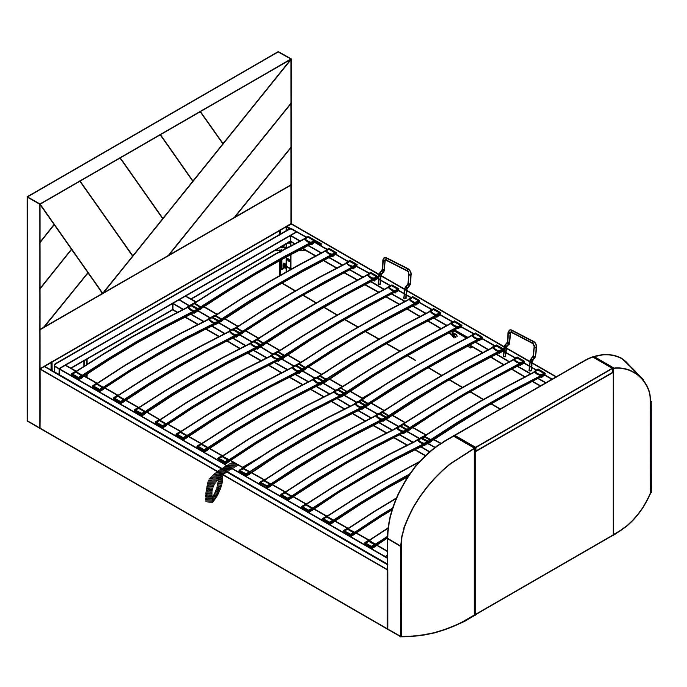
Ravello Stone Ottoman TV Bed Frame
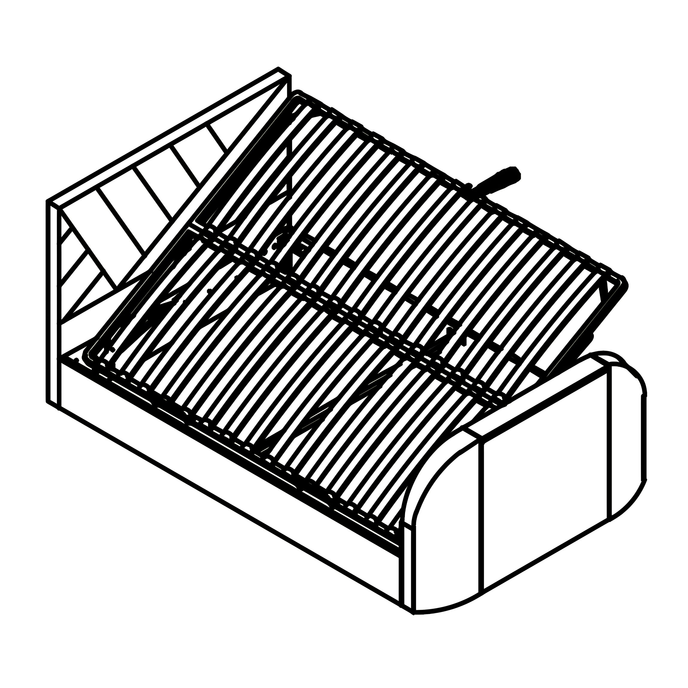
The Ravello Ottoman Bed is a stylish and practical choice for modern bedrooms. Featuring a tall headboard and upholstered finish, it creates a striking centrepiece while offering discreet under-bed storage. The gas-lift mechanism smoothly raises the slatted base to reveal a generous 25cm-deep compartment, ideal for keeping bedding, clothes, or seasonal items neatly stored away. Available in Double and King sizes, the Ravello combines comfort, durability, and space-saving design in one elegant frame.
SKU
RavottTV46Stone,RavottTV50Stone
Double
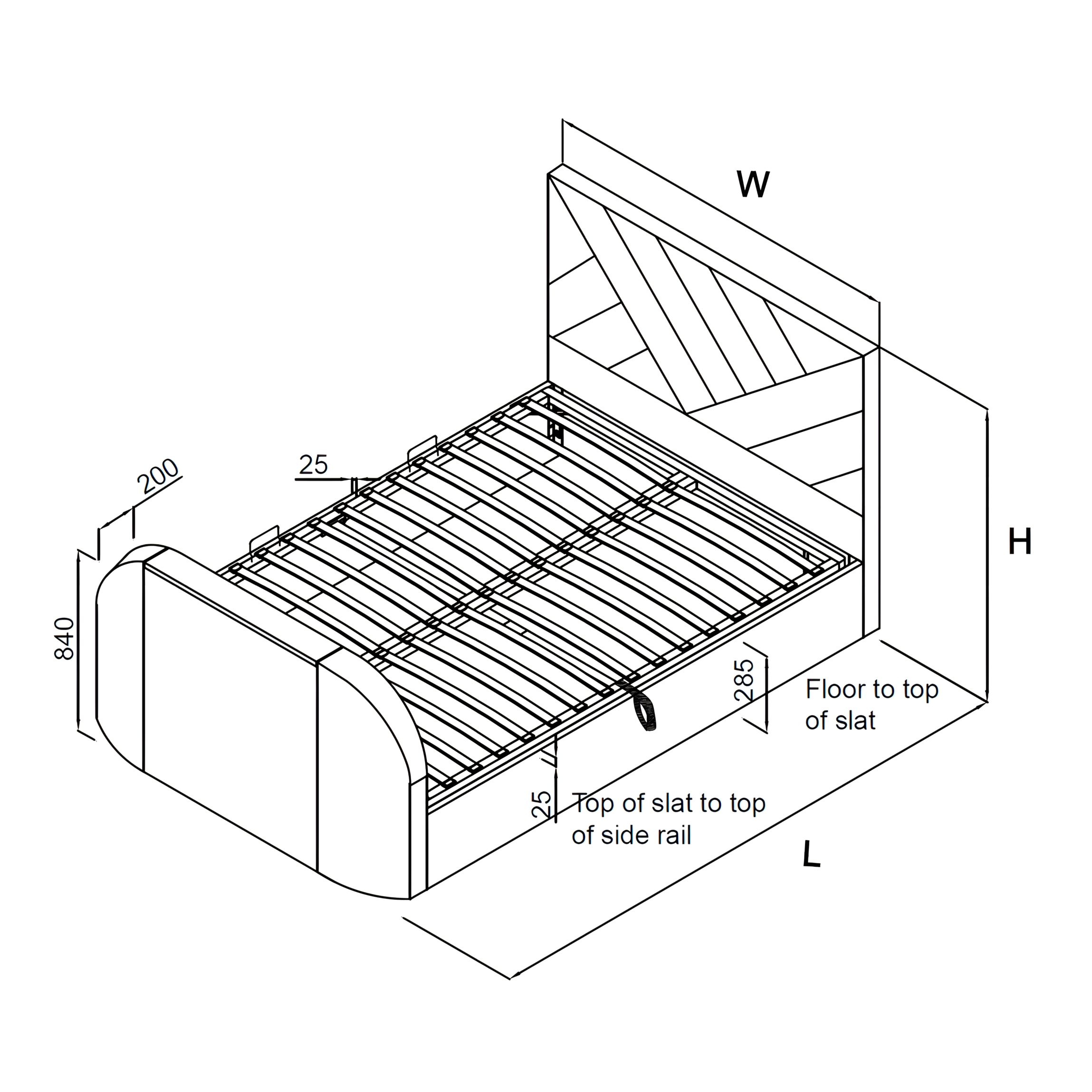
Overall Dimensions (LWH mm)
2215 x 1445 x 1200
Storage Dimensions (LWH mm)
1945 x 1370 x 250
Double King Overall Dimensions (LWH mm) 2215 x 1445 x 1200 2315 x 1595 x 1200 Storage Dimensions (LWH mm) 1945 x 1370 x 250 2045 x 1520 x 250 Distance between slats (mm)
70
Slat Dimension (mm)
670 x 53 x 9.5
Ottoman Piston Strength
800N
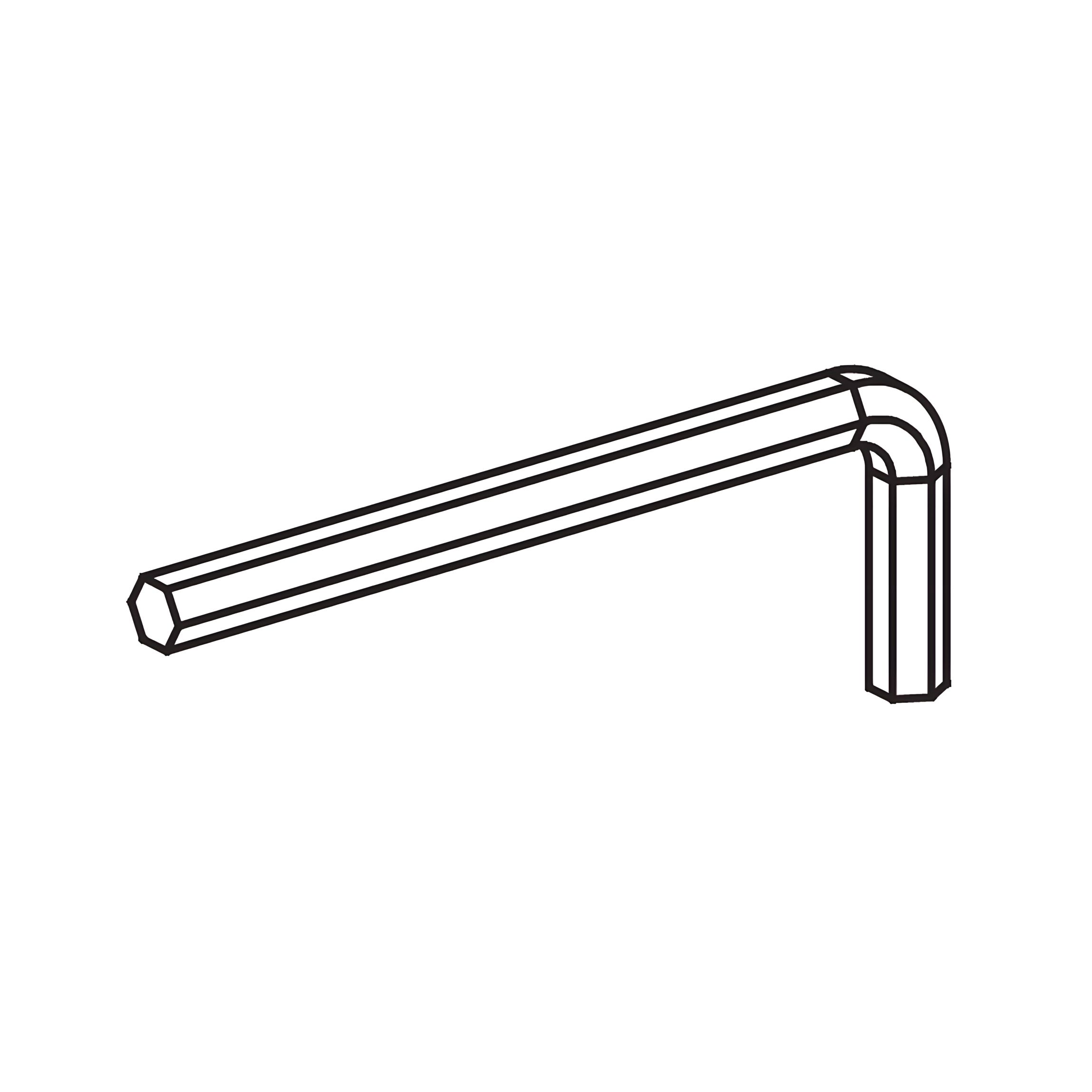
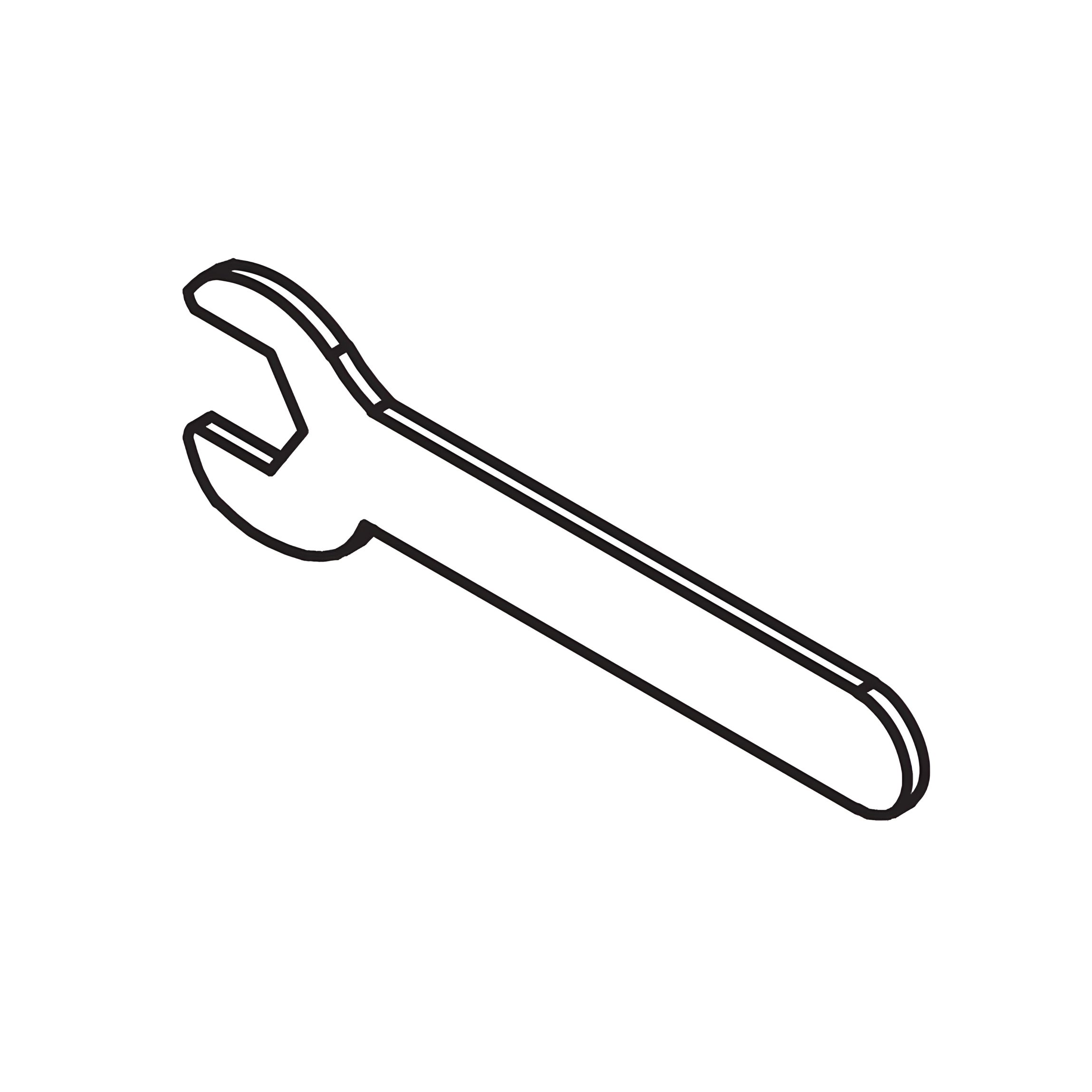
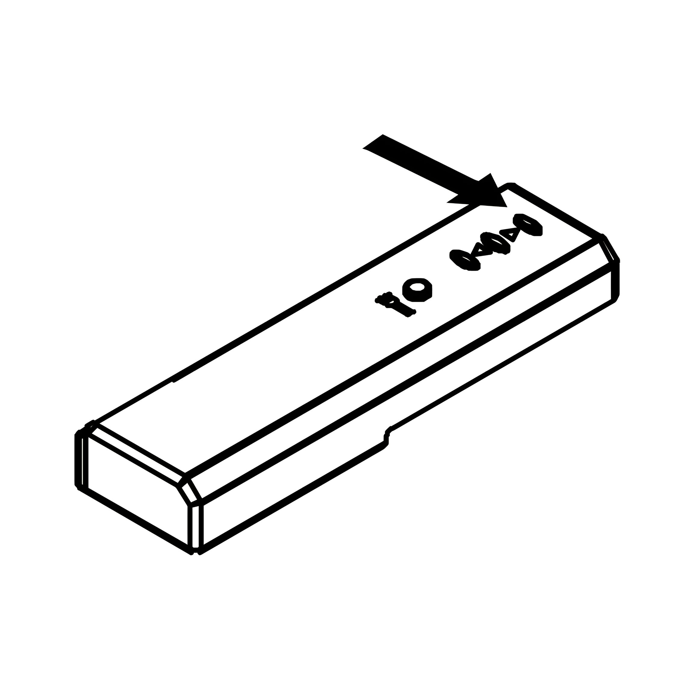
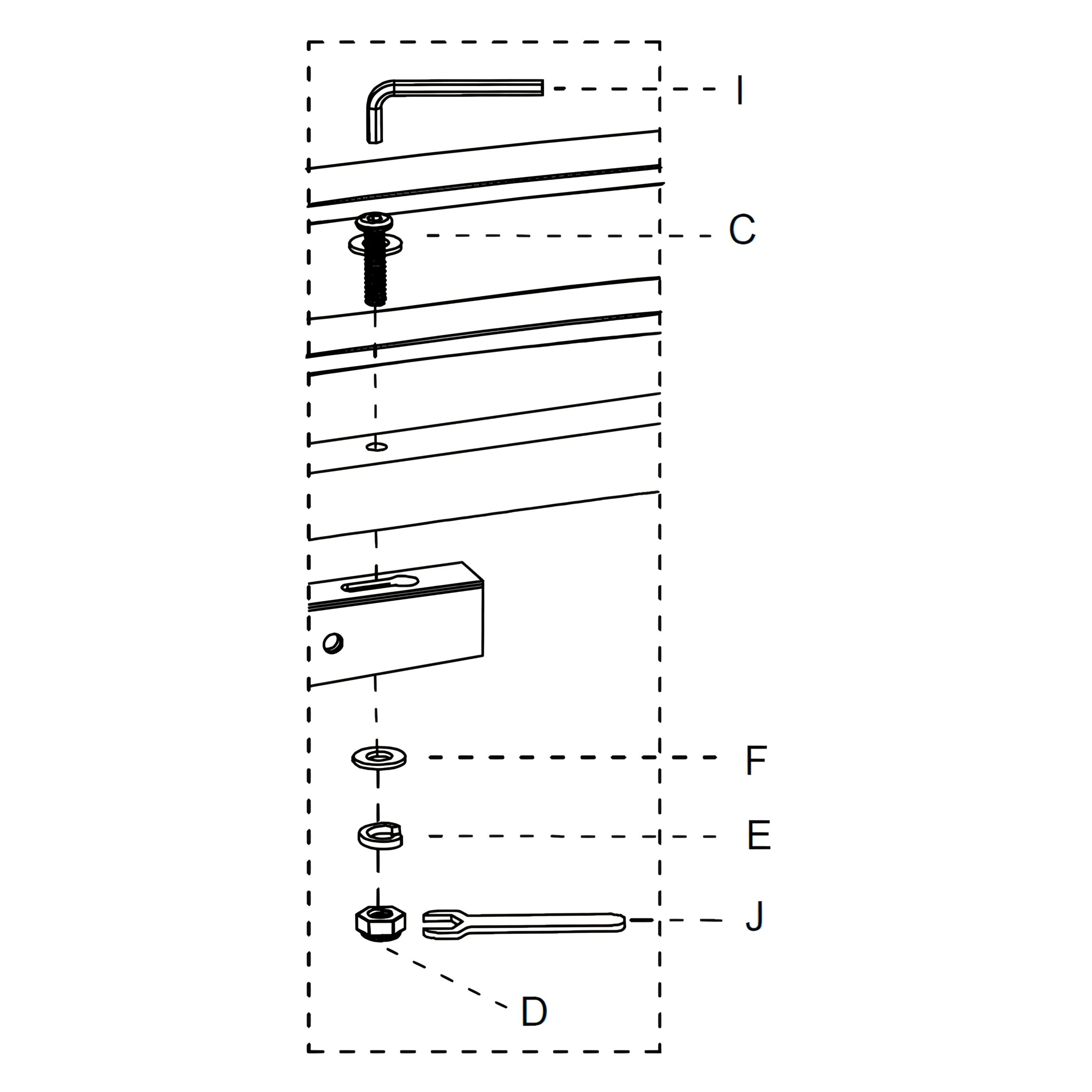
Tools
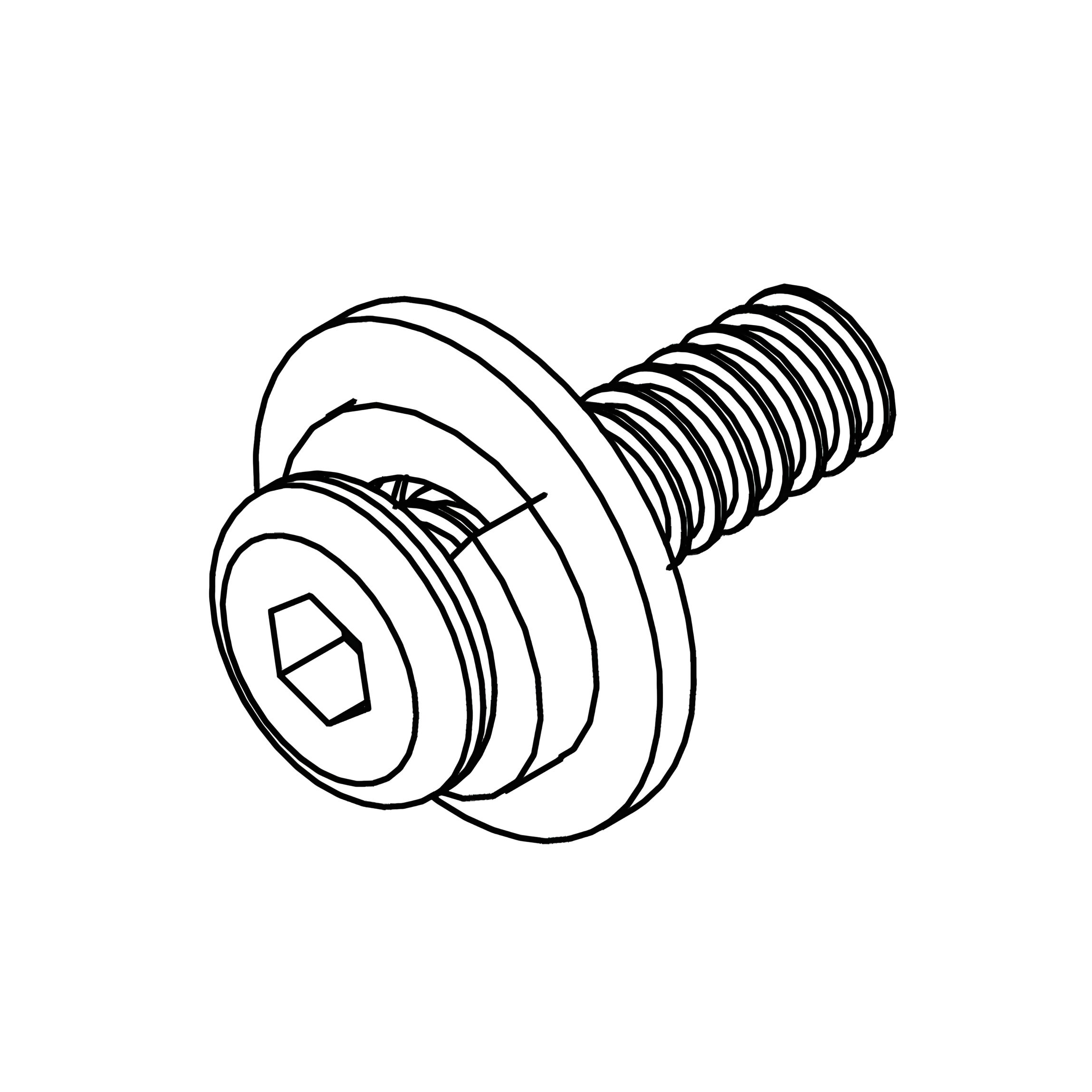
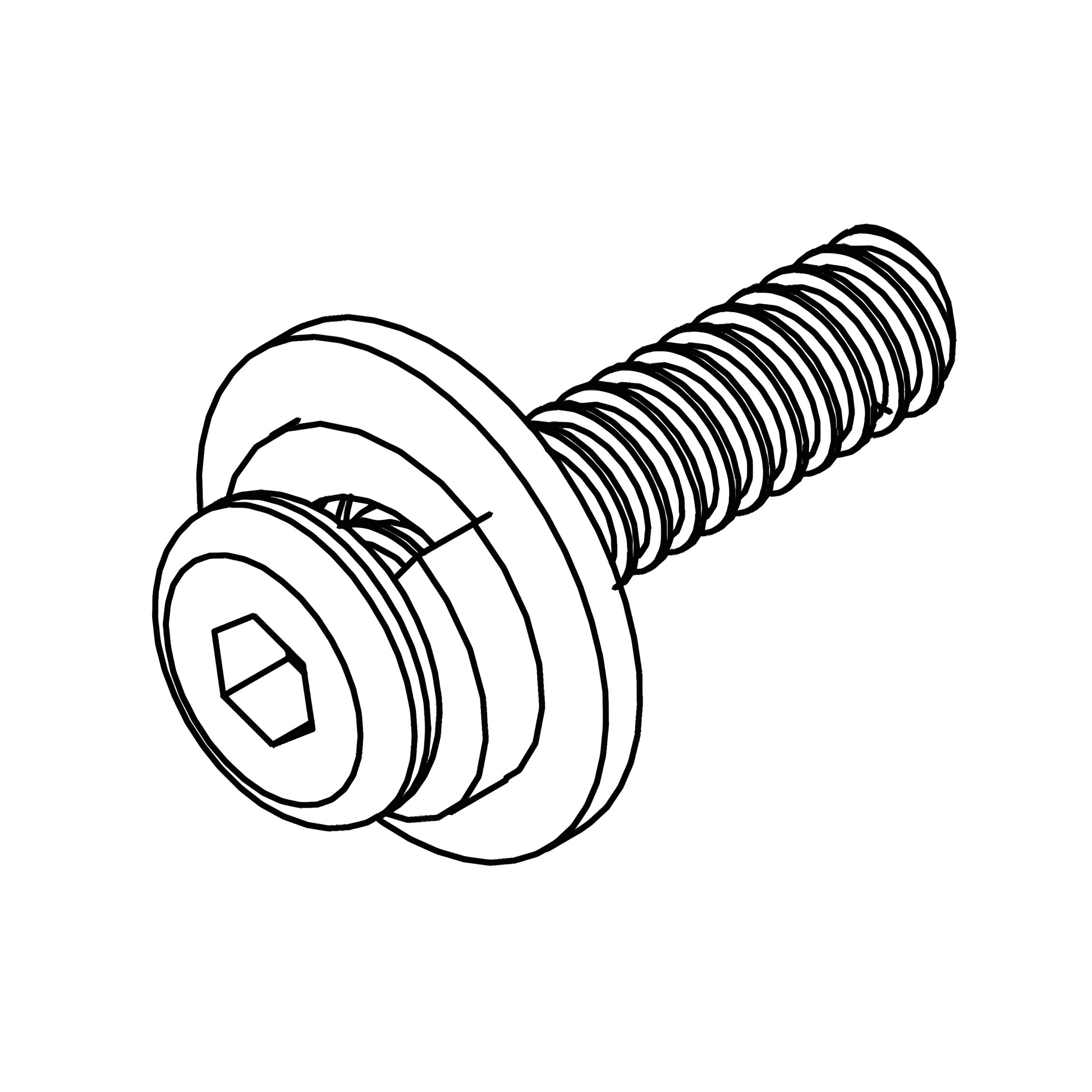
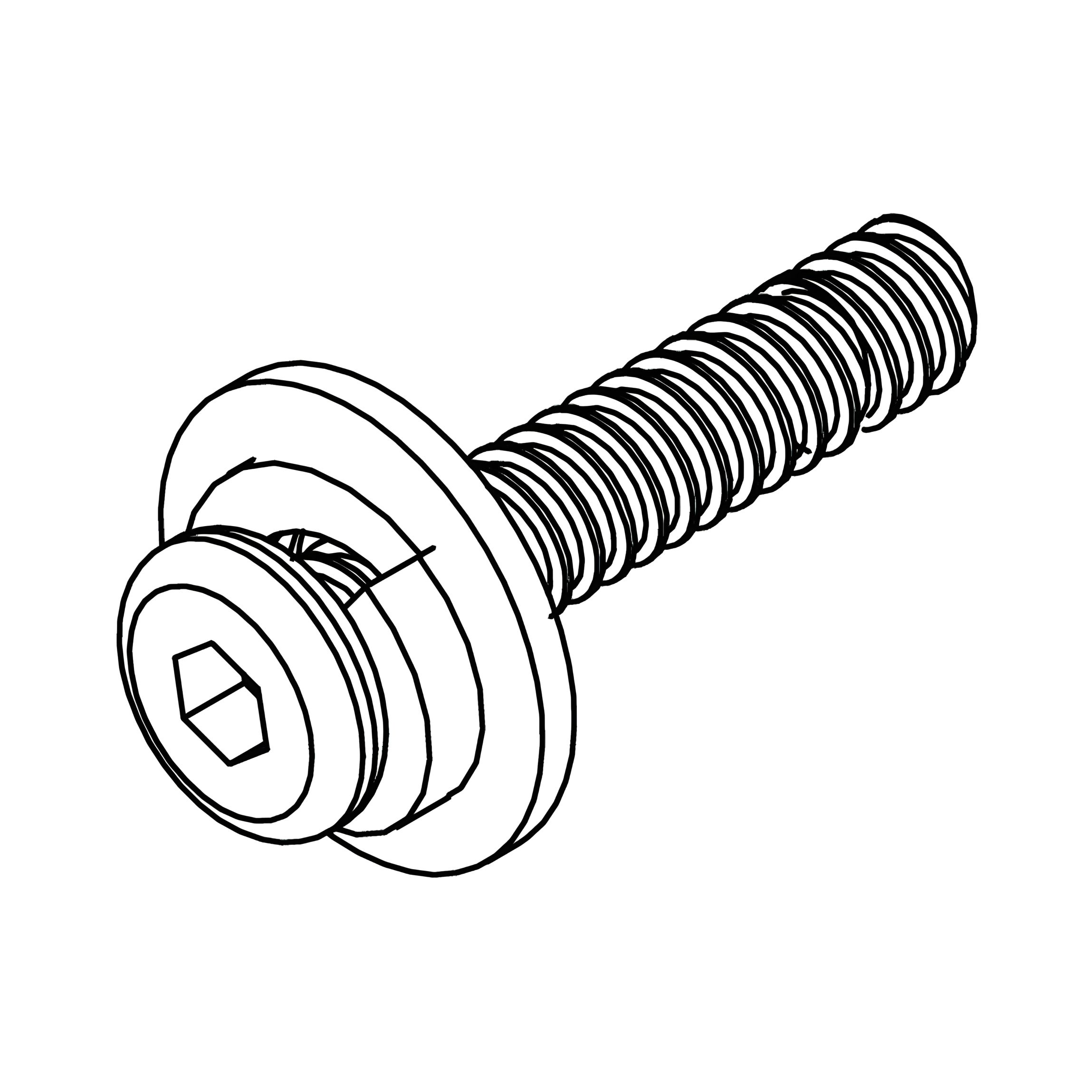
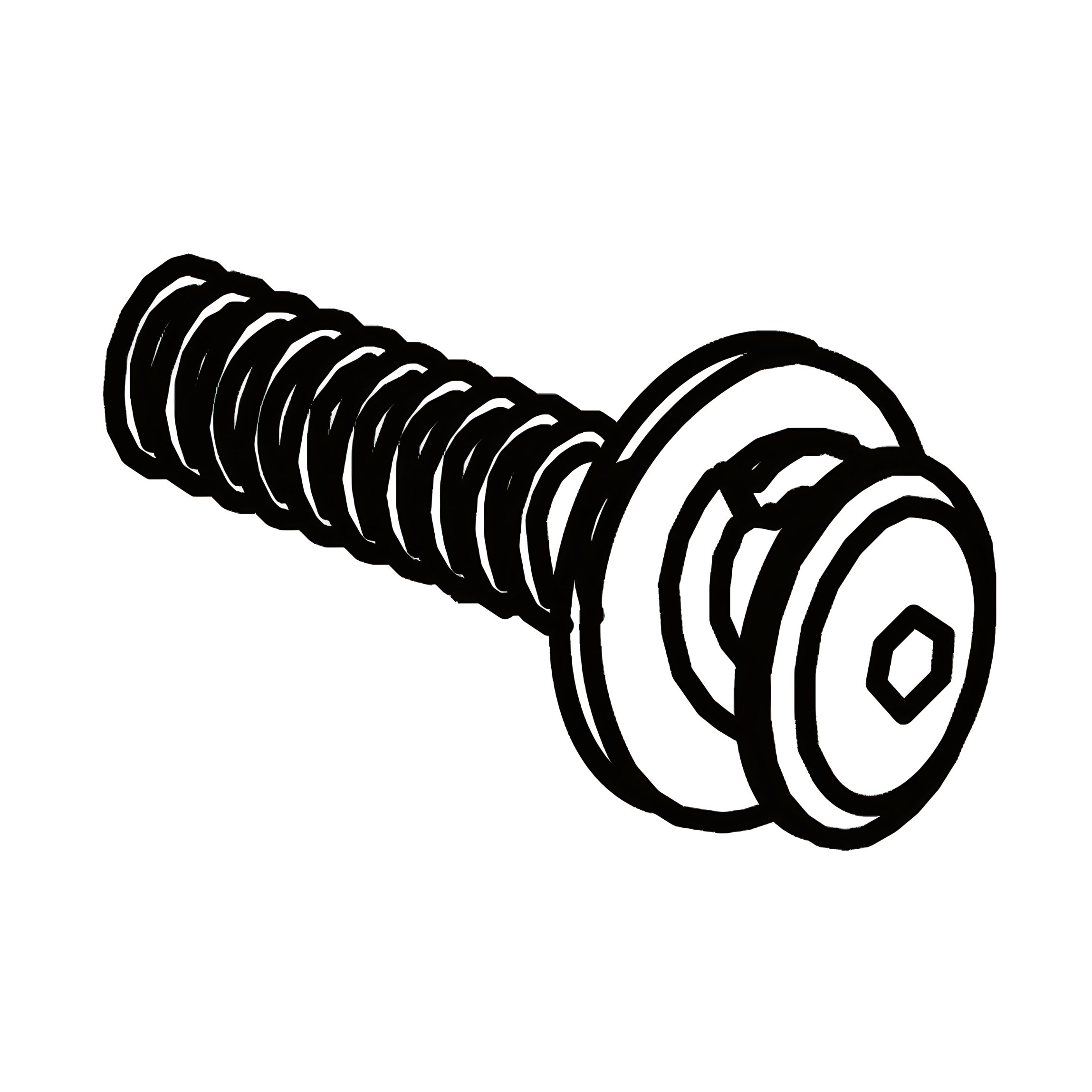
A - Bolt (M8x25mm)
B - Bolt (M8x35mm)
C - Bolt (M8x50mm)
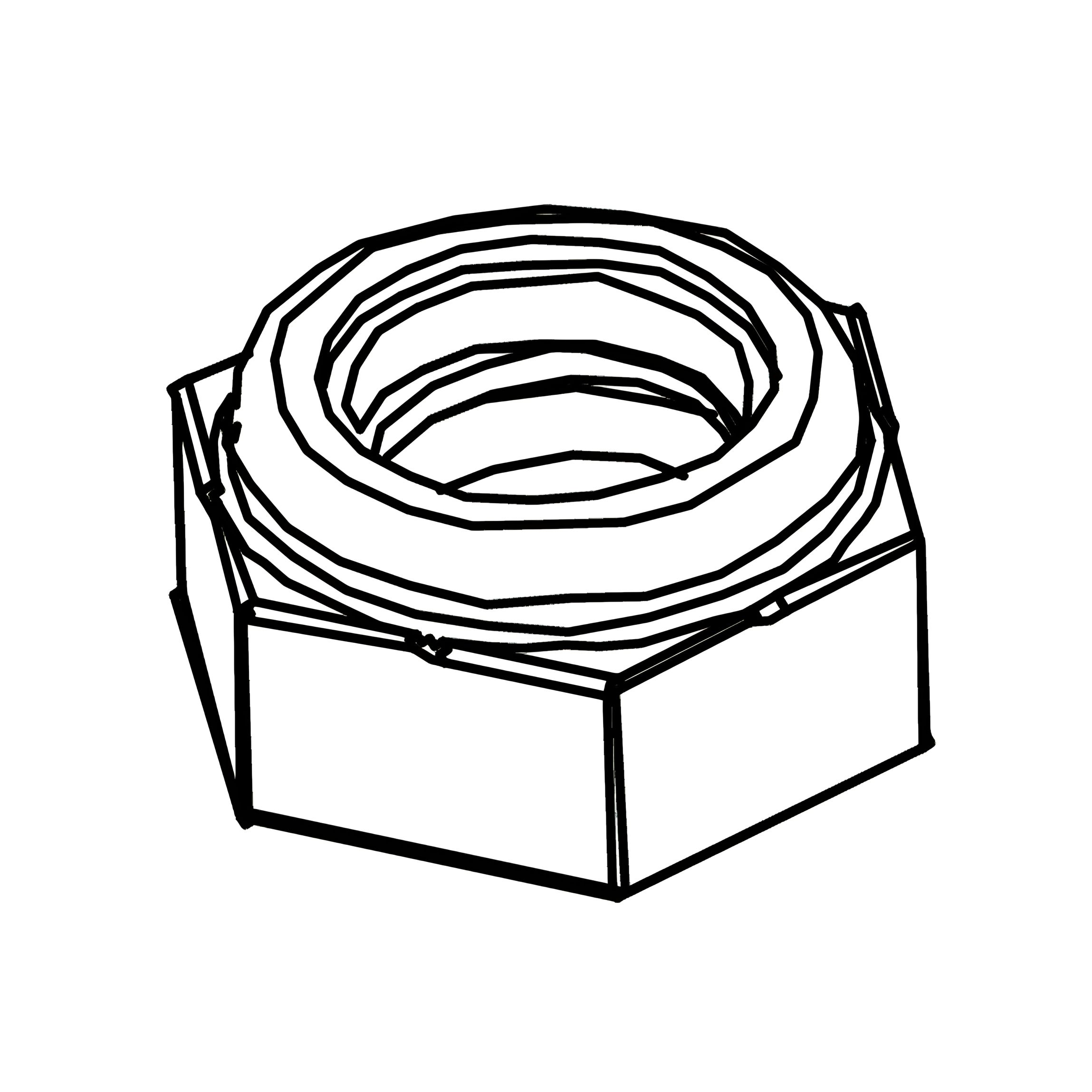
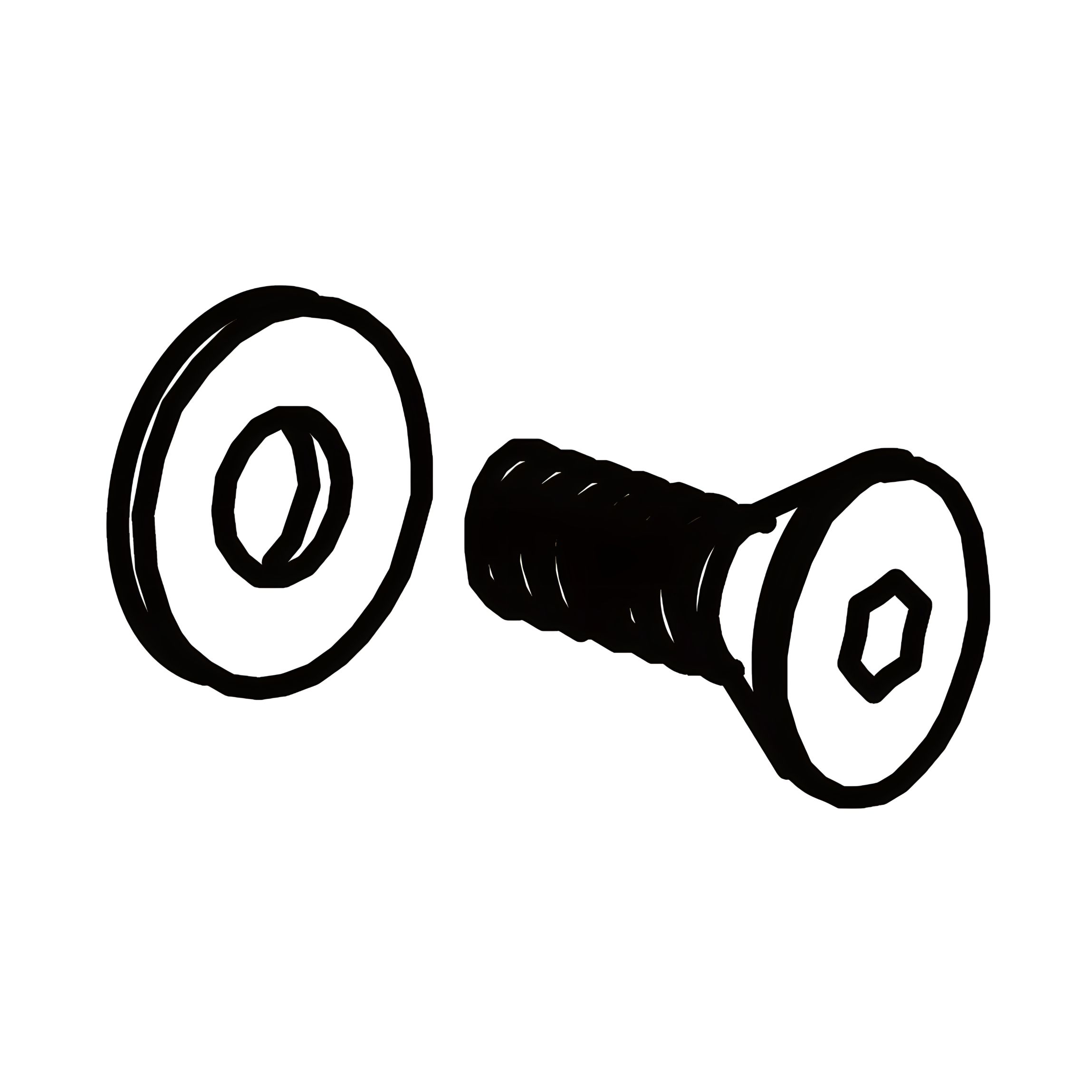
D - Flanged Lock-Nut M8
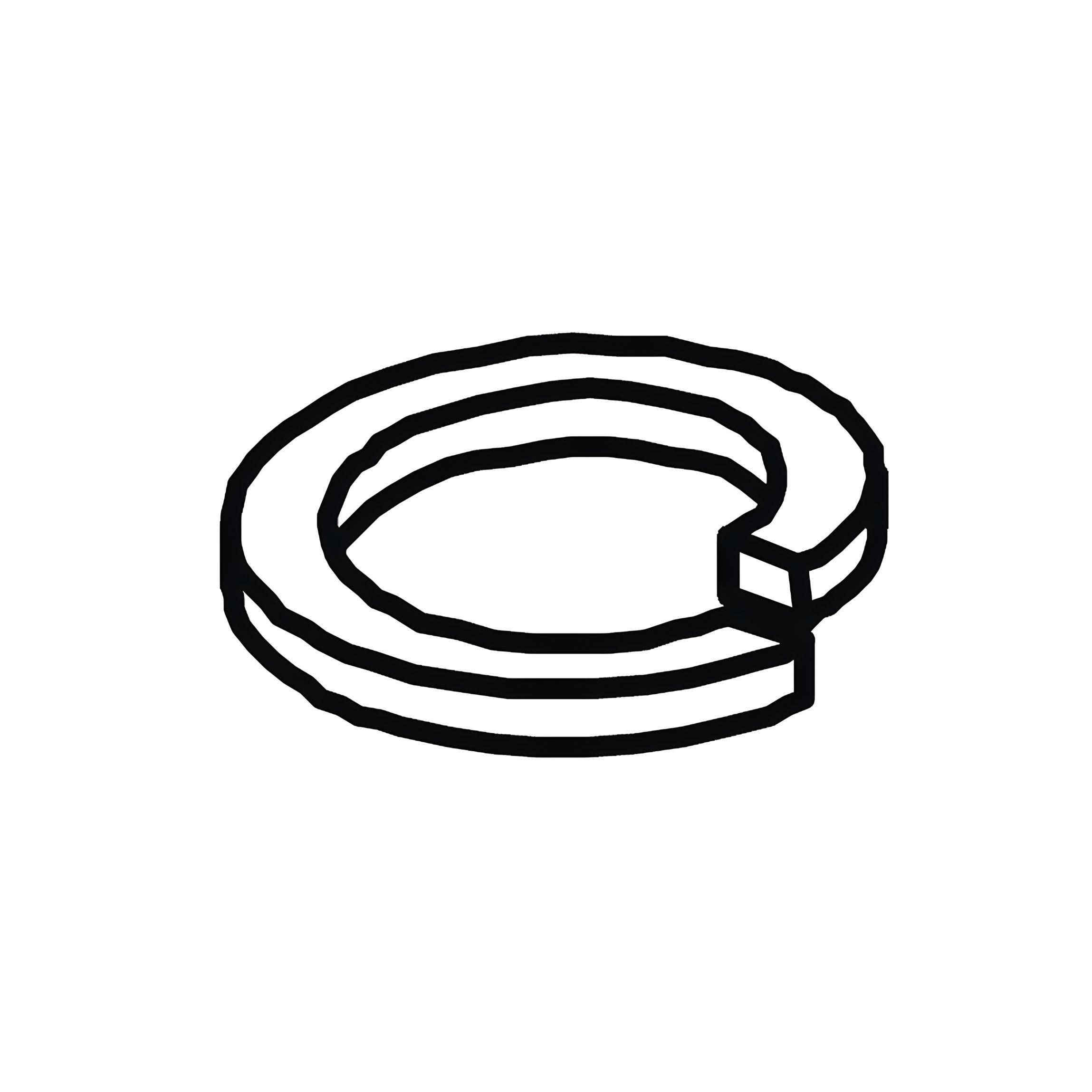
E - Spring Washer For M8 Bolts
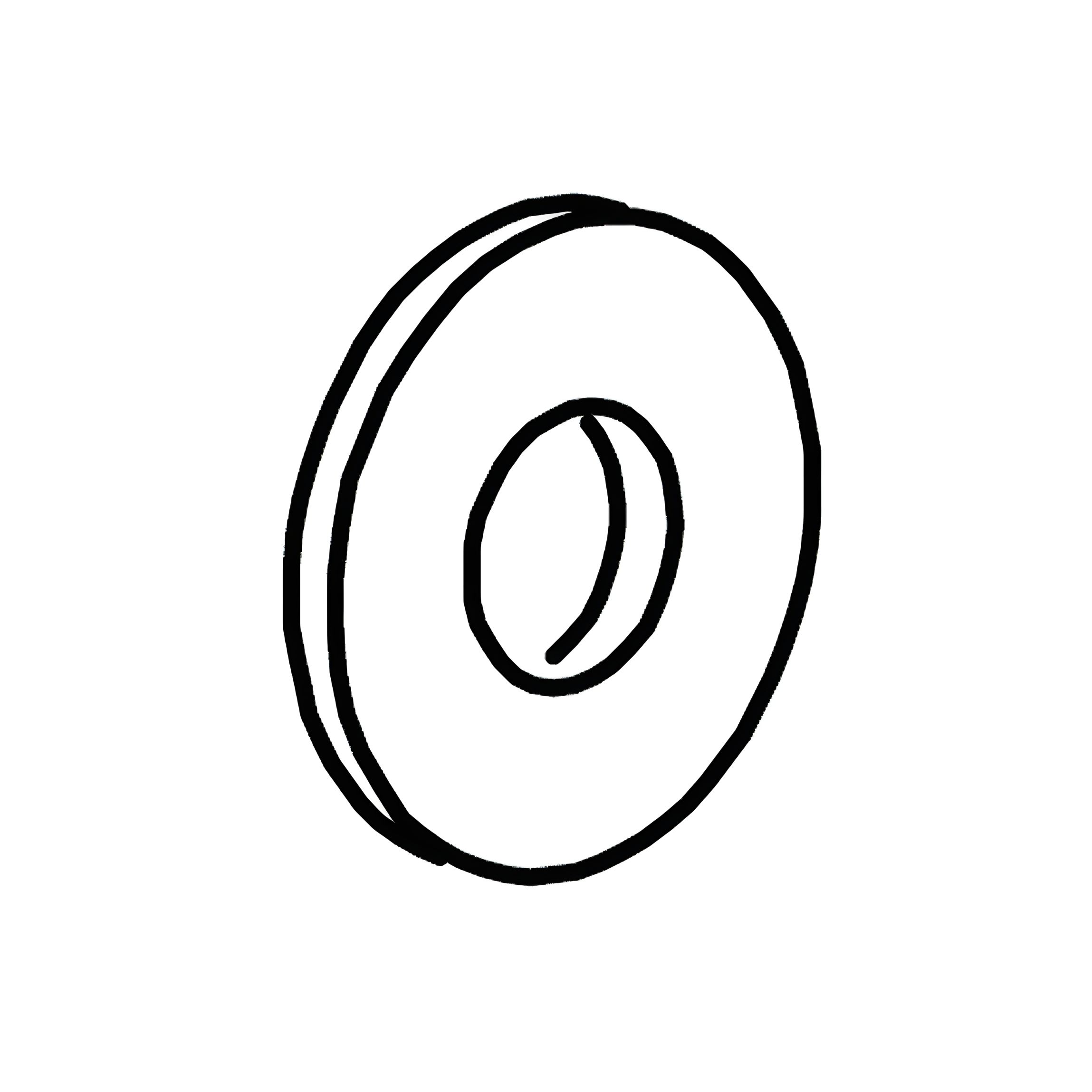
F - Flat Washer For M8 Bolts
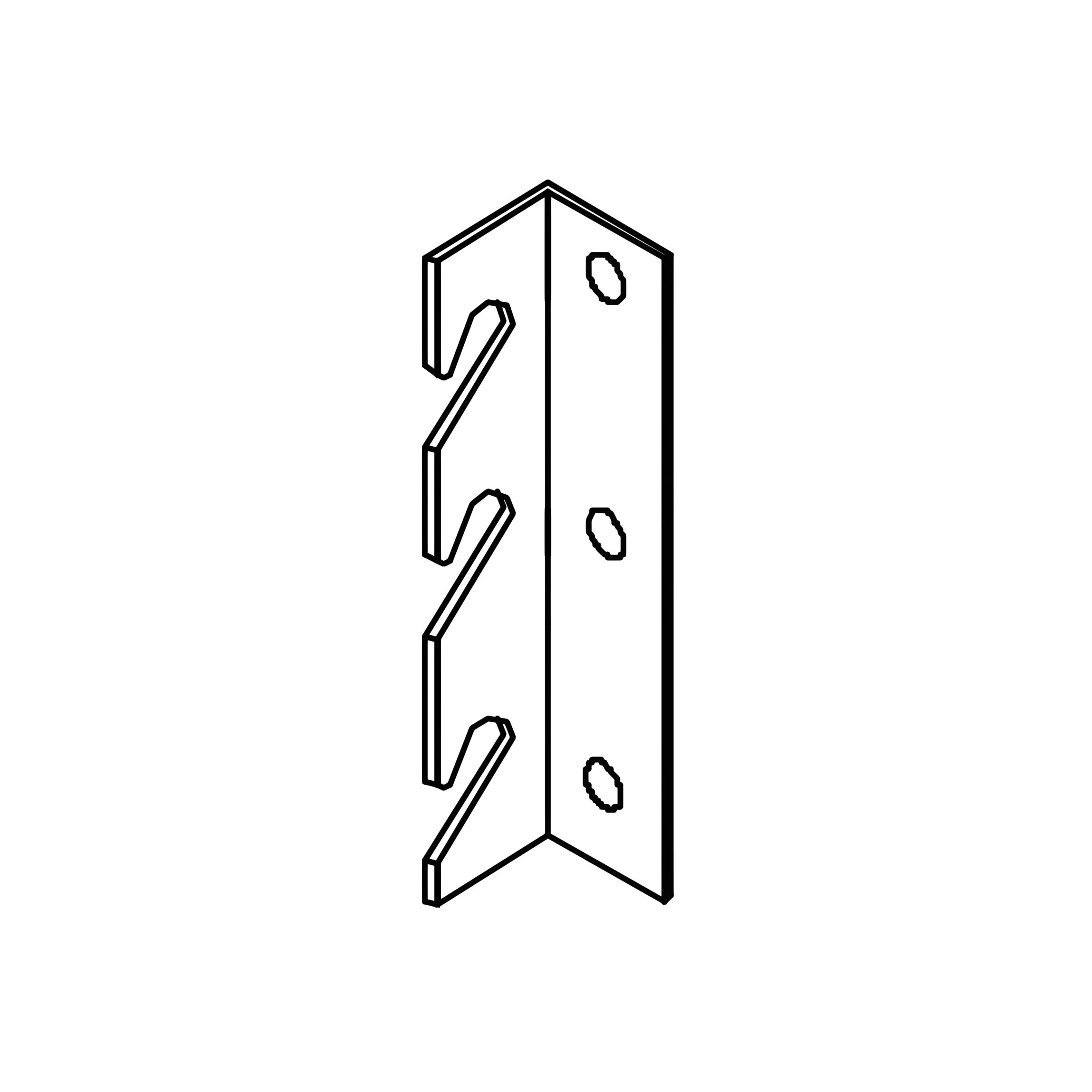
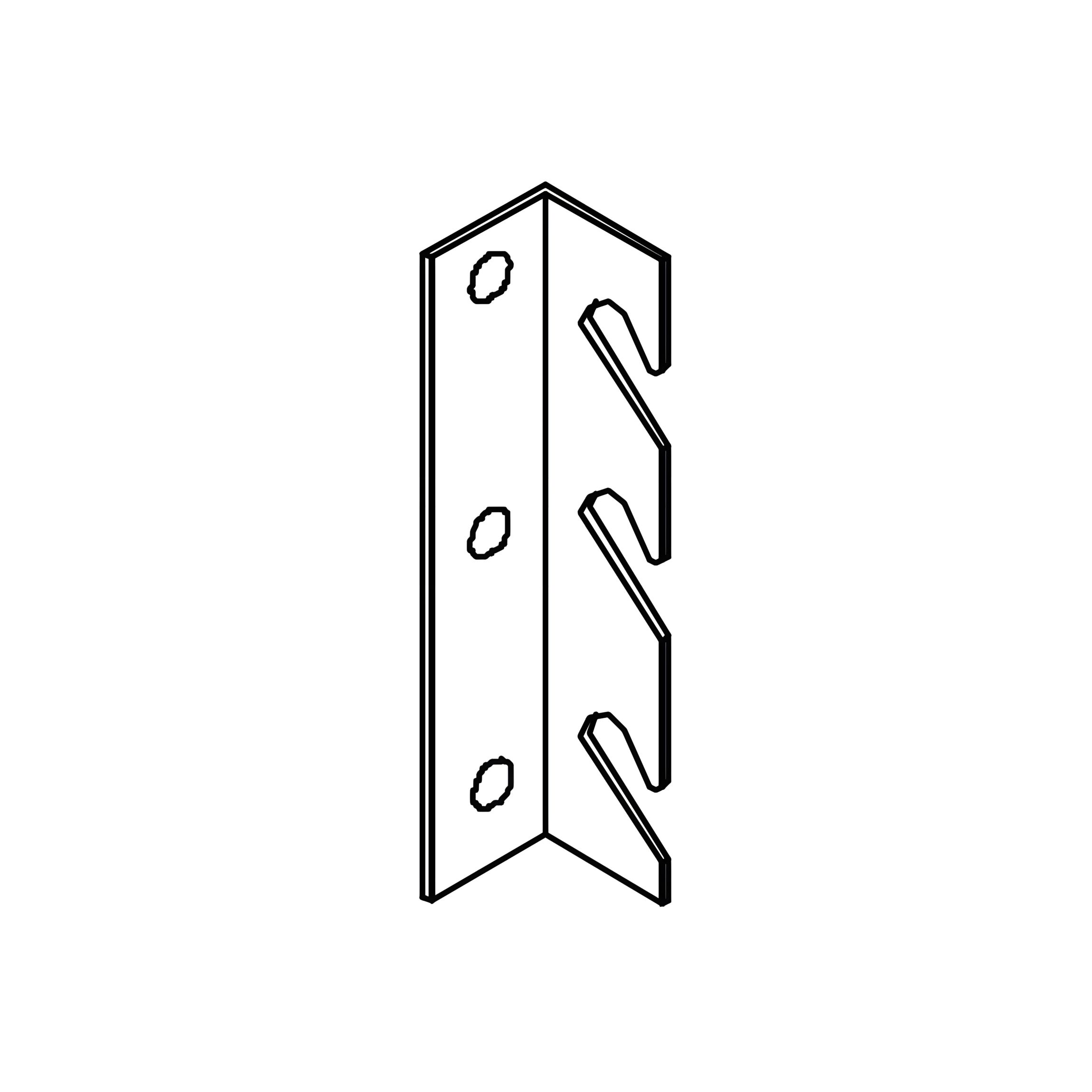
G - Corner Hook Bracket - Left
H - Corner Hook Bracket - Right
I - Allen Key for M8 Bolts
J - Spanner for M8 Nuts
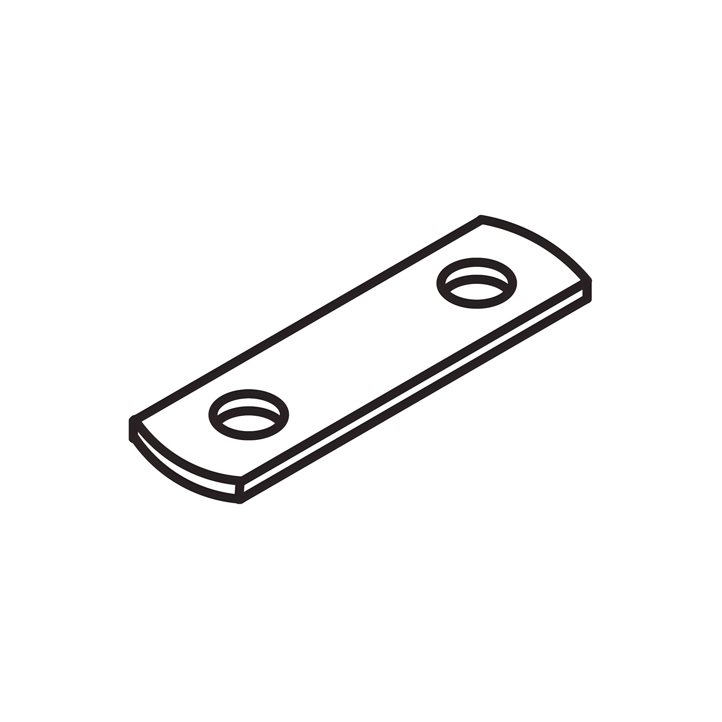
K - Metal Connection Plates For Slat Frame
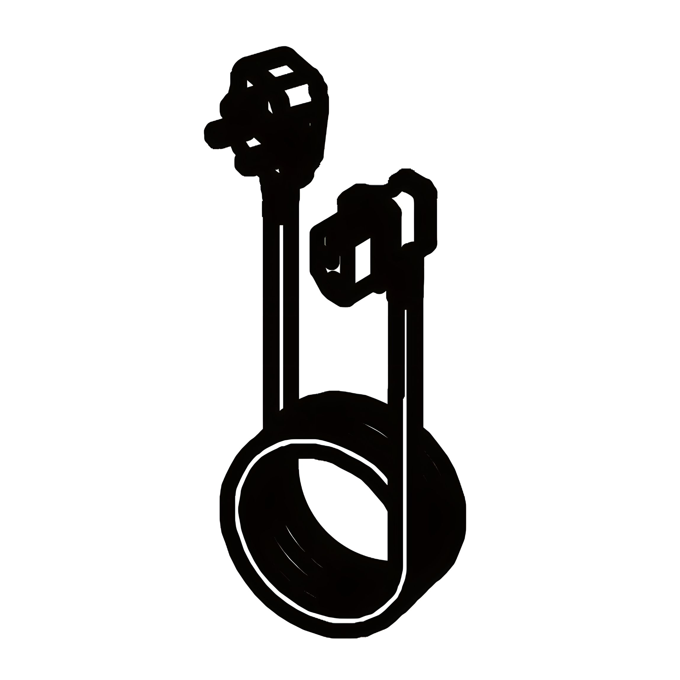
L - Mains Power Lead
M - Cable Clip
N - TV Support slide
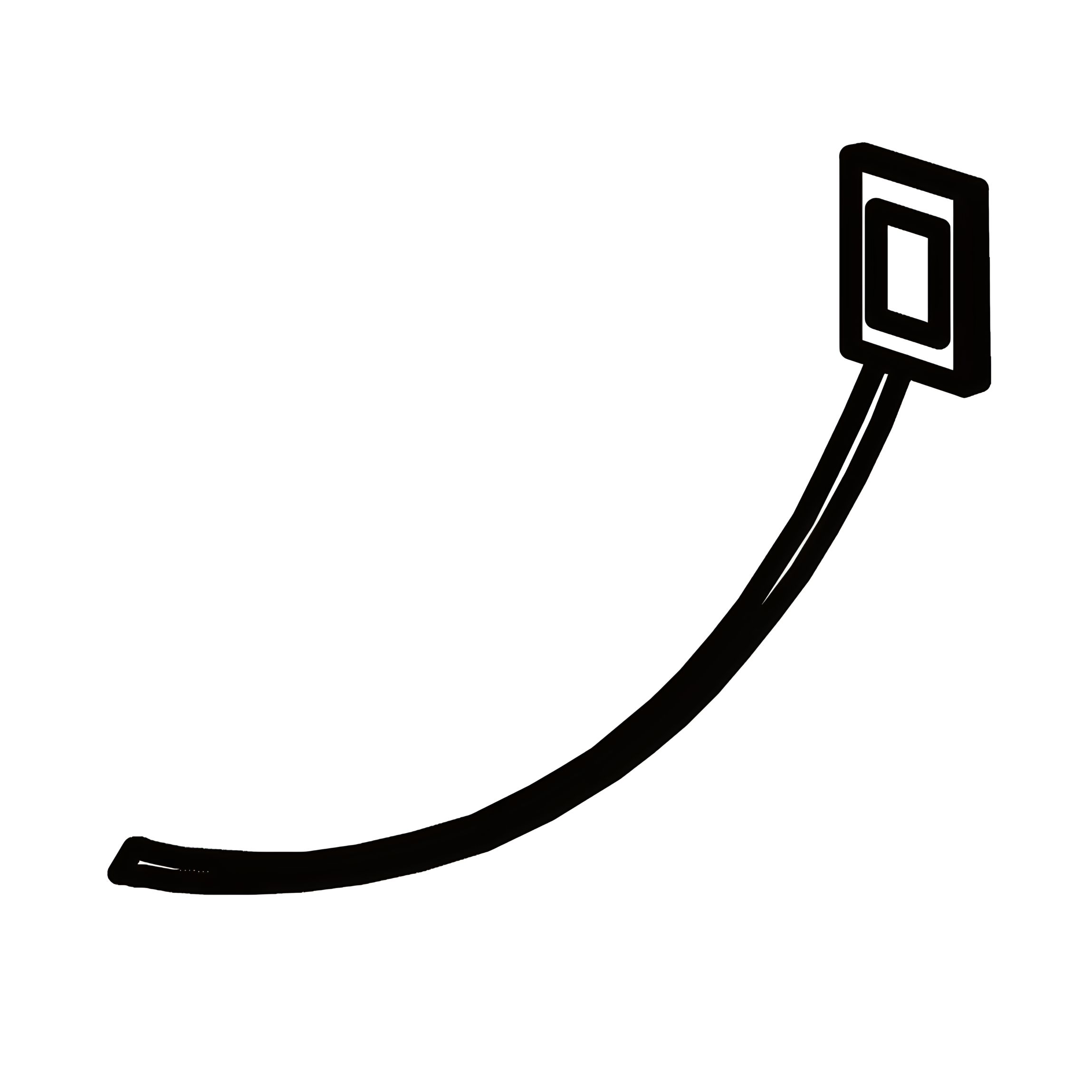
O - Cable Tie
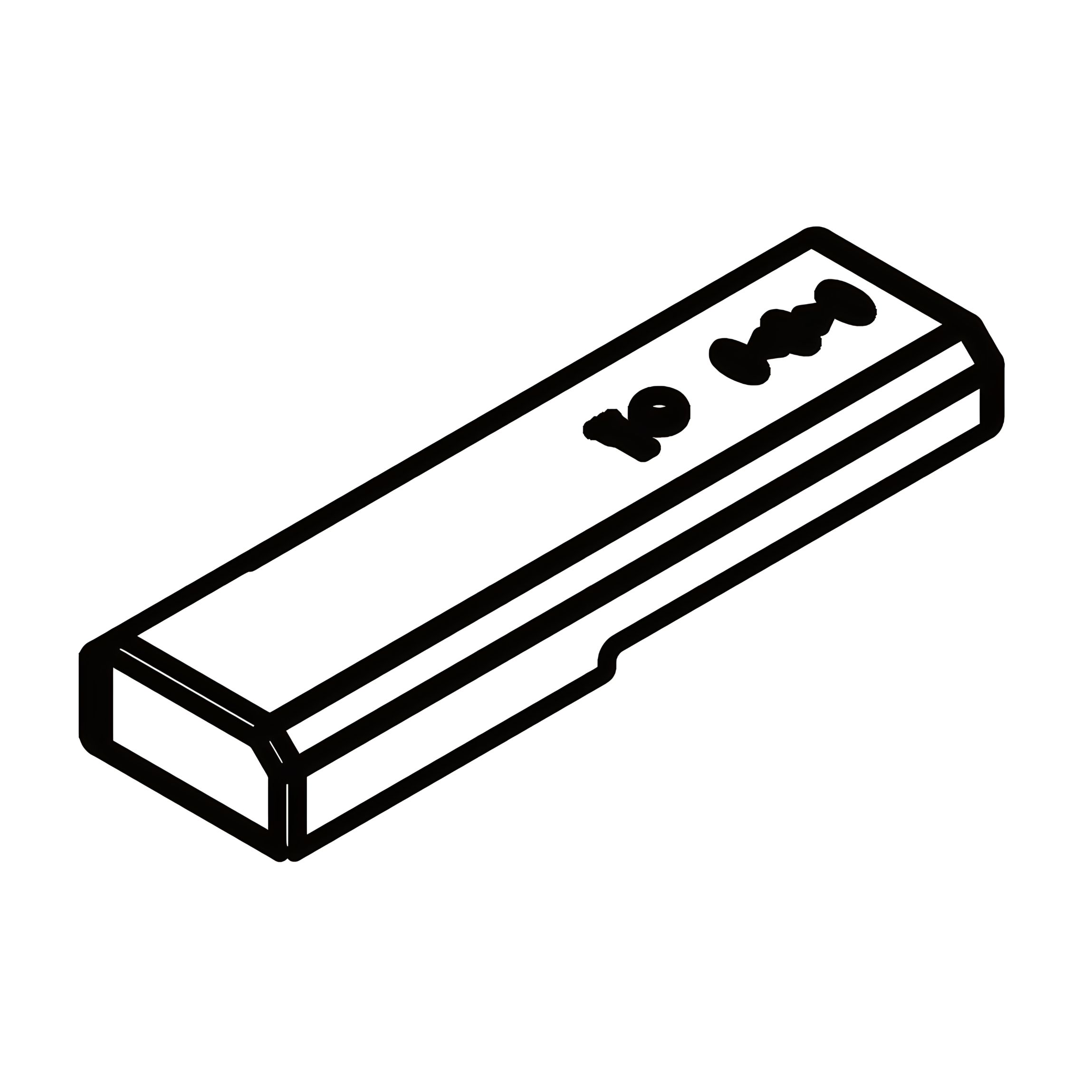
P - Remote Control
R - HDMI 90° Adapter
Y - Bolt sets (M8 x25mm)
Y - Counter sunk screw sets (M 4 x12mm)
Y - Counter sunk screw sets (6x12mm)
Z - Allen Key (2.5 mm)
Z - Allen Key (4 mm)
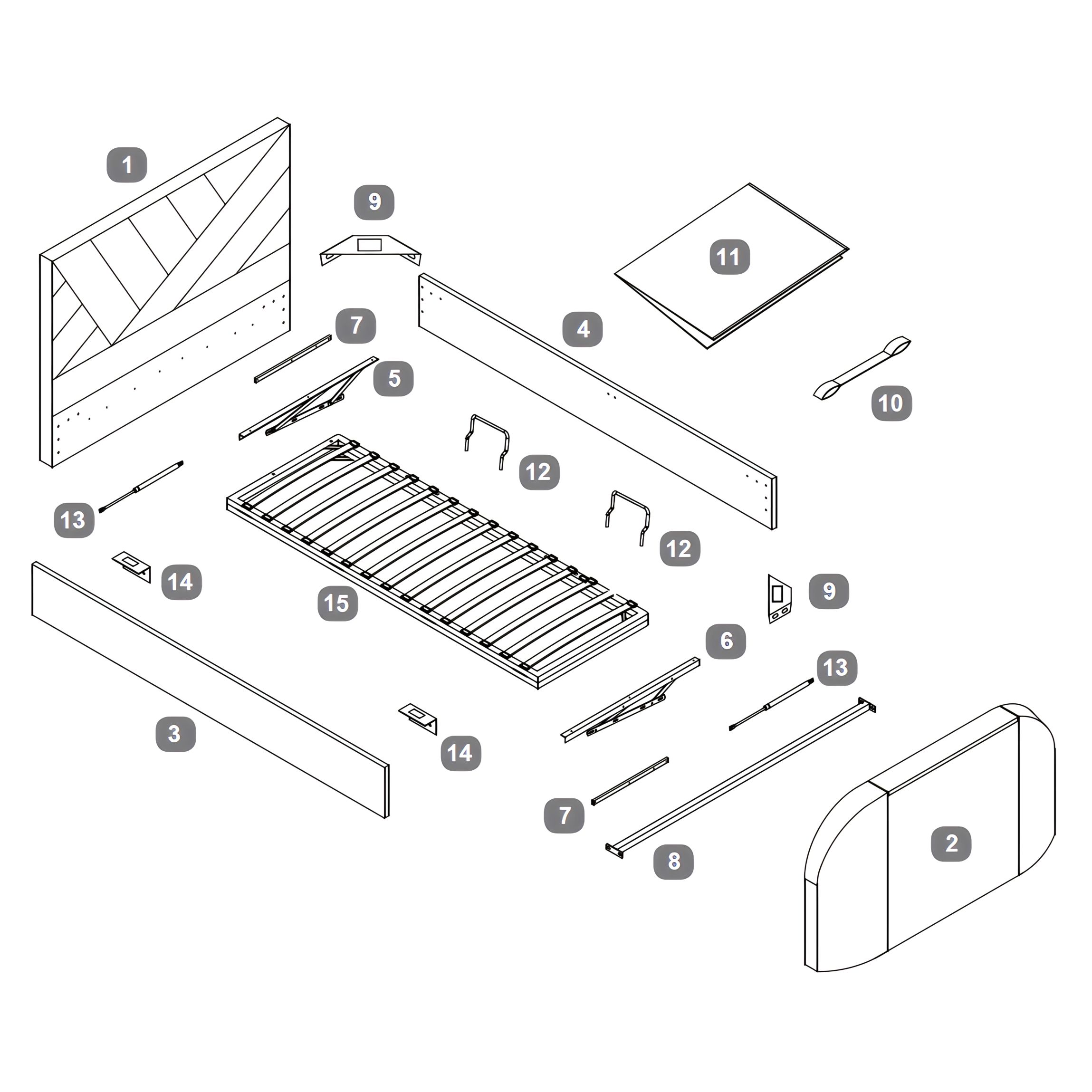
Parts
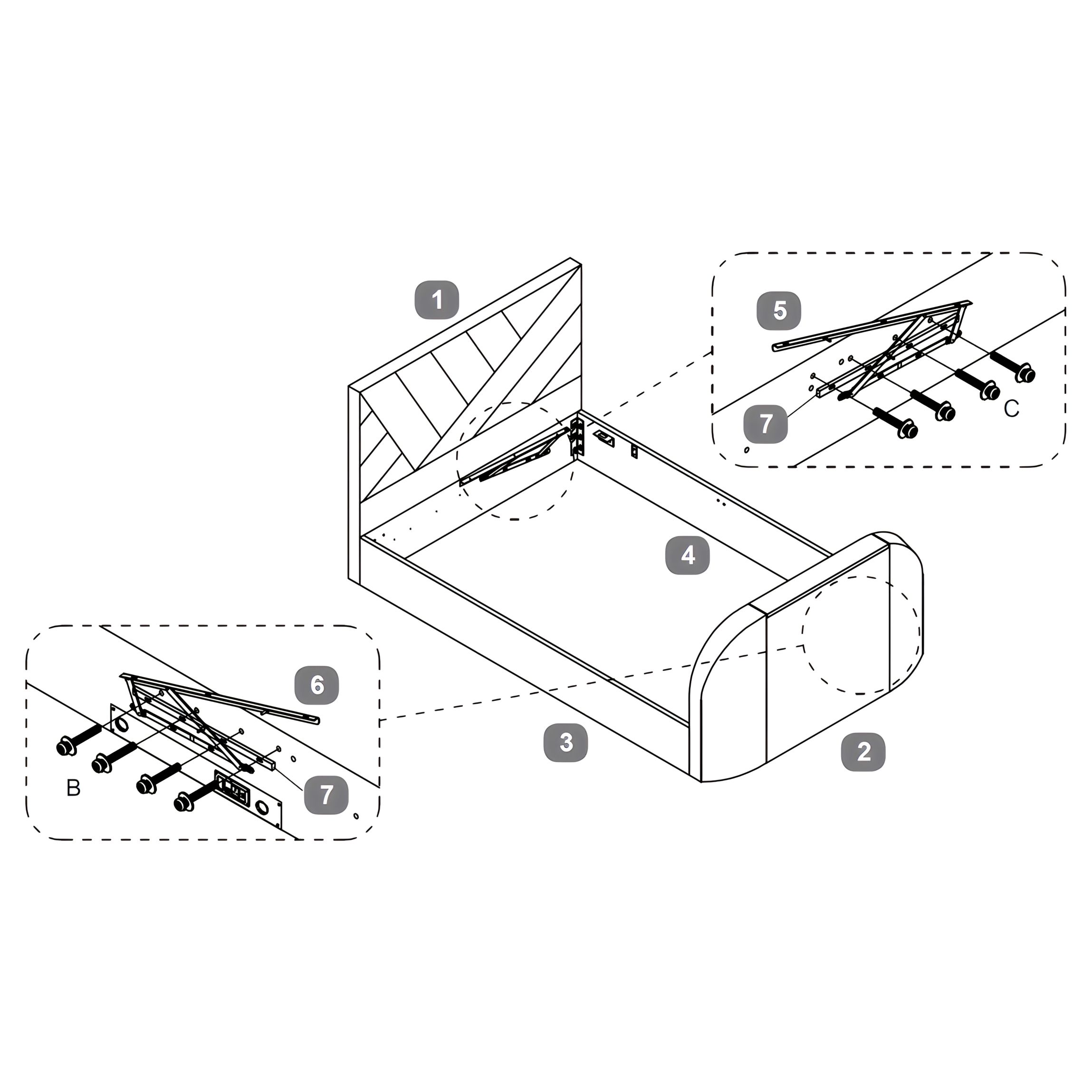
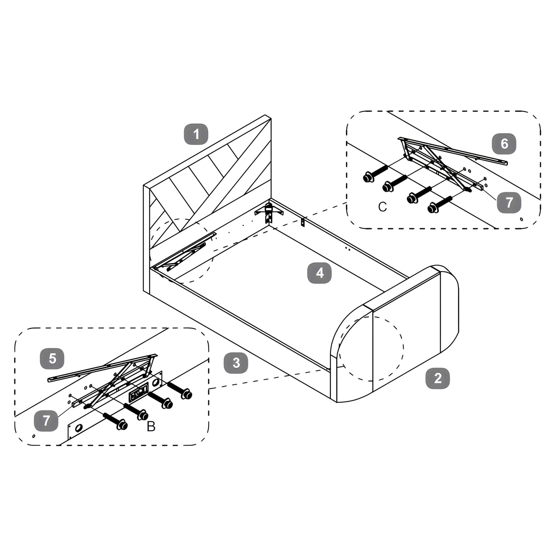
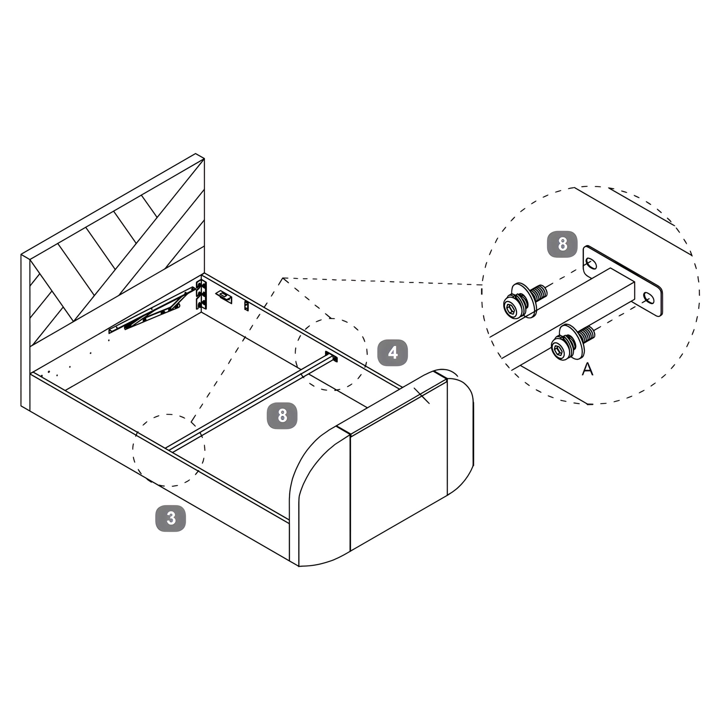
1Headboard
2Footboard
3Side Rail - Left
4Side Rail - Right
5Gas-lift Mechanism - Left
6Gas-lift Mechanism - Right
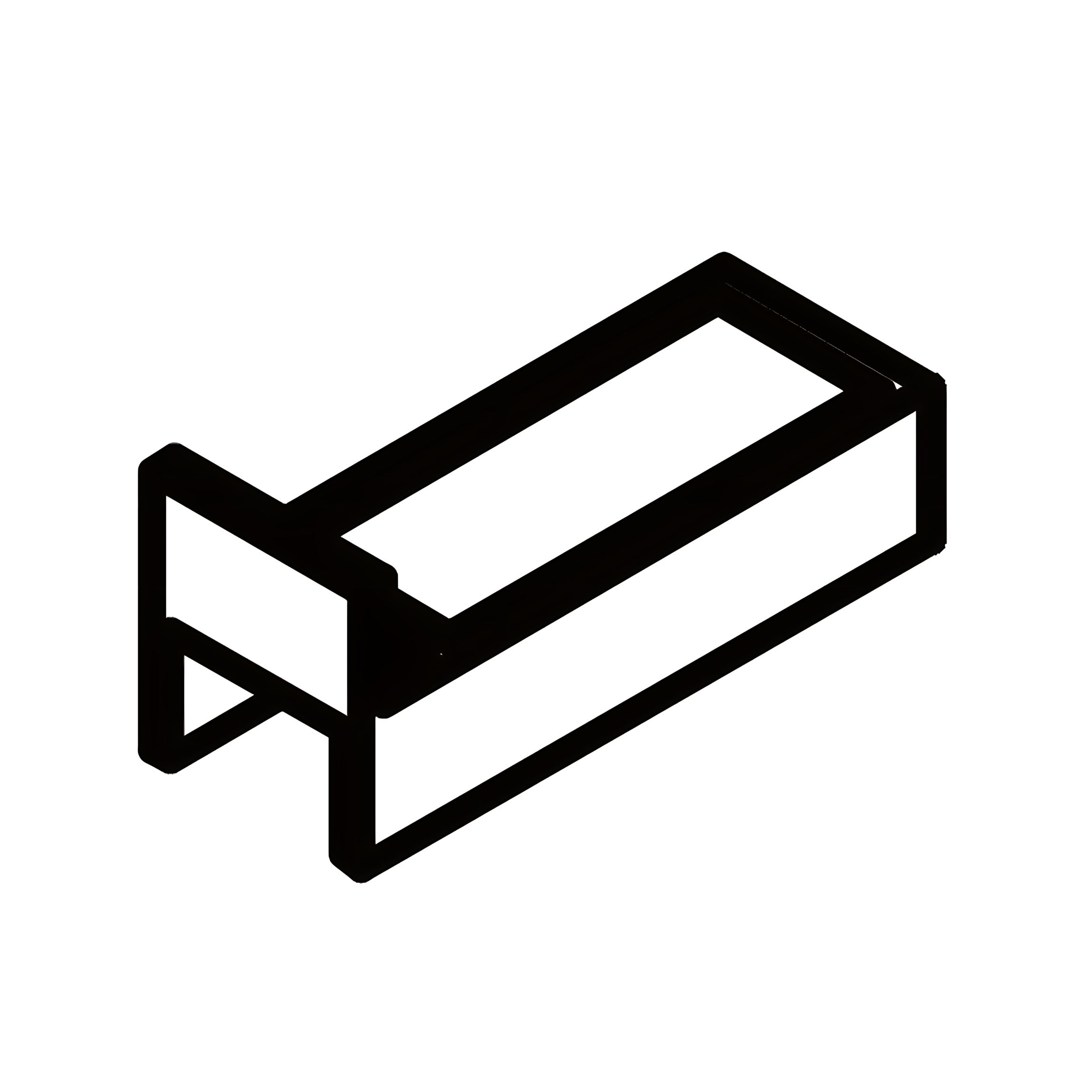
7Spacer Rail For Gas Lift Mechanism
8Side Rail Cross Bar
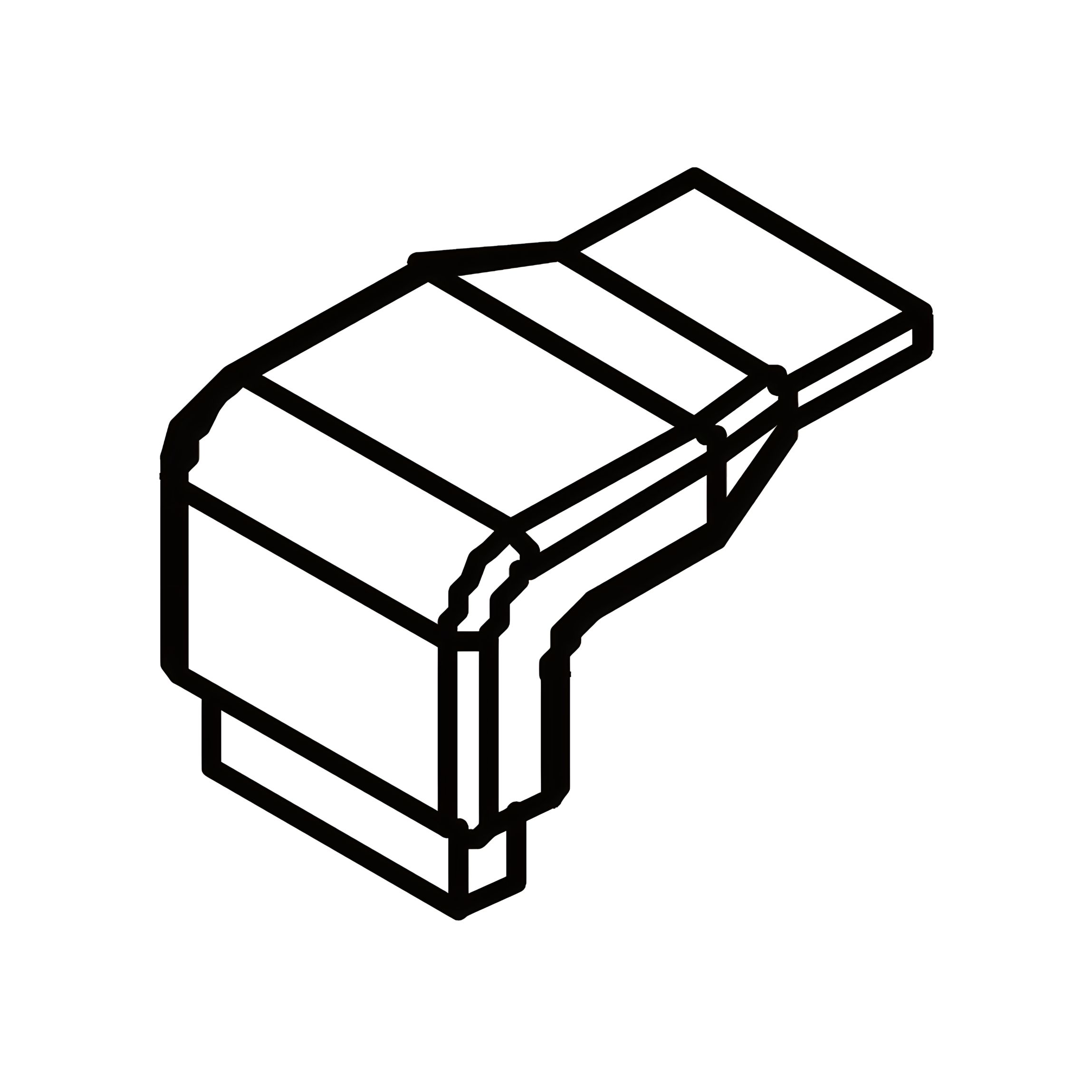
9Angled Corner Bracket
10Fabric Hand Strap
11Fabric Base Cover
12Mattress Stopper
13Gas-lift Piston
14'L' Shape Bracket
15Metal Slat Frame
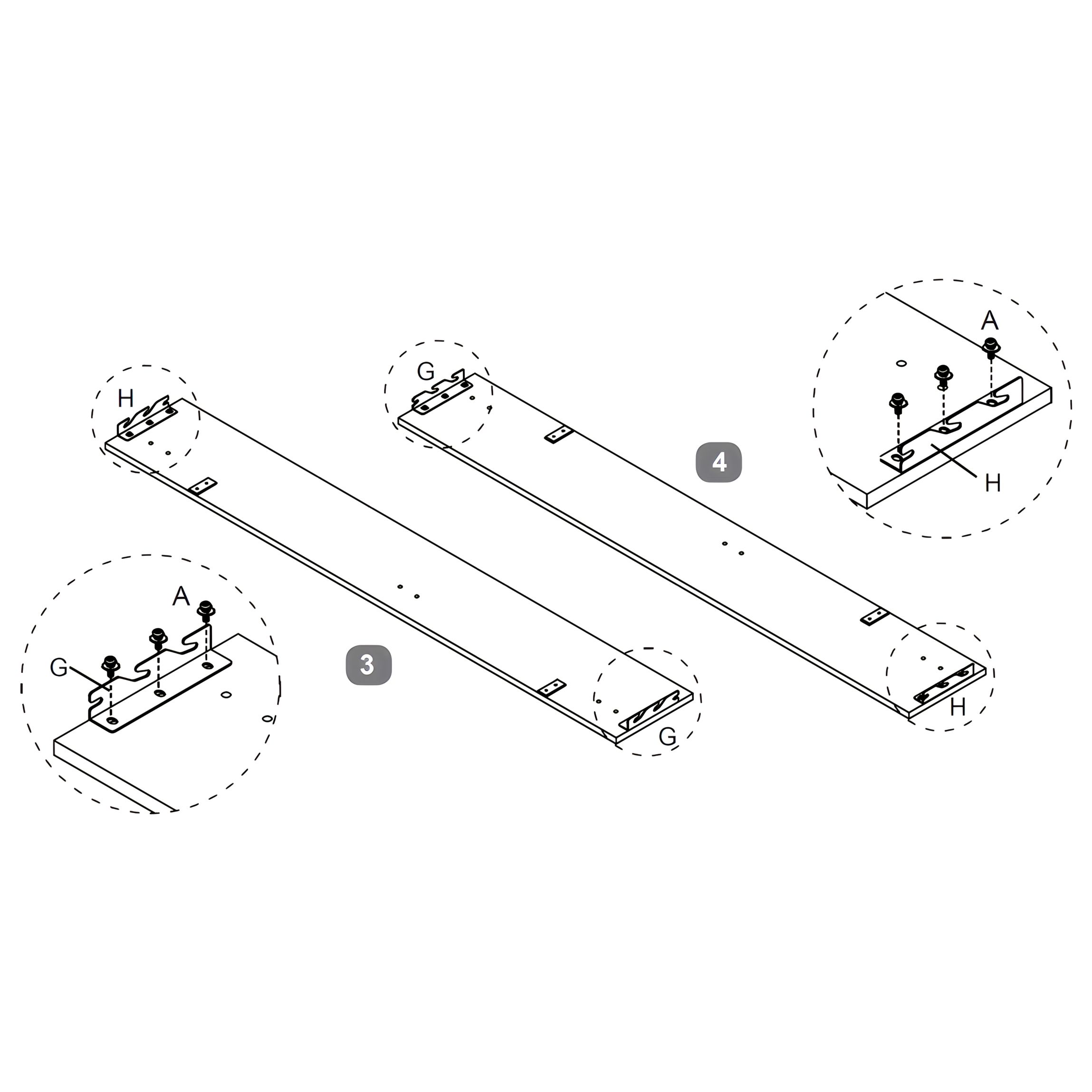
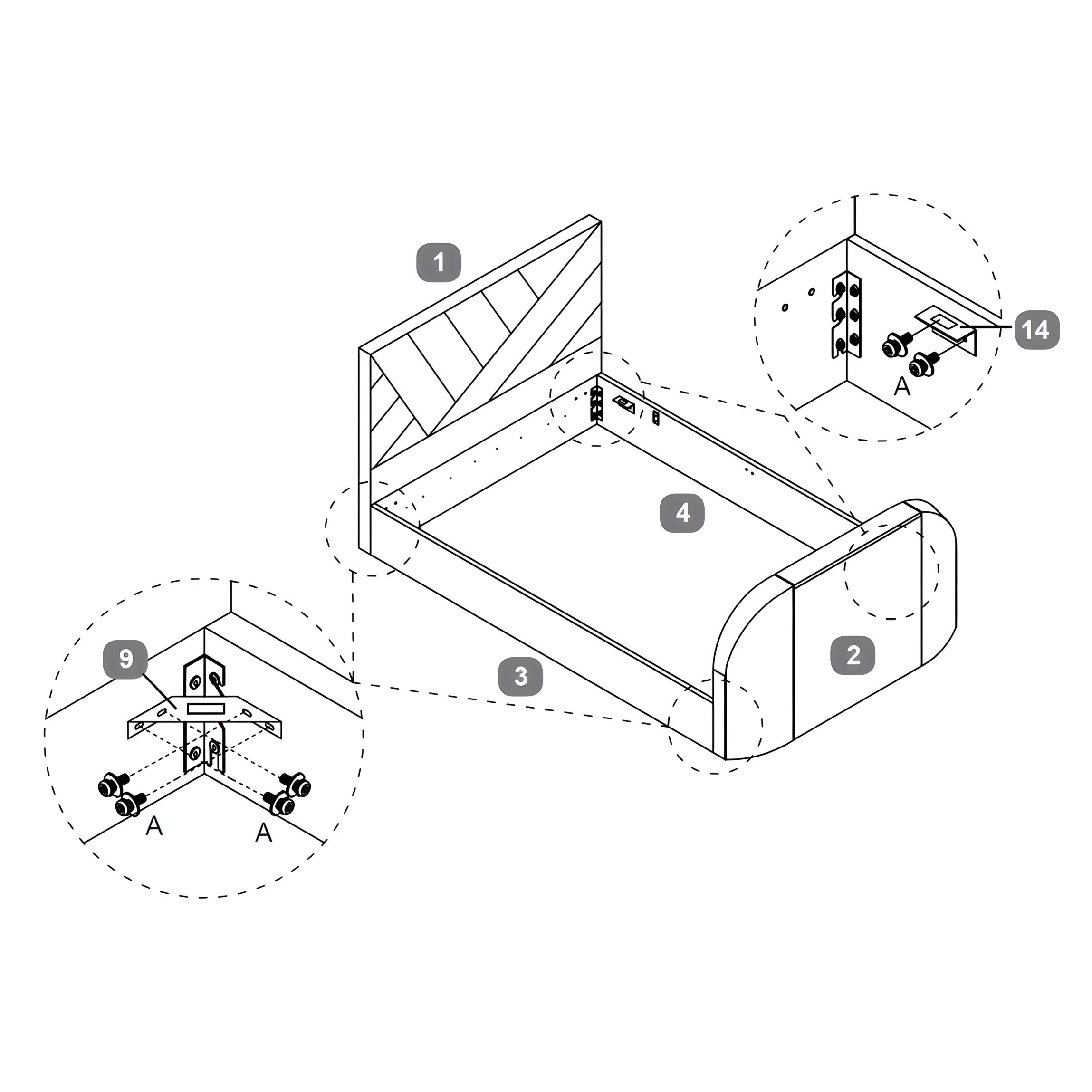
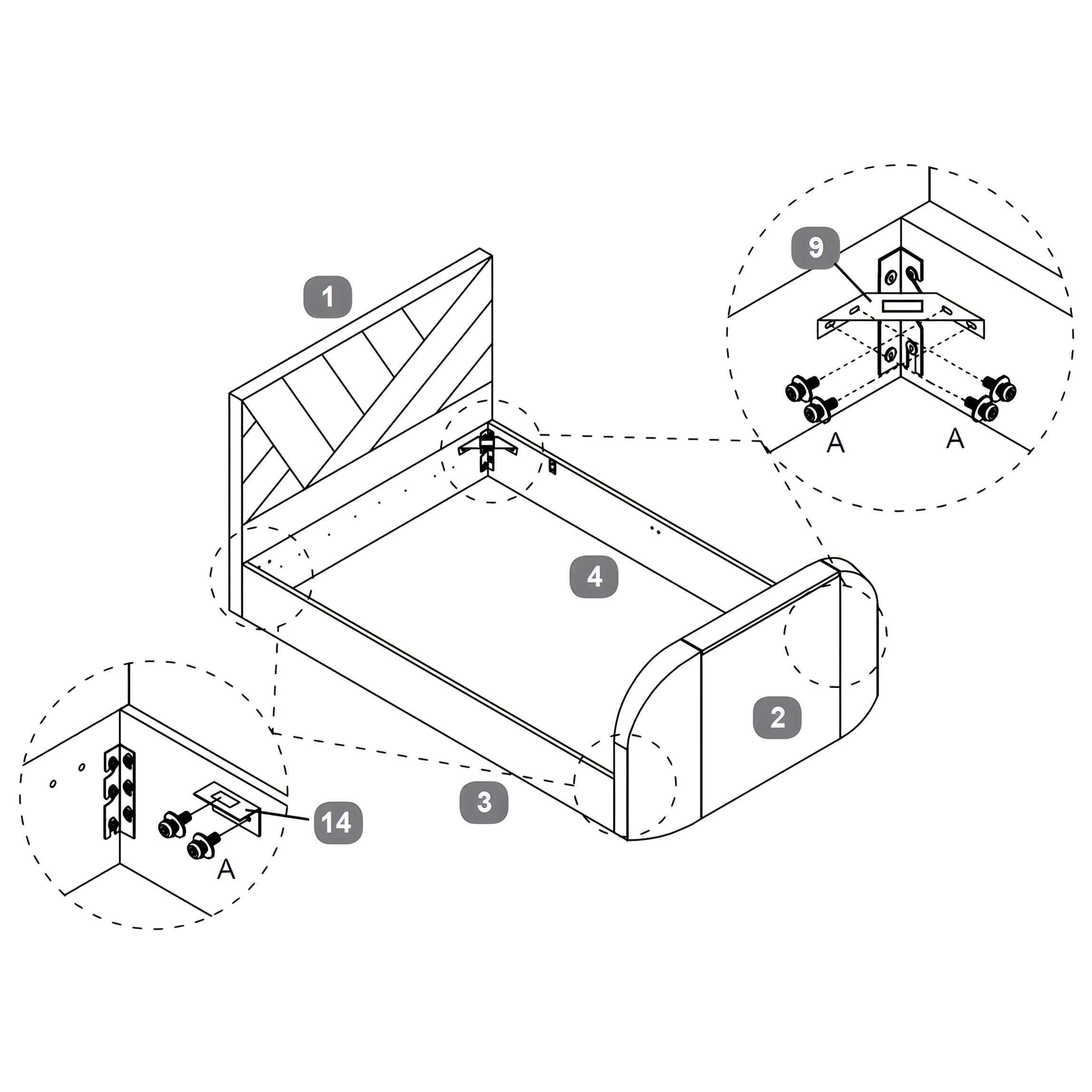
1. Attach Corner Hook Brackets to Side Rails
1. Position the Side Rail – Left (3) and Side Rail – Right (4) flat with the inside facing up. 2. Attach one Corner Hook Bracket – Left (G) and one Corner Hook Bracket – Right (H) to each end of the side rails. 3. Secure each bracket with 2 × Bolt (A) per side using the Allen Key (I).
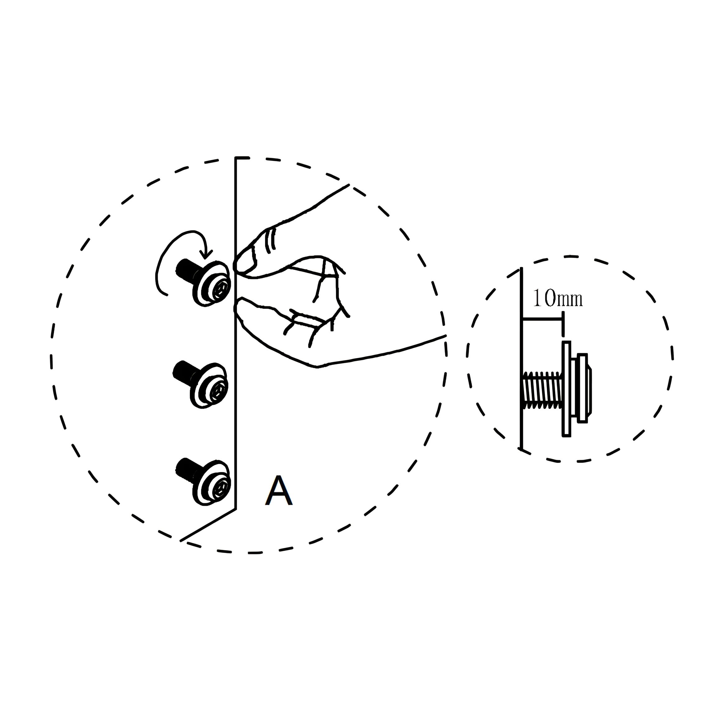
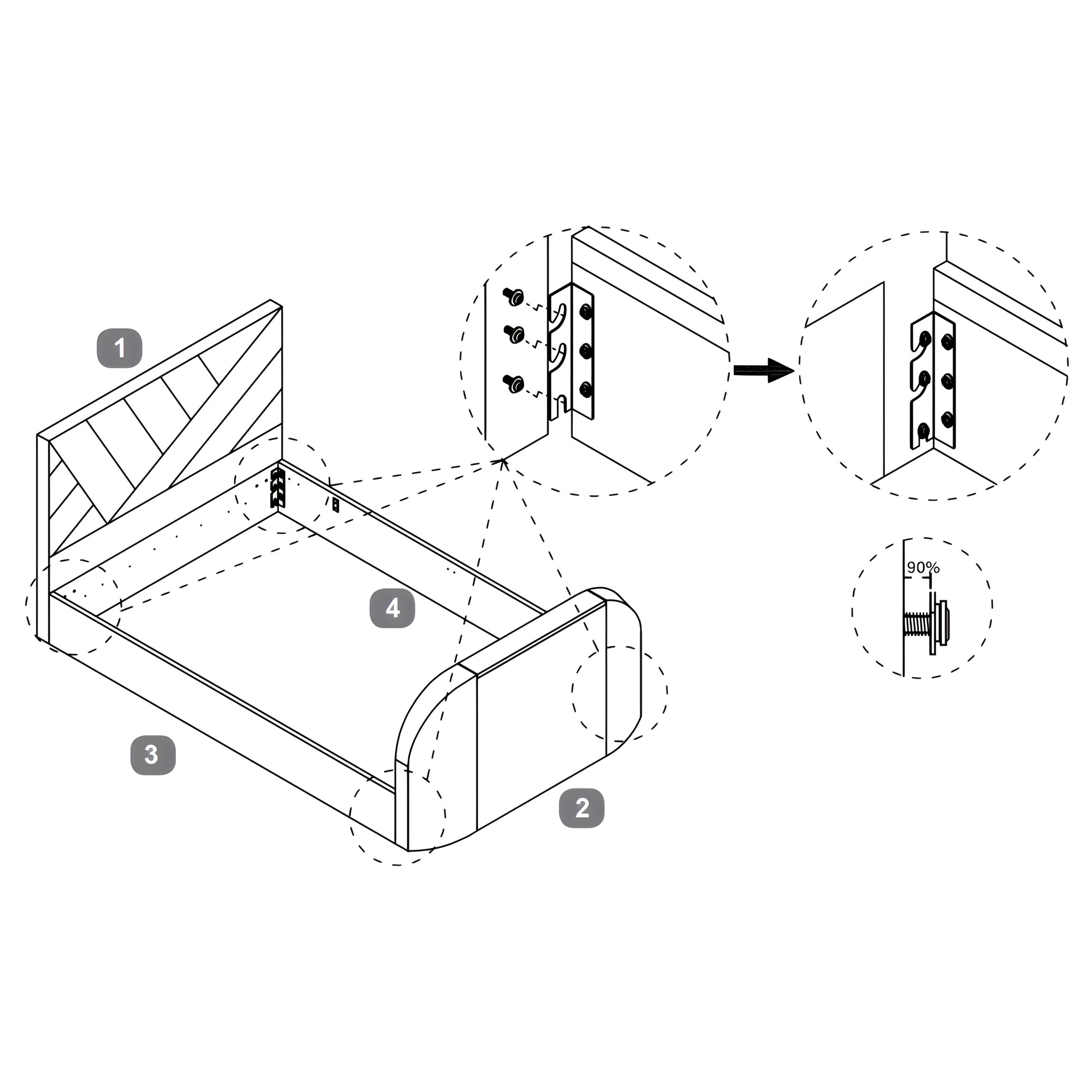
2. Connect Side Rails to Headboard and Footboard
1. Insert Bolts (A) halfway into the pre-drilled holes on the Headboard (1) and Footboard (2), leaving about 10 mm exposed. 2. Hook the Side Rail – Left (3) and Side Rail – Right (4) onto the bolts using the installed Corner Hook Brackets (G, H). 3. Once aligned, tighten all bolts with the Allen Key (I) until secure.
3. Install Brackets (Left Opening)
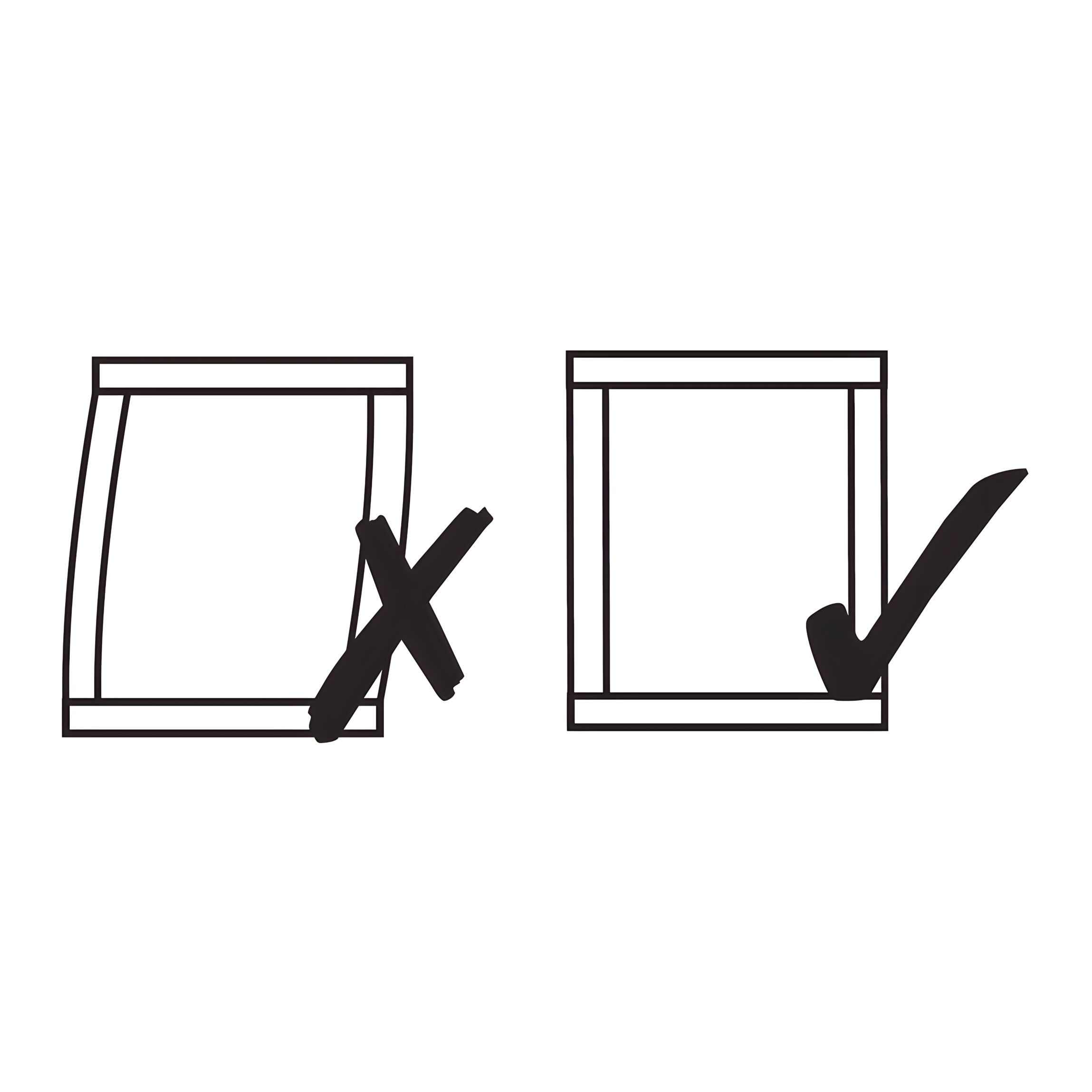
1. On the Side Rail – Right (4) (opposite the opening side), attach the ‘L’ Shape Brackets (14) using Bolts (A). 2. On the corners of the Side Rail – Left (3) and Headboard (1), fix the Angled Corner Brackets (9) using Bolts (A). 3. Check that all brackets sit flush and are securely fixed.
Important: Make certain the bed is squared up as shown in the diagram, then tighten all bed assembly bolts 100%
4. Install Brackets (Right Opening)
1. On the Side Rail – Left (3) (opposite the opening side), attach the ‘L’ Shape Brackets (14) using Bolts (A). 2. On the corners of the Side Rail – Right (4) and Headboard (1), fix the Angled Corner Brackets (9) using Bolts (A). 3. Check that all brackets sit flush and are securely fixed.
Important: Make certain the bed is squared up as shown in the diagram, then tighten all bed assembly bolts 100%.
5. Install Gas-lift Mechanisms (Left Opening)
1. Position the Gas-lift Mechanism – Left (5) and Spacer Rail for Gas-lift Mechanism (7) inside the Side Rail – Left (3). 2. Secure the mechanism to the side rail using 3 × Bolt (C). 3. Repeat on the Side Rail – Right (4) with the Gas-lift Mechanism – Right (6) and Spacer Rail (7), fixing with 3 × Bolt (B).
6. Install Gas-lift Mechanisms (Right Opening)
1. Position the Gas-lift Mechanism – Left (5) and Spacer Rail for Gas-lift Mechanism (7) inside the Side Rail – Right (4). 2. Place the Spacer Rails (7) between the bed frame and the lift mechanism brackets, ensuring they sit underneath the gas-lift mechanism. 3. Secure the mechanism to the side rail using 3 × Bolt (B). 4. Repeat on the Side Rail – Left (3) with the Gas-lift Mechanism – Right (6) and Spacer Rail (7), fixing with 3 × Bolt (C).
7. Attach Side Rail Cross Bar
1. Position the Side Rail Cross Bar (8) between the Side Rail – Left (3) and Side Rail – Right (4). 2. Secure each end of the cross bar using 2 × Bolt (A), each with a Spring Washer (E) and Flat Washer (F). 3. Tighten the bolts with the Allen Key (I) until secure.
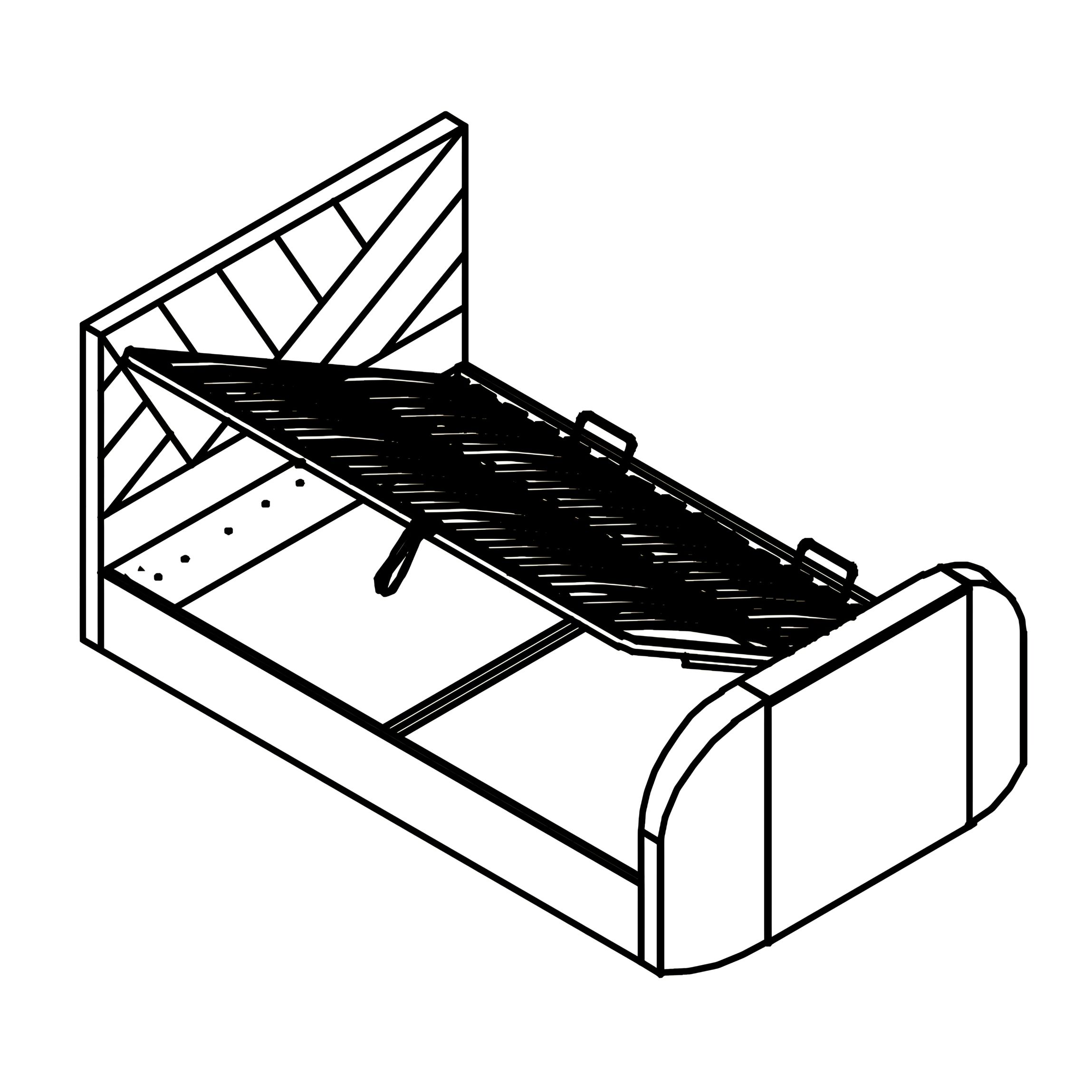
8. Place Fabric Base Cover
1. Lay the Fabric Base Cover (11) flat inside the bed frame, positioning it above the floor area and below the Side Rail Cross Bar (8). 2. Adjust the cover so it sits evenly across the frame and fits neatly against all sides.
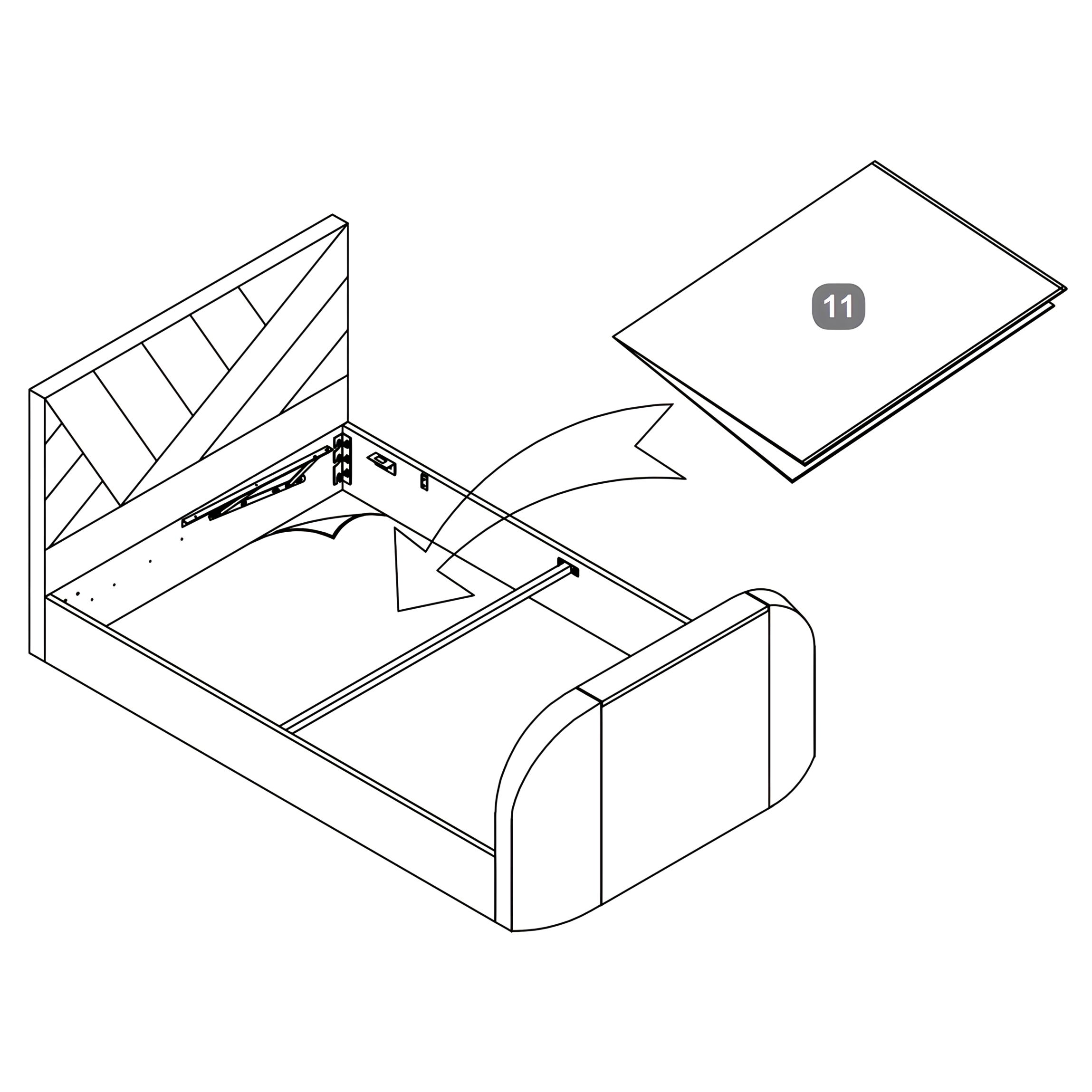
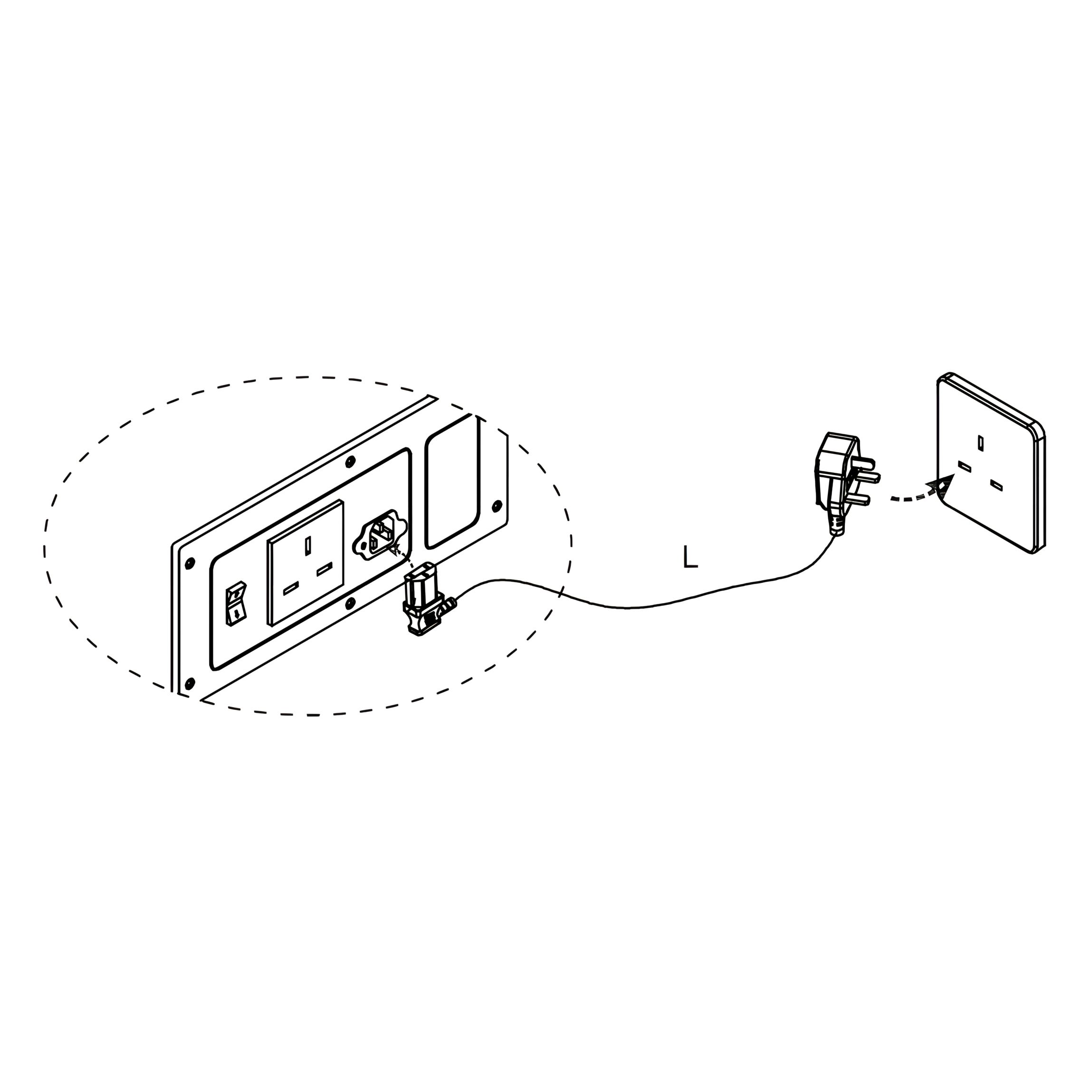
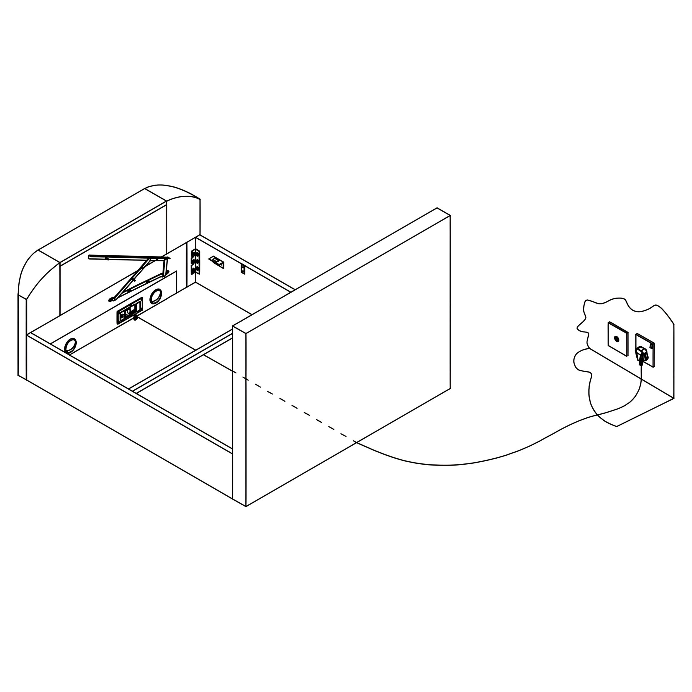
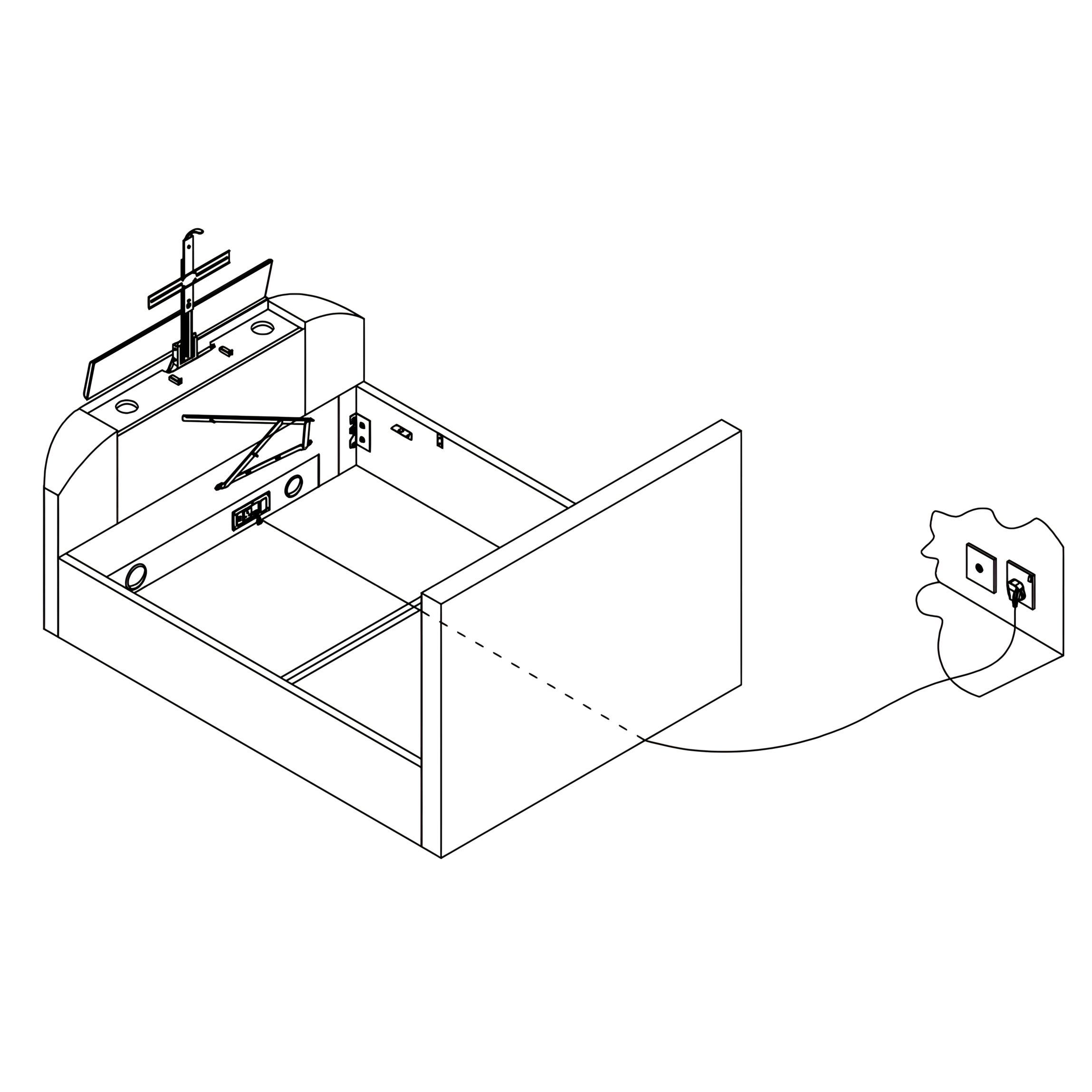
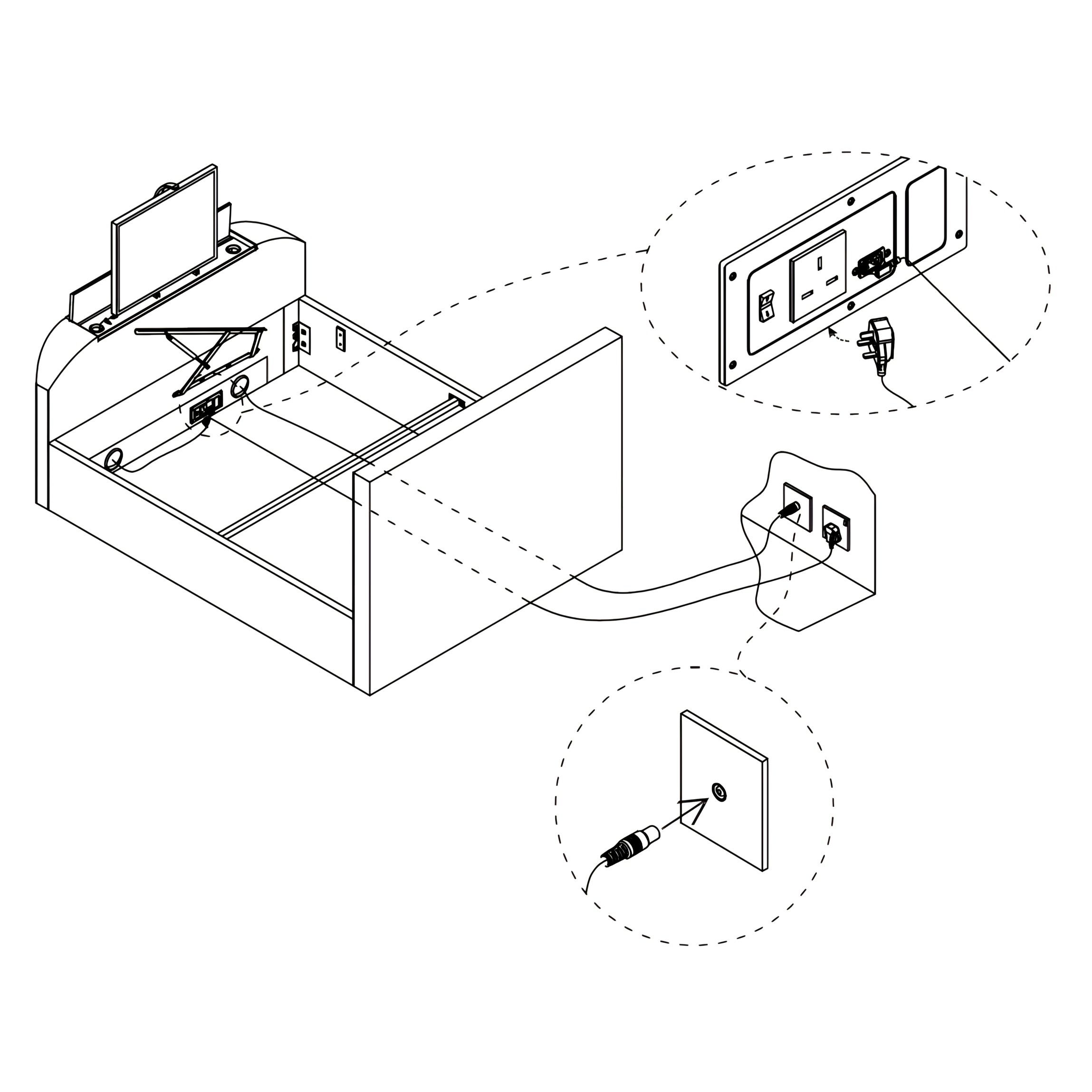
9. Connect Mains Power Lead
1. Locate the power socket inside the Footboard (2). 2. Plug in the Mains Power Lead (L). 3. Connect the other end of the power lead to your wall socket.
Important: Connect the mains power lead (L) to your wall socket – for safety this must be an earthed power supply.
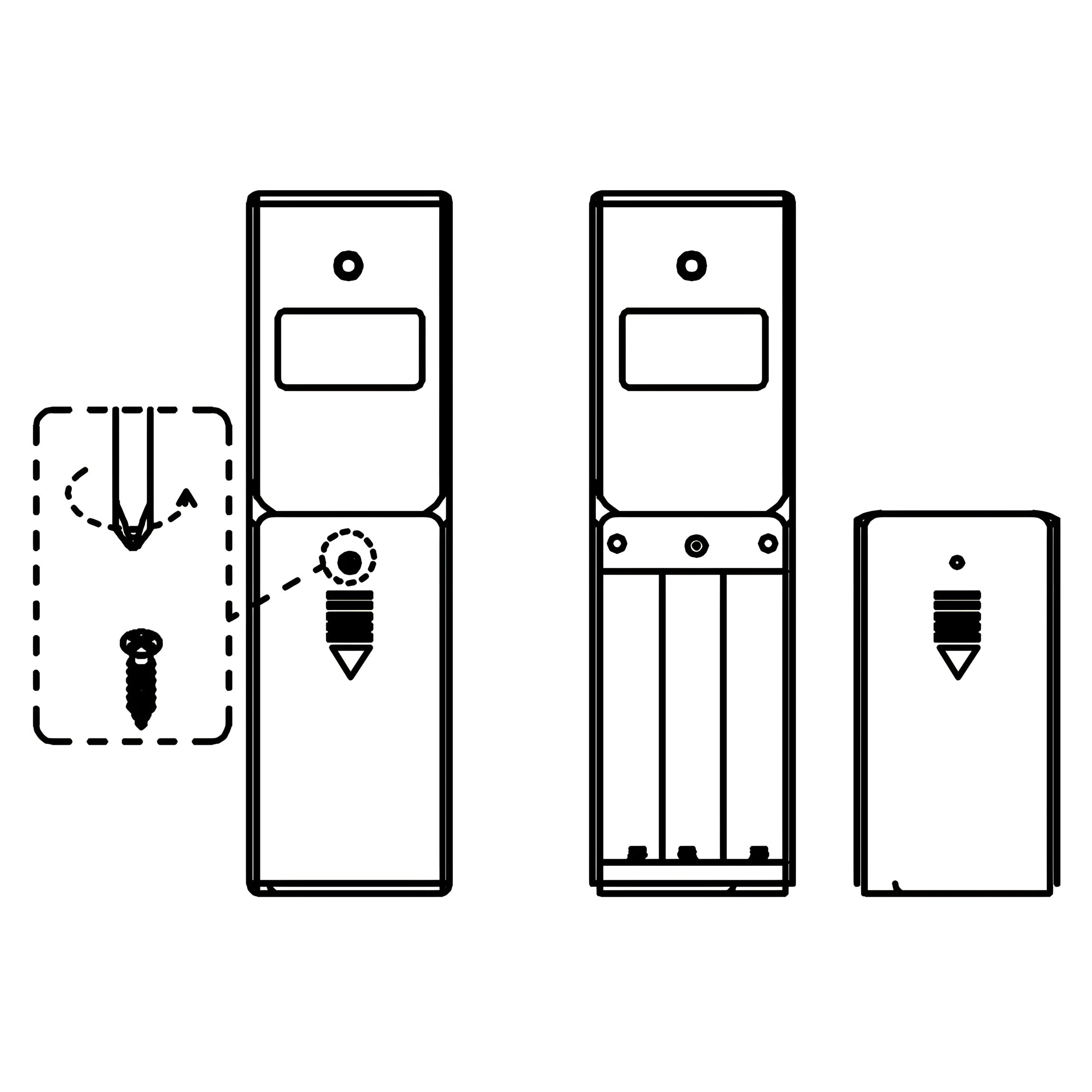
10. Insert Batteries into Remote Control
1. Remove the screw and slide off the cover of the Remote Control (P). 2. Insert 3 × AAA batteries into the compartment, following the polarity markings. 3. Refit the cover and secure it with the screw.
Tip: Use fresh alkaline batteries for best performance.
11. Pair Remote Control to TV Lift
The Remote Control (P) is supplied pre-paired to your TV Lift. If the connection is lost, follow these steps:
1. Remove the screw and cover. 2. Insert 3 × AAA batteries, then refit the cover and screw. 3. Disconnect all mains electric power to the bed for at least 60 seconds. 4. Press and hold the UP or DOWN button on the remote control. 5. While holding the button, reconnect the mains power supply and continue holding for at least 5 seconds. 6. The TV Lift will begin to move in the selected direction, confirming the signal has been received. 7. Re-connection is now complete.
Tip: If pairing issues persist, repeat the steps ensuring the batteries are fresh and properly installed.
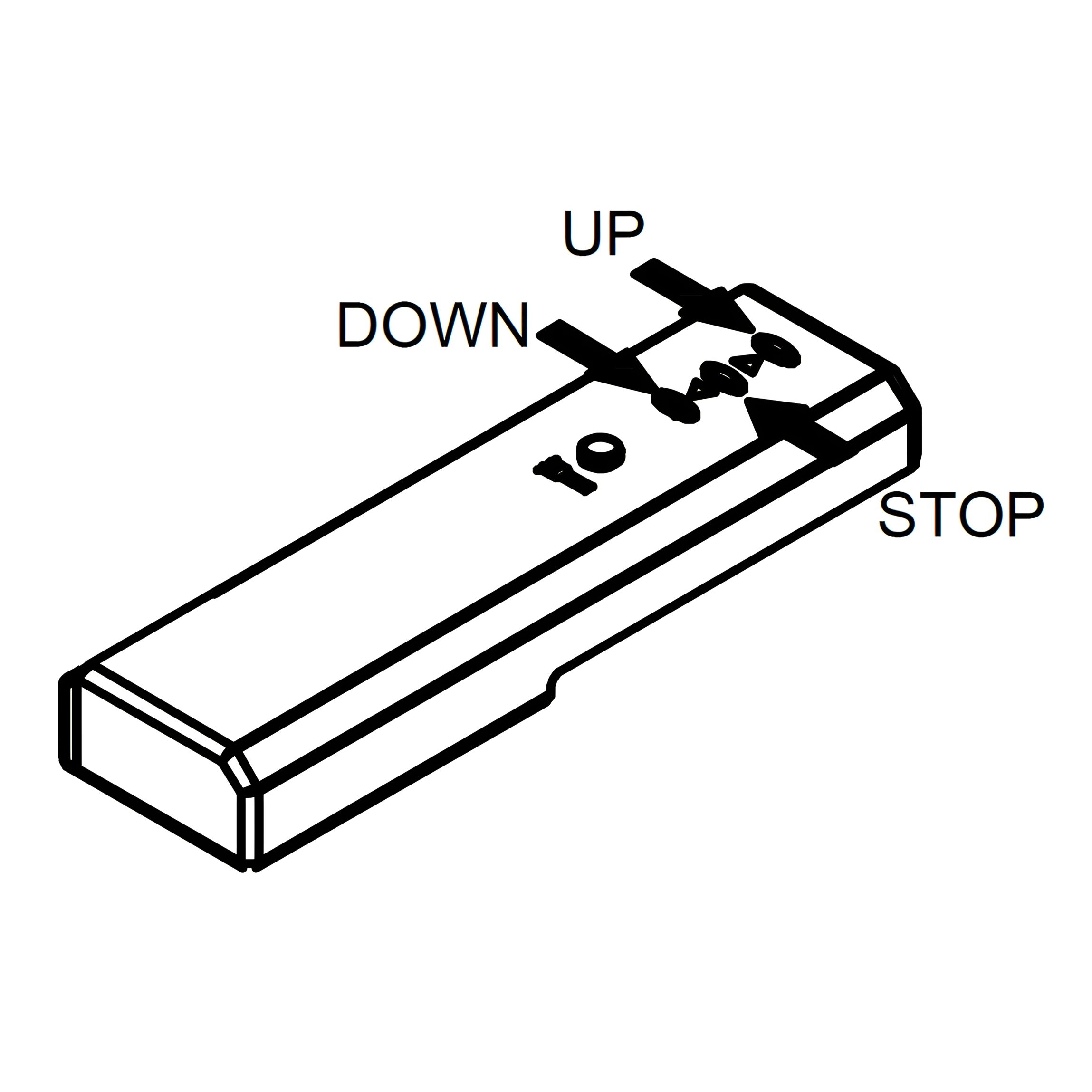
12. Raise the TV Lift
1. Ensure the Mains Power Lead (L) is connected and switched on. 2. On the Remote Control (P), press the “UP” button. 3. The TV lift inside the Footboard (2) will rise to the extended position.
Note: Wait until the lift is fully raised before continuing to the next step.
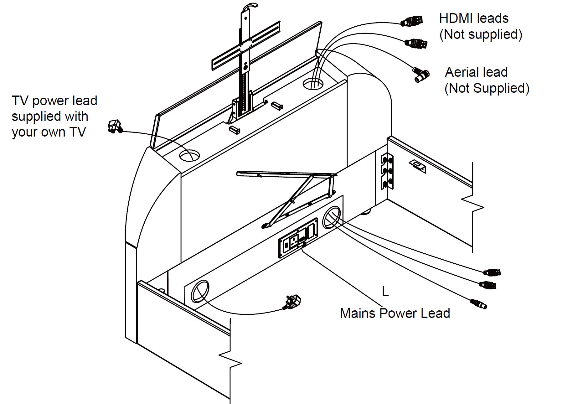
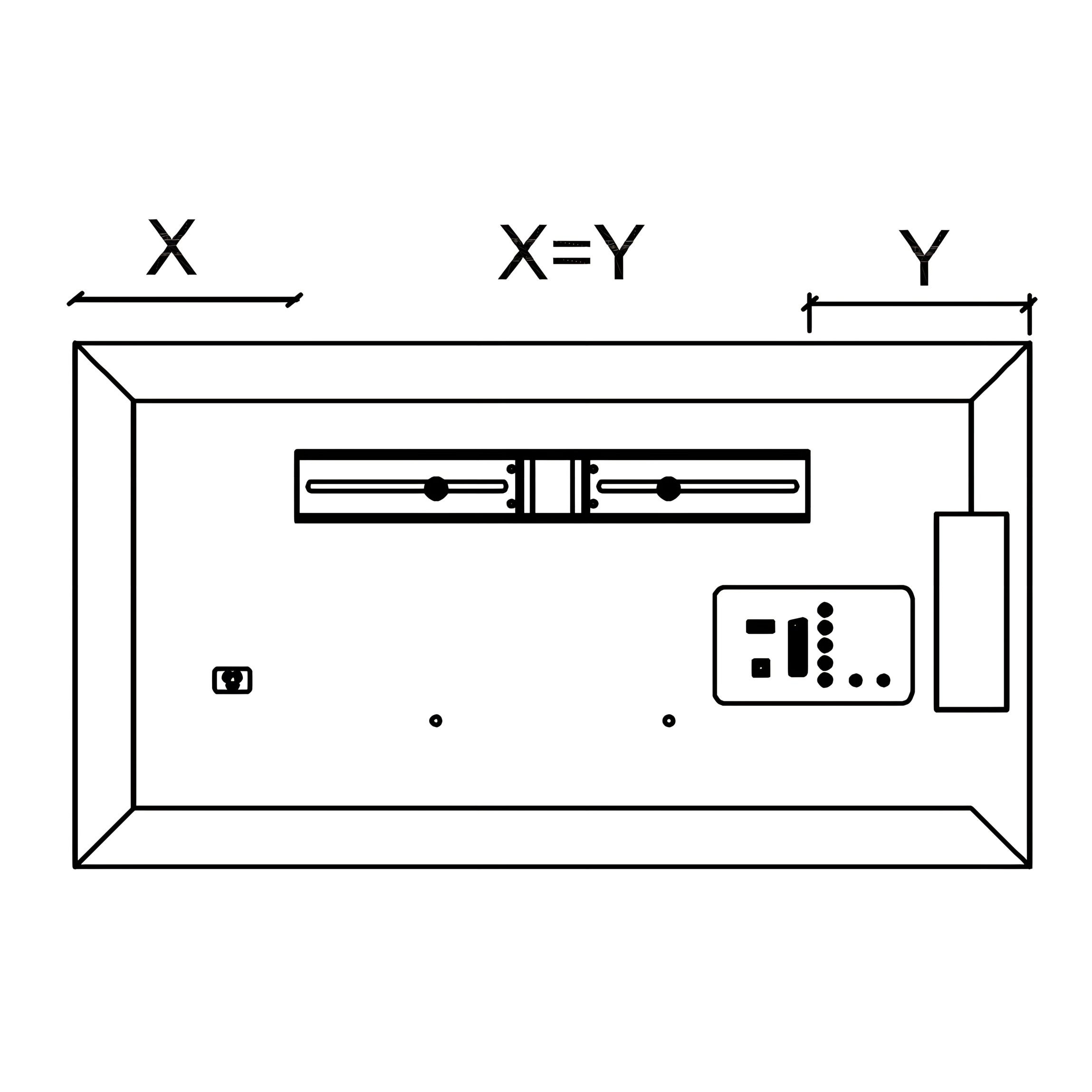
13. Prepare TV Connections
1. Identify the connection ports on the back of your TV. 2. Feed the necessary cables (e.g., TV power lead, HDMI leads, aerial lead) through the ducts at the top of the Footboard (2). 3. Select the duct that best aligns with your TV’s ports.
Tip: Before fitting the television, push any leads through each duct from the top. Choose the best side to use depending on where the connection ports are on back of your TV. Never cross cables from one side to the other.
Note: For illustration purposes only, TV connections may vary.
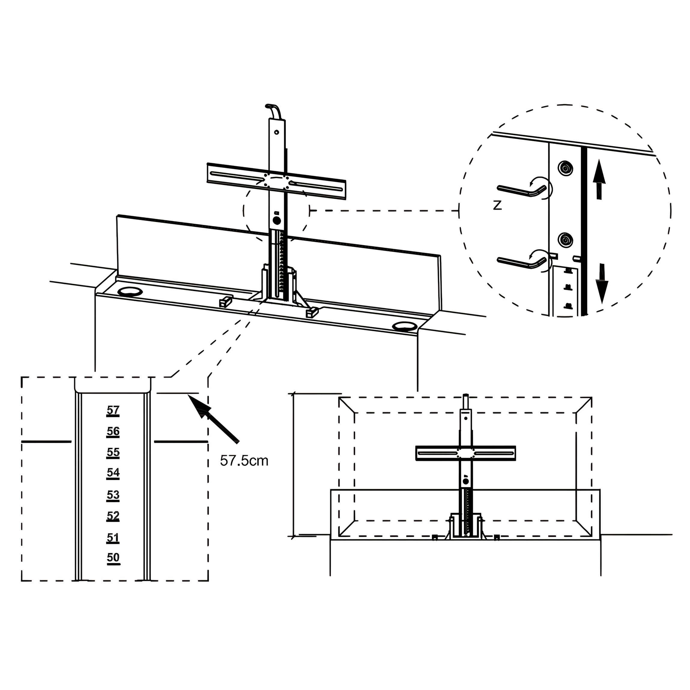
14. Set TV Height
1. Measure the height of your TV. The maximum allowed height is 57.5 cm. 2. Adjust the TV lift ruler to match the height of your TV. 3. Secure the setting with the Allen Key (Z).
Note: Maximum TV dimensions: W98 × H57.5 × D8 cm.
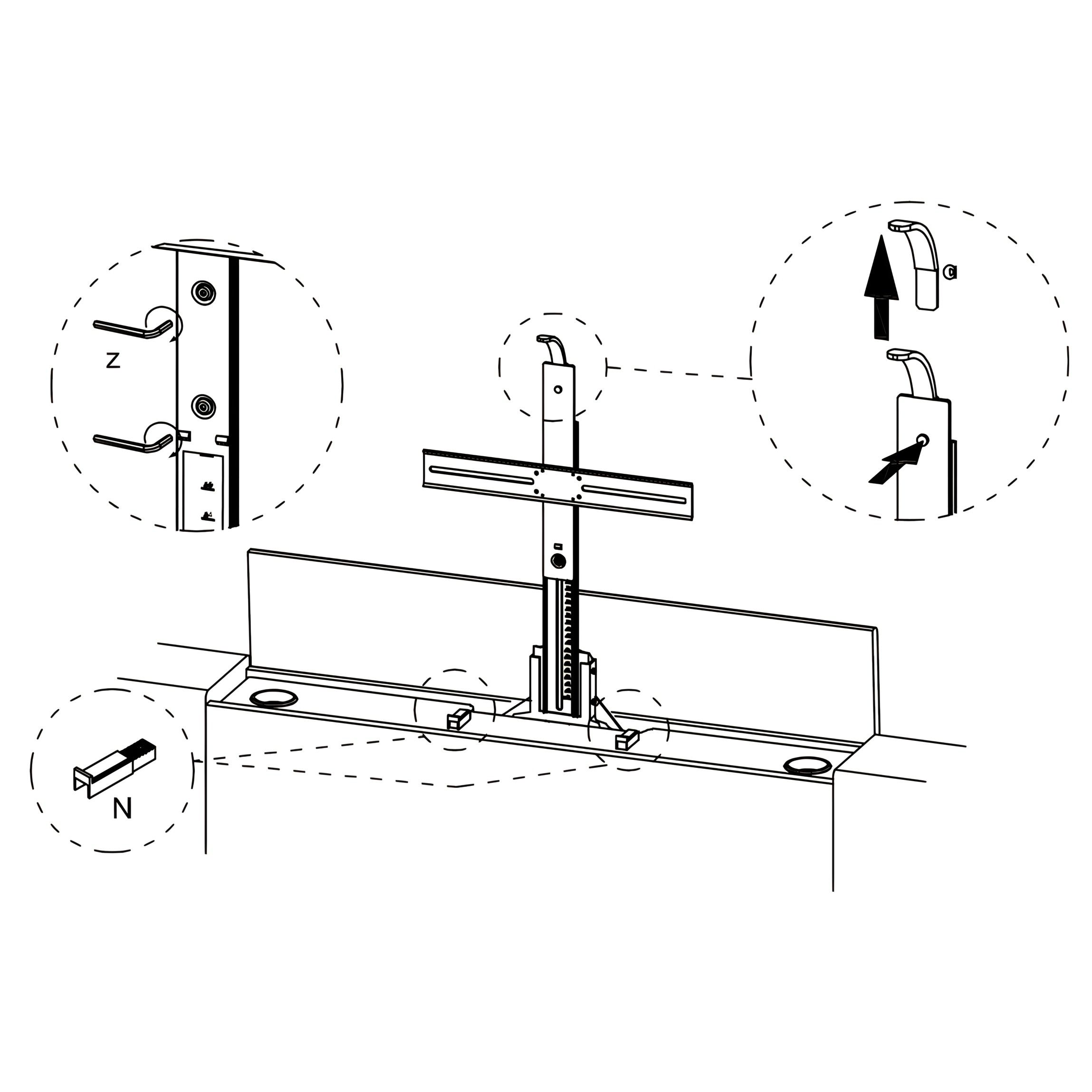
15. Fit the Television
1. Position your TV against the TV Support Slide (N). 2. Secure the TV brackets to the lift column using the supplied Allen Key (Z). 3. Ensure the brackets are tightened firmly and the TV is level.
Important: If hardware is supplied with your TV, please use it in preference to the fittings provided
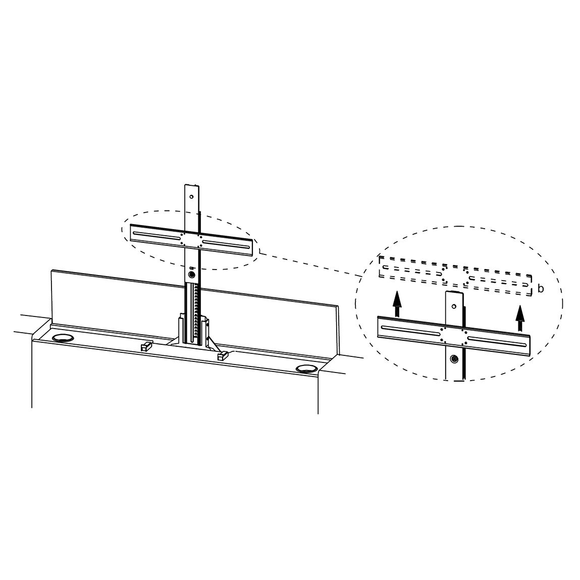
16. Adjust TV Support Bracket
1. Align the horizontal TV Support Bracket with the mounting holes on the lift column. 2. Adjust the bracket to the required height, depending on your TV size and mounting position. 3. Secure the bracket firmly with the supplied bolts.
Tip: Double-check that the bracket is level before tightening fully to ensure your TV sits straight.
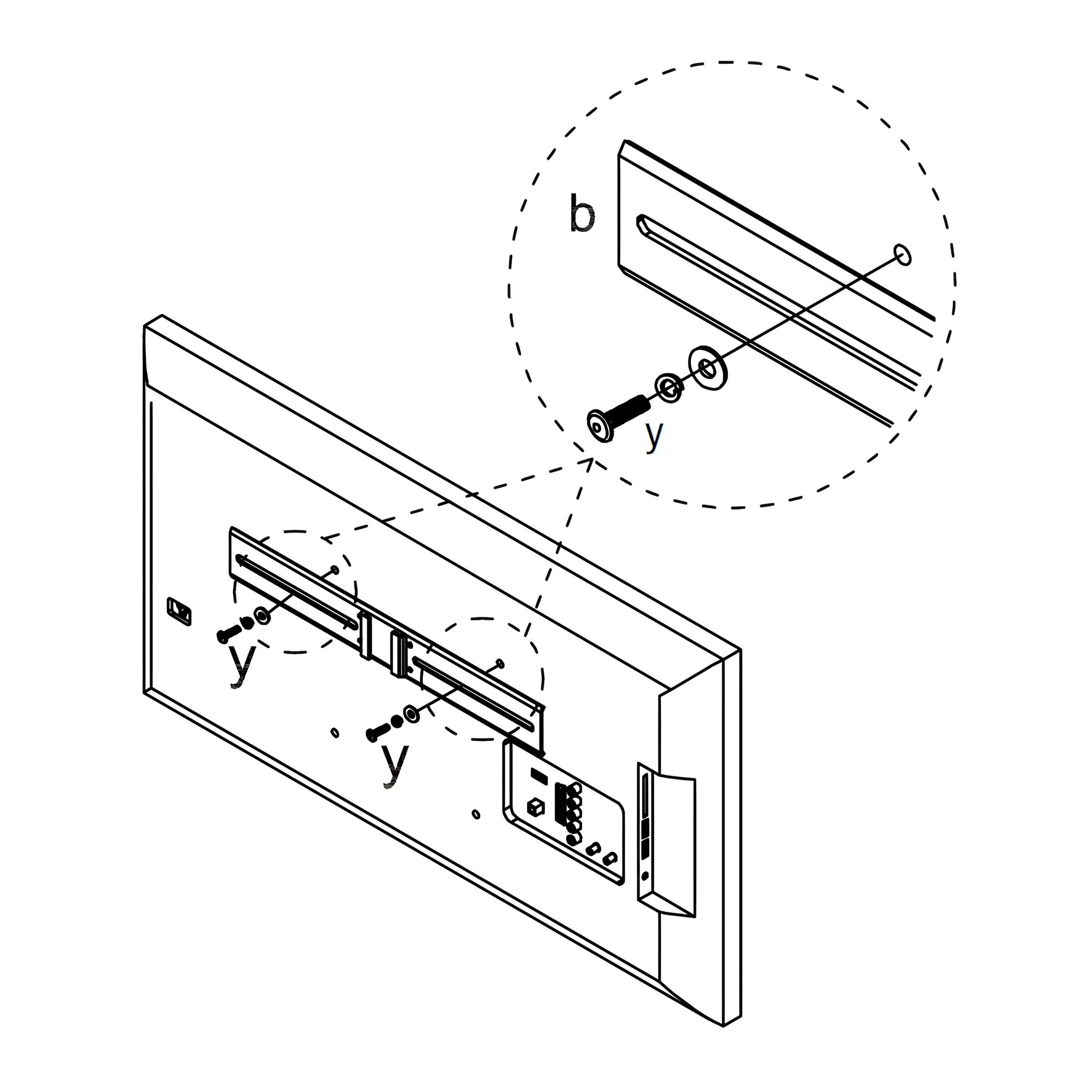
17. Attach TV Mounting Rails
1. On the back of your TV, position the Mounting Rails (b) so that the distance from each side is equal (X = Y). 2. Select the correct fittings from the TV Kit (y), or use the hardware supplied with your TV if available. Bolt sets (M8 × 25mm) Countersunk screw sets (M6 × 12mm) * Countersunk screw sets (M4 × 12mm) 3. Secure the rails to the TV using the chosen screws and the Allen Keys (Z).
Important: Always use the hardware supplied with your TV in preference. If not supplied, use the suitable fittings from the kit provided.
18. Mount TV onto Lift Bracket
1. Lift the TV and align the attached Mounting Rails (b) with the hooks on the TV Support Bracket. 2. Carefully lower the TV until the rails lock securely into place. 3. Check that the TV is sitting straight and firmly attached before releasing.
Tip: This step is easier with two people — one to hold the TV and the other to guide the rails onto the bracket.
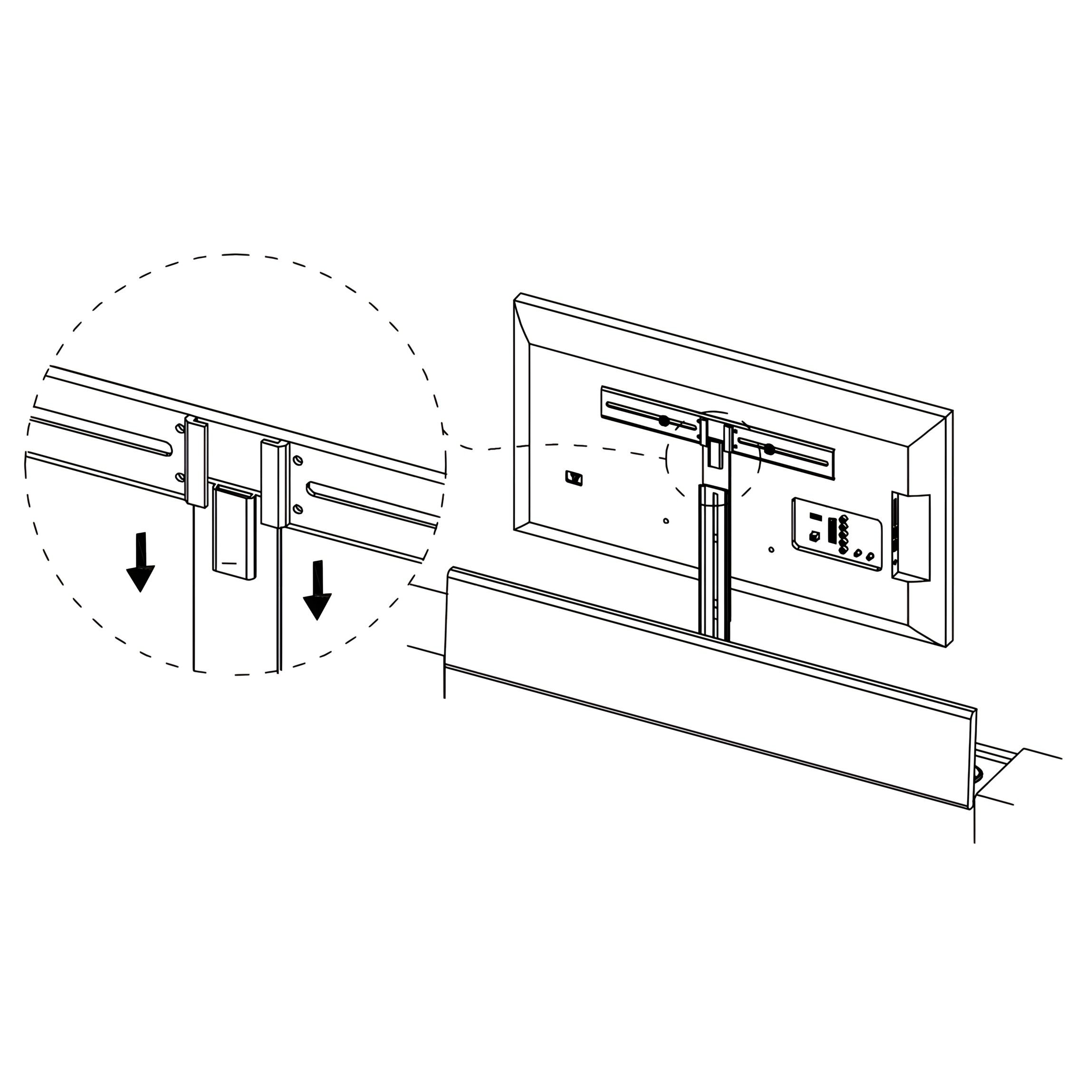
19. Secure TV with Locking Bar
1. Insert the Locking Bar into the slot at the top of the TV Support Bracket. 2. Push the bar down fully until it locks into place. 3. Ensure the bar is firmly seated to prevent the TV from lifting off the bracket.
Tip: Give the TV a gentle upward pull to confirm it is securely locked before continuing.
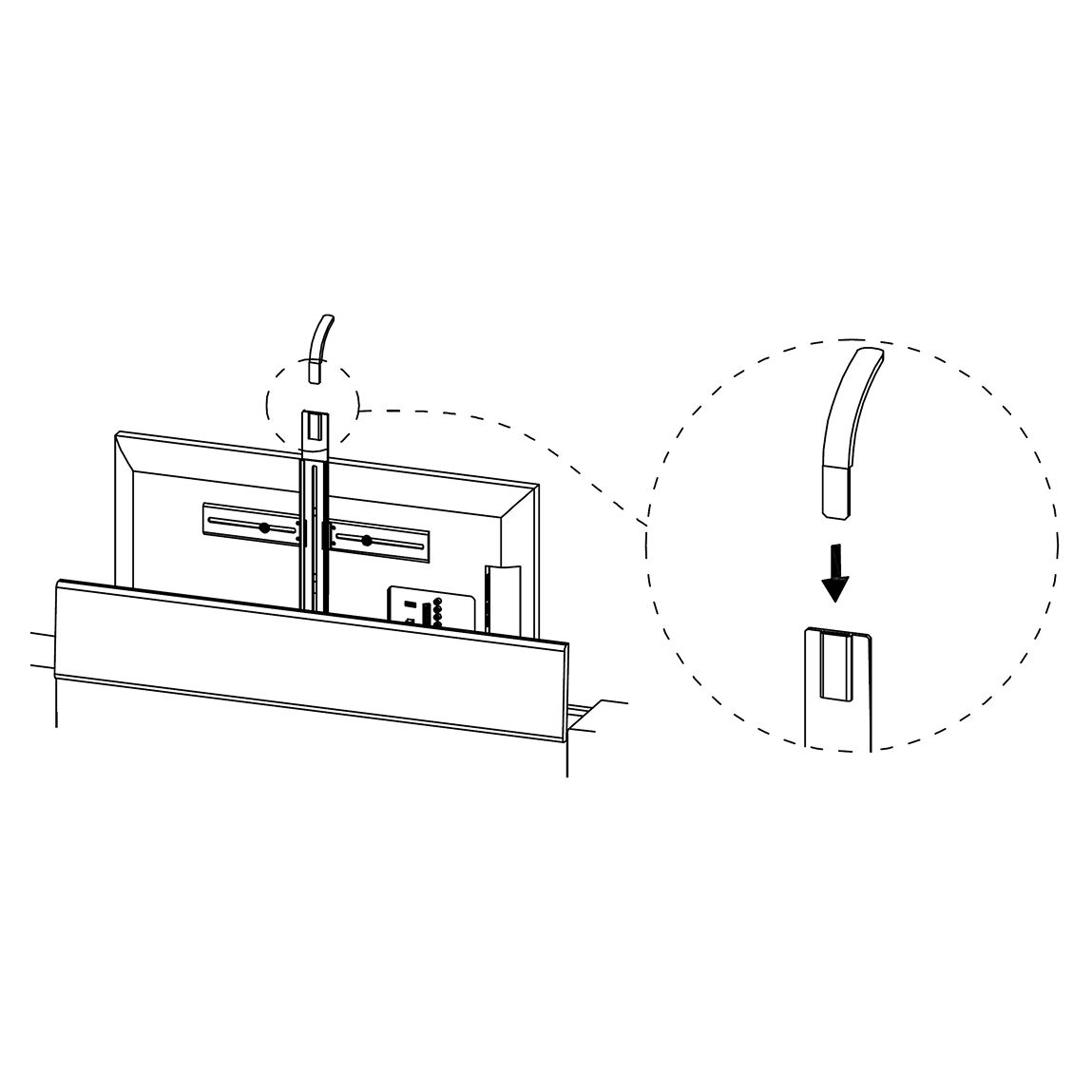
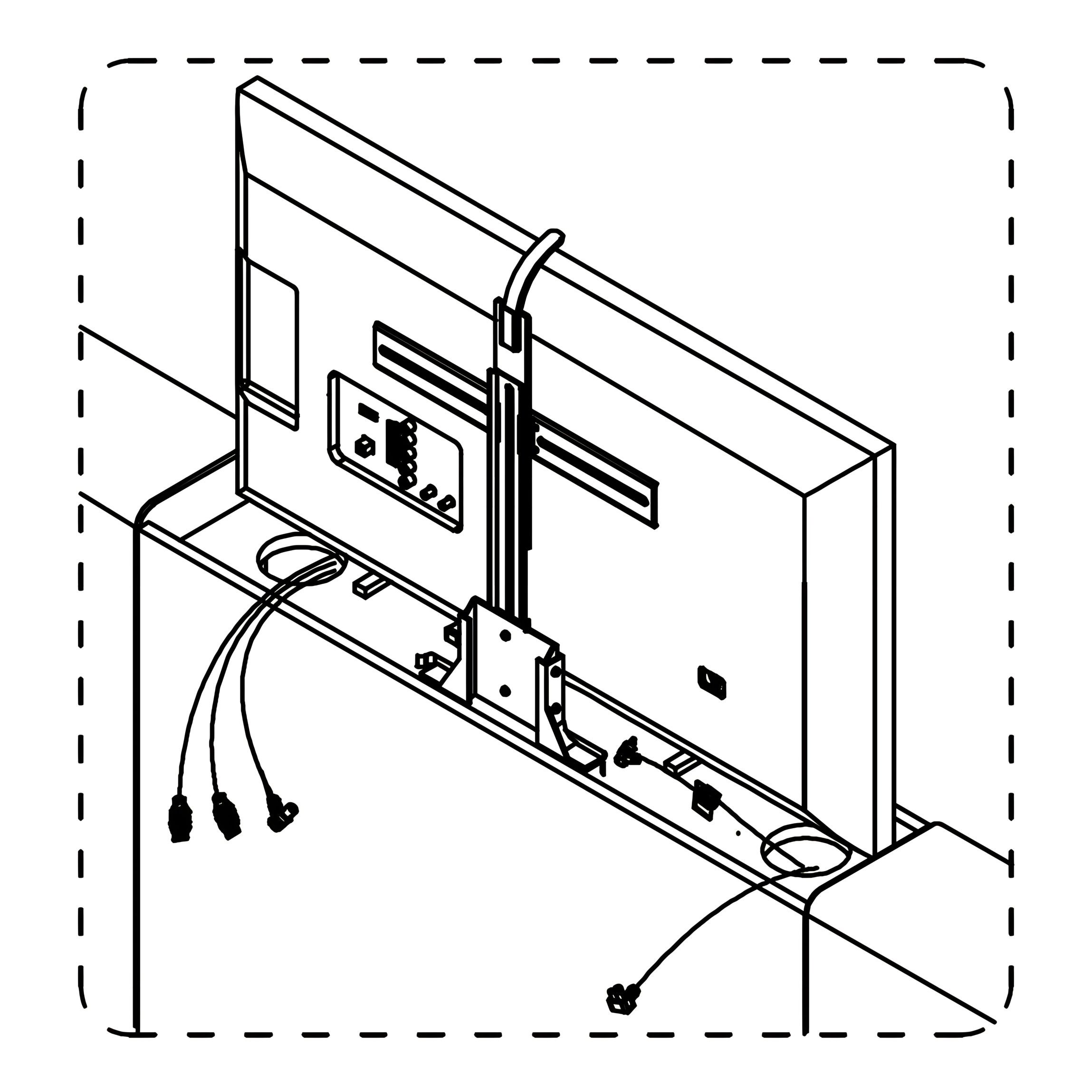
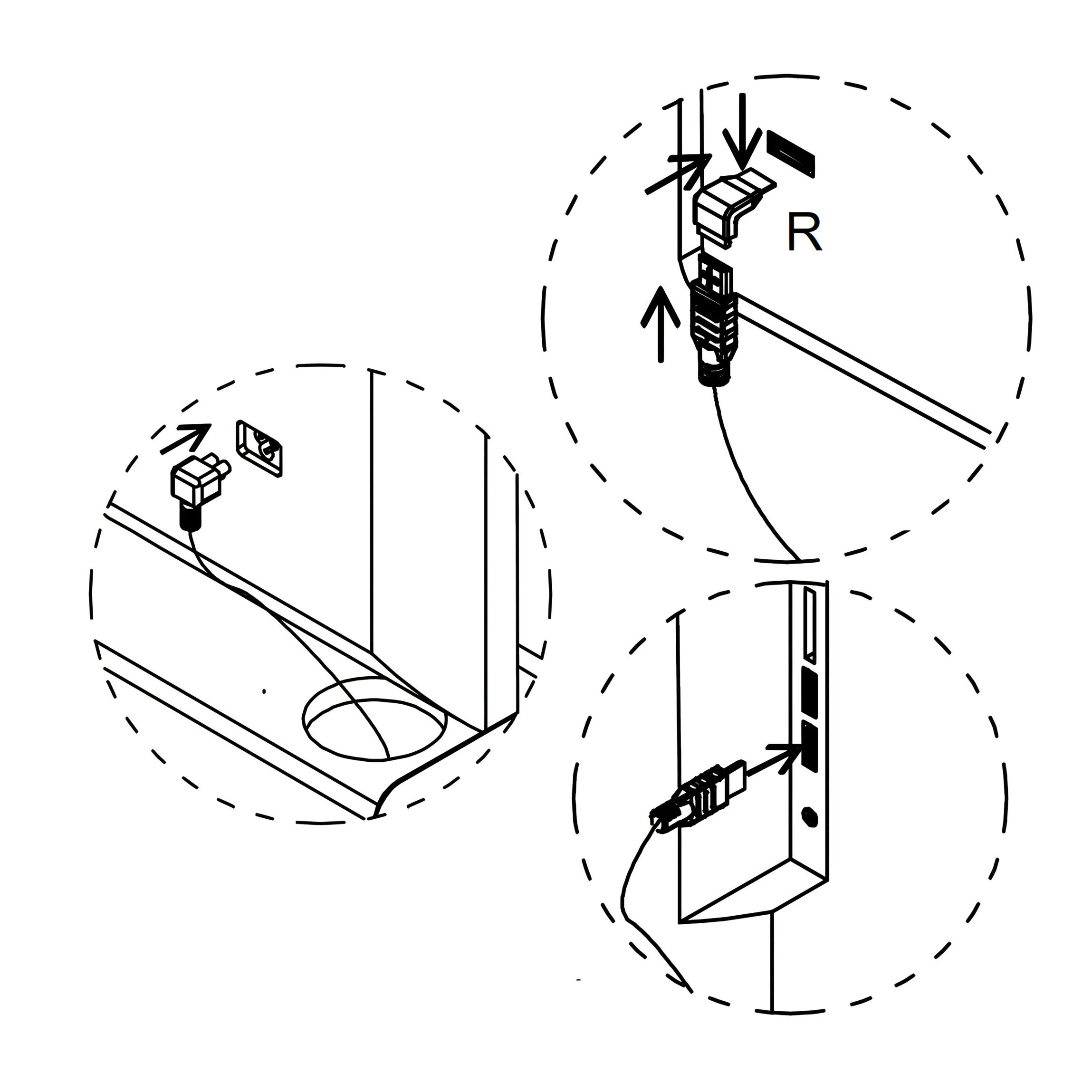
20. Connect and Secure TV Cables
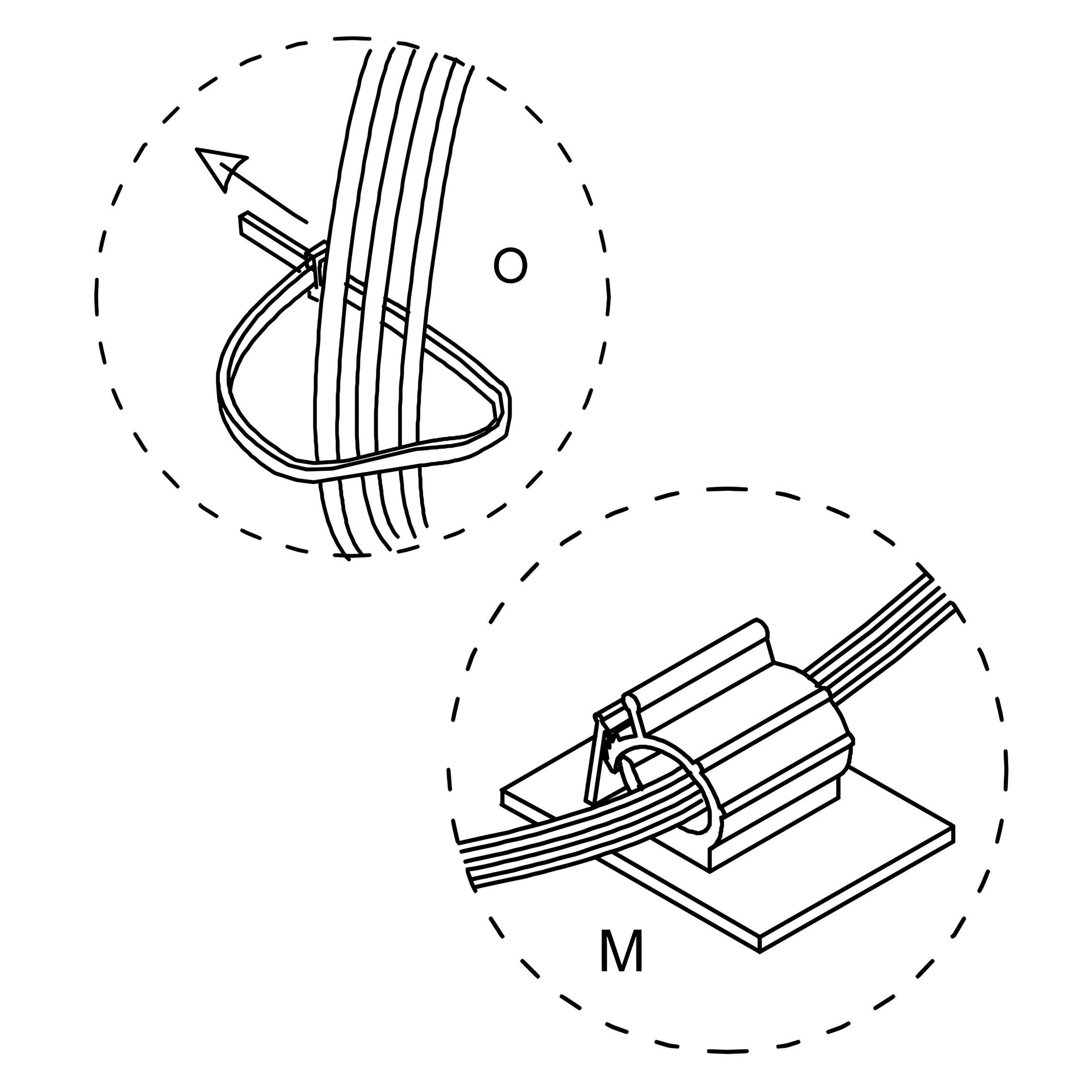
1. Plug the TV Power Lead (supplied with your TV) into the socket inside the Footboard (2). 2. Connect your HDMI Leads and Aerial Lead as required. Use the 90° HDMI Adapter (R) if needed for clearance. 3. Route the cables neatly through the ducts, ensuring they are not crossed. 4. Secure the cables to the back of the TV using the Cable Clips (M). 5. Use the Cable Ties (O) to bundle cables together and keep them tight.
Note: For illustration purposes only, TV connections may vary.
Tip: Keep all wires tight and well-organised to prevent interference with the lift mechanism.
21. Power and Lower the TV Lift
1. Plug in the TV Power Lead (supplied with your TV) to the socket inside the Footboard (2). 2. If required, connect the Aerial Lead to the wall socket. 3. On the Remote Control (P), press the “DOWN” button to lower the TV lift back into the footboard.
Note: Ensure all cables are connected securely and routed neatly before lowering the lift.
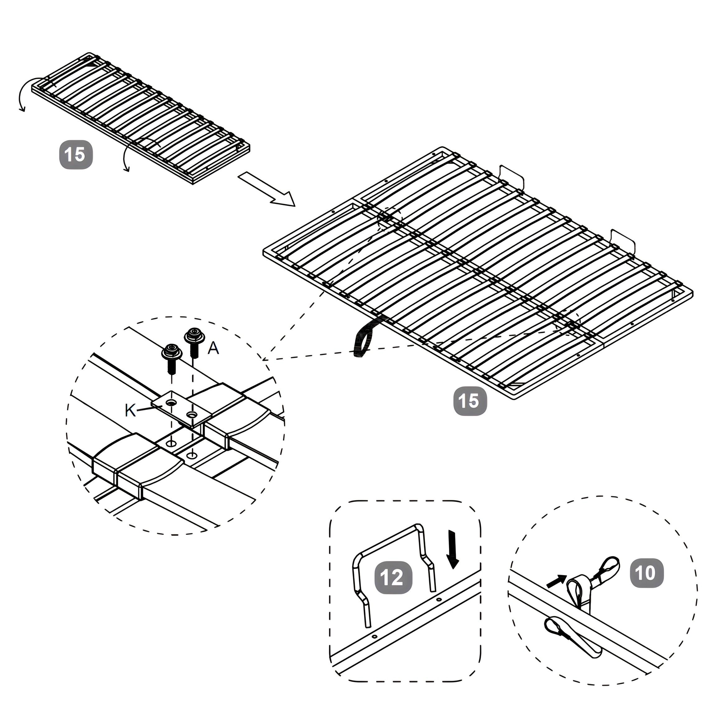
22. Assemble and Prepare Slat Frame
1. Join the two halves of the Metal Slat Frame (15) using the Metal Connection Plates (K). 2. Secure the plates with Bolts (A), tightening them with the Allen Key (I). 3. Insert the Mattress Stoppers (12) into the pre-drilled holes at the head of the frame. 4. Attach the Fabric Handle Strap (10) securely to the centre of the frame.
Tip: Ensure the slat frame is fully aligned before tightening all bolts.
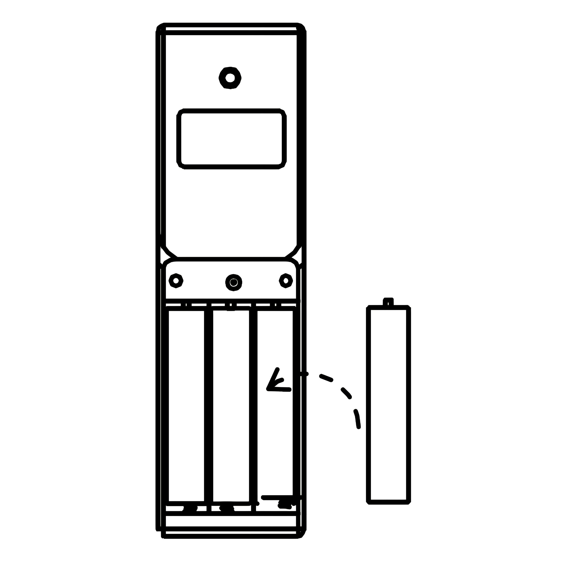
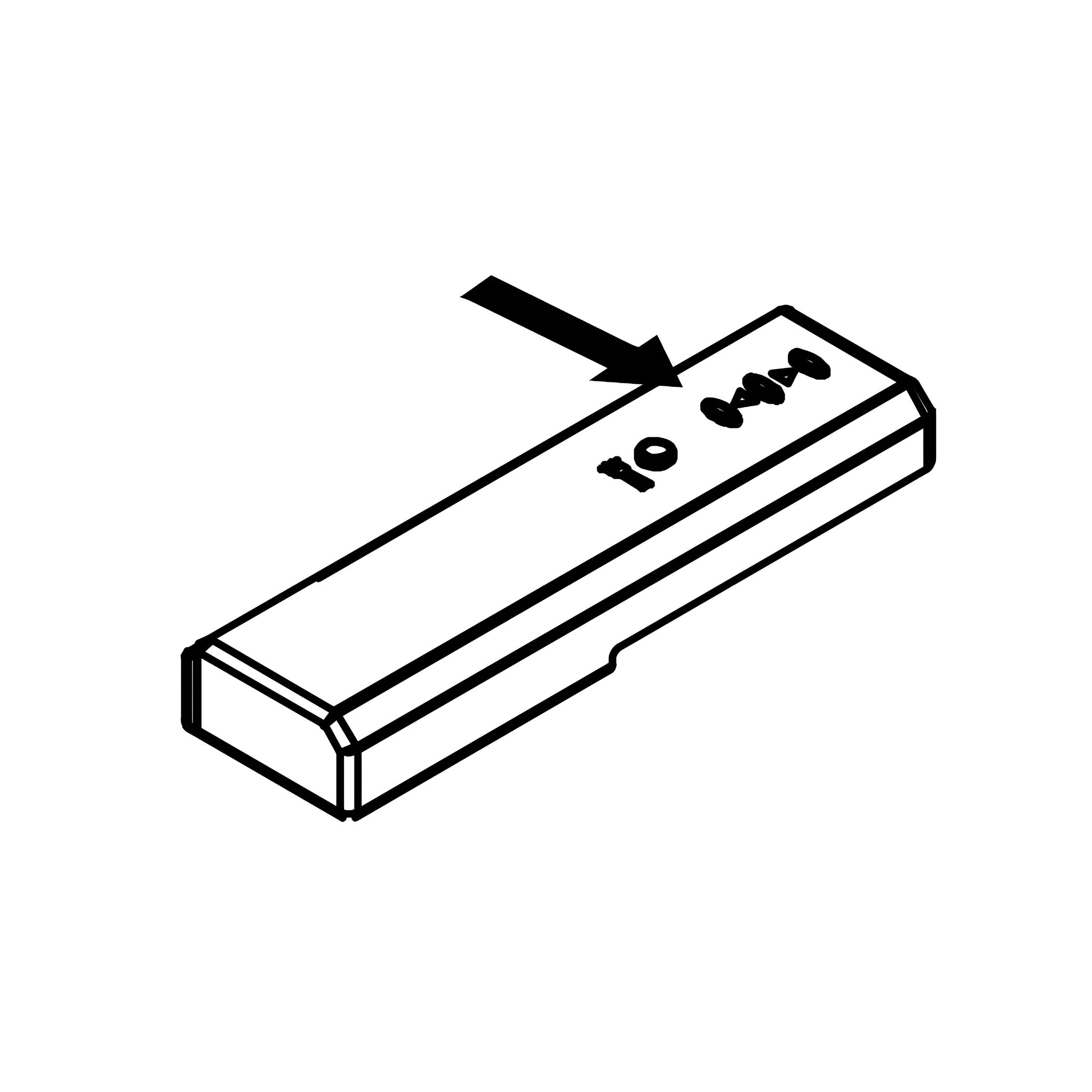
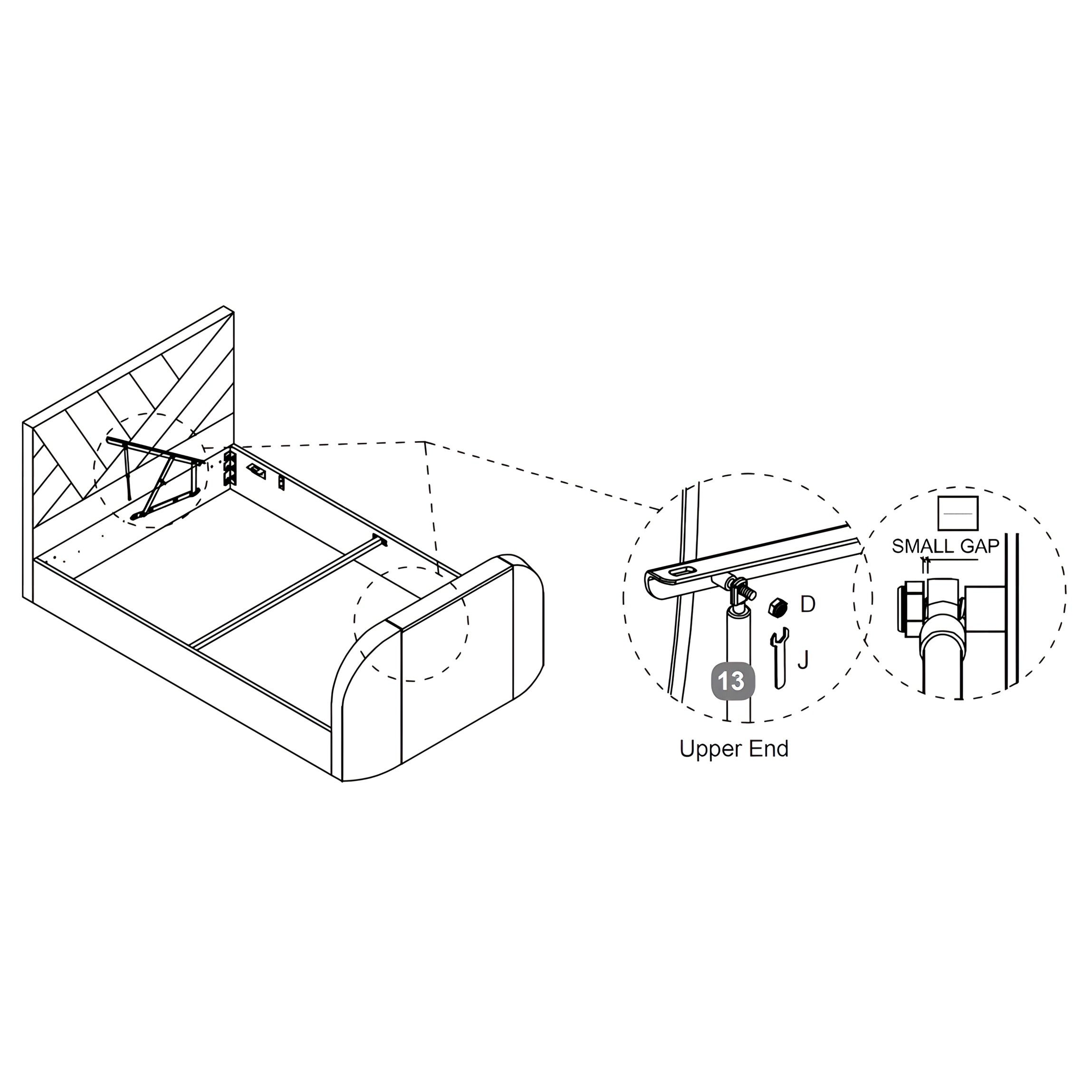
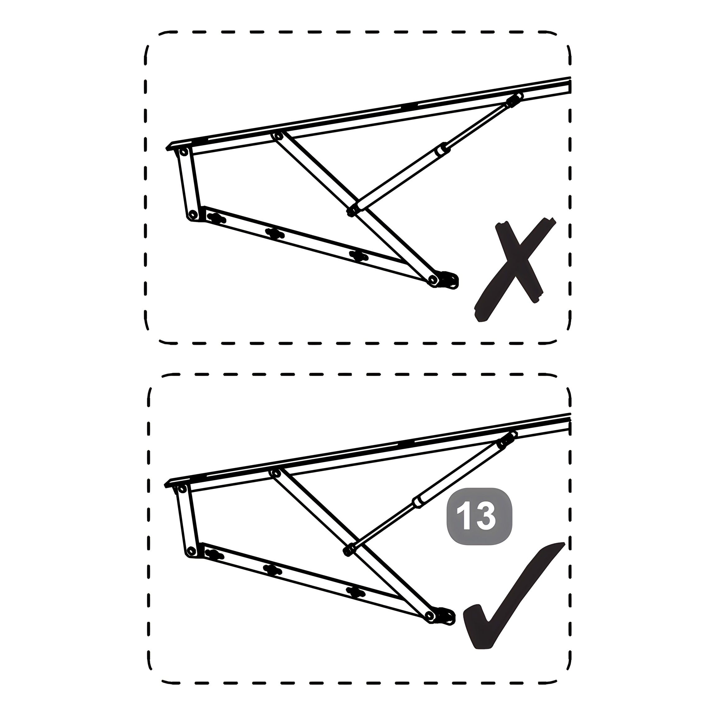
23. Install Gas-lift Pistons
1. Position each Gas-lift Piston (13) with the thinner end at the upper side of the mechanism (see diagram for correct orientation). 2. Slide the piston stem onto the axle of the Gas-lift Mechanism (5 & 6). 3. Secure in place using the Flanged Lock-Nuts (D), tightening with the Spanner (J). 4. Leave a small gap between the piston stem and the bracket to allow free movement.
Important: Ensure pistons are installed in the correct orientation. Installing them the wrong way will prevent the mechanism from functioning properly.
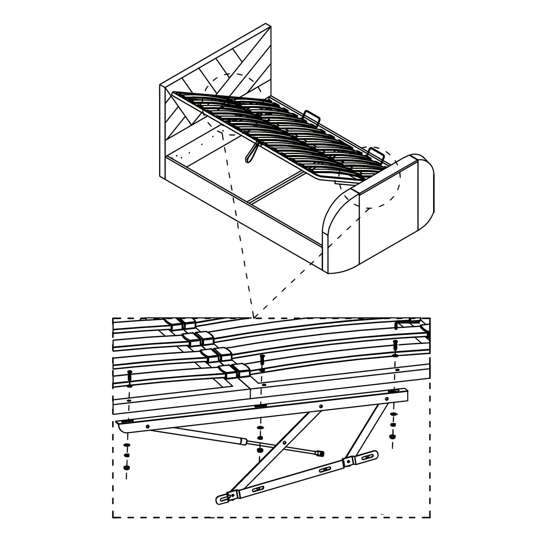
24. Secure the Metal Slat Frame
1. Lower the Metal Slat Frame (15) into position on top of the Gas-lift Mechanisms (5 & 6). 2. Align the holes on the slat frame with the brackets on the gas-lift arms. 3. Insert Bolt (C) with Flat Washer (F) and Spring Washer (E) through each hole. 4. Secure with a Flanged Lock-Nut (D) underneath, tightening with the Allen Key (I) and Spanner (J). 5. Ensure a small gap is left around the piston stem to allow smooth movement.
Tip: Tighten evenly across both sides to prevent frame misalignment.
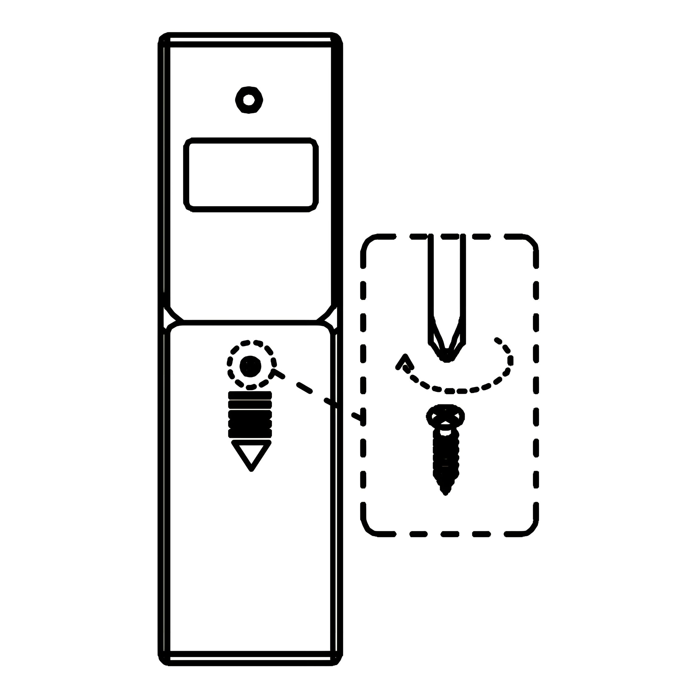
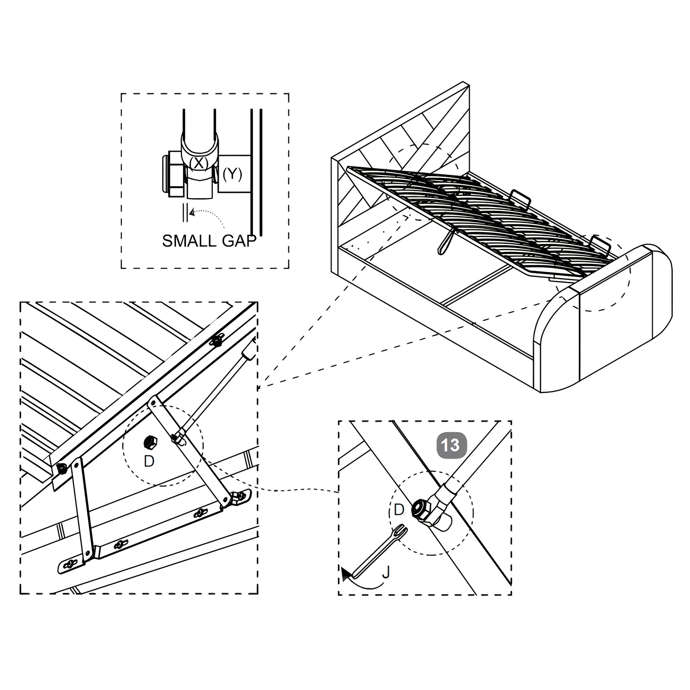
25. Gas-lift Piston Stem Adjustment and Testing
1. Slide the Gas-lift Piston Stem (13) onto the Axle (Y) located on the underside of the Metal Slat Frame (15). 2. Secure the piston in place with a Flanged Lock-Nut (D) using the Spanner (J). 3. Leave a small gap between the piston stem and the bracket (as shown) to allow free movement. 4. Repeat the process on the opposite side. 5. Carefully lift and lower the slat frame several times to check the gas-lift operation is smooth and secure.
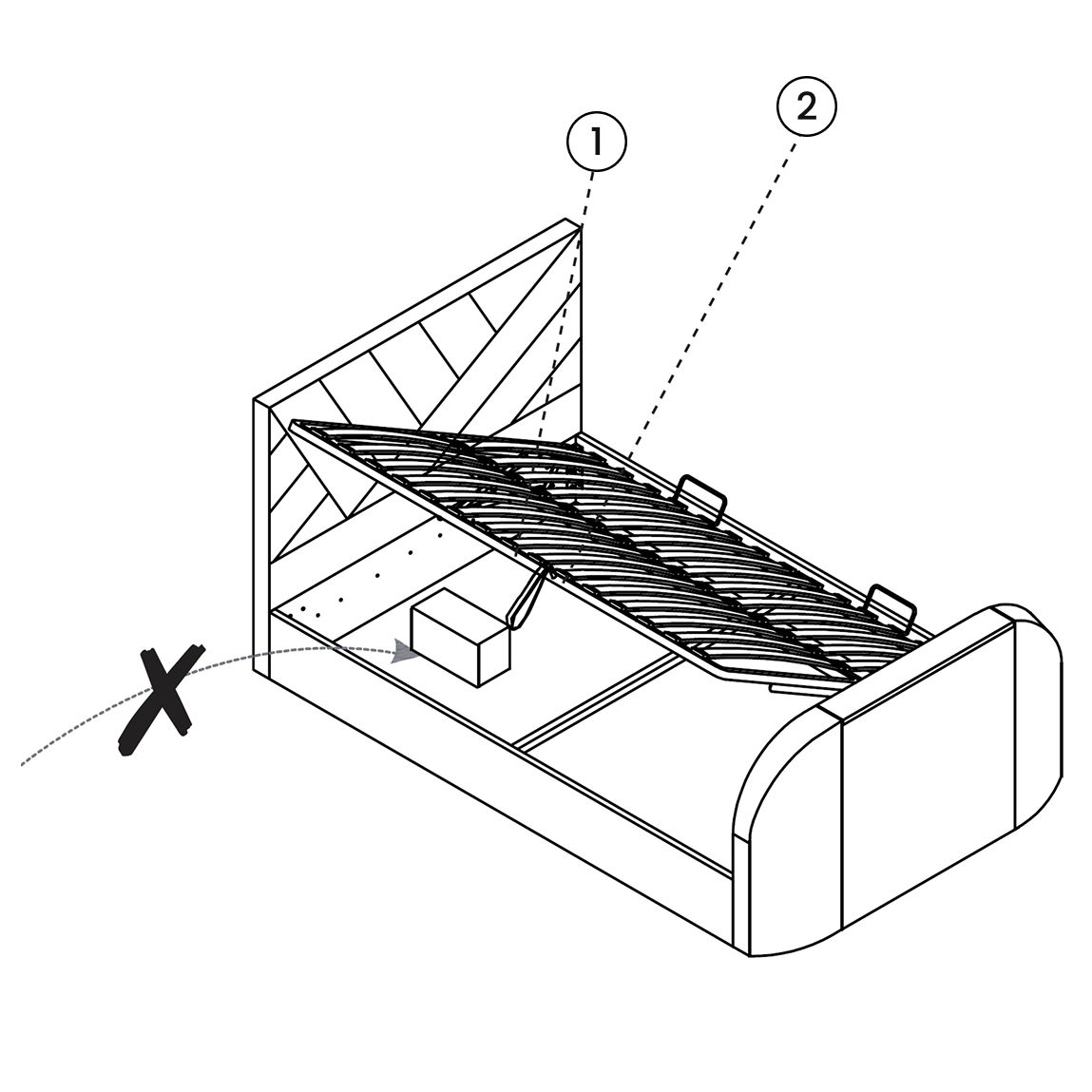
26. Final Checks and Safety Precautions
1. Storage Area Safety
Ensure the ottoman is fully open before accessing the storage space.
Avoid reaching through the hinge area to prevent injury.
Keep children and pets away from the bed when it is open.
Do not stand or climb inside the internal storage compartment.
Regularly inspect the bed mechanism to ensure it is functioning safely and smoothly.
2. Operating Instructions
The gas-lift mechanism is intended for adult use only. It is not suitable for users under 12 years old.
Always lift and lower the ottoman with the mattress in place, using the fabric hand strap (13) to raise and lower the base.
Keep hands and body clear of the lifting mechanism during operation to avoid entrapment.
Note: Be mindful of what you store under the bed. Items such as suitcases or boxes must not touch the underside of the slat frame, as this may cause damage.