Assembly instructions for Vancouver Winged Upholstered Ottoman TV Bed by Time4Sleep.
Product Information
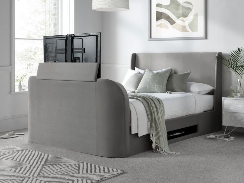
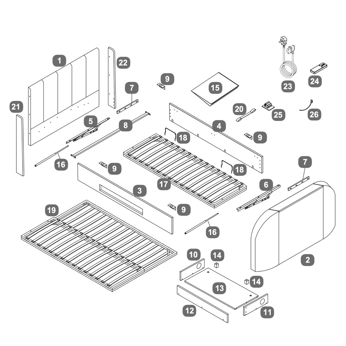
Vancouver Winged Upholstered Ottoman TV Bed
The Vancouver Ottoman Winged TV bed is the ideal choice for enjoying your favourite TV shows, movies, or video games from the comfort of your bed. With a remote-controlled TV lifting mechanism, this bed allows you to discreetly hide the TV when it's not in use. It can hold TVs up to 43 inches, with adjustable brackets to accommodate different sizes.
The Vancouver TV bed also features a subtle side storage box, perfect for storing your TV accessories and game consoles. Beautifully upholstered, the bed boasts a padded headboard with contemporary vertical stitching and a winged design, making it a versatile piece that fits well in both modern and traditional bedroom settings.
The bed includes a sprung slatted base that provides a comfortable foundation for your mattress. Additionally, the gas lift ottoman base can be easily raised from the side, revealing a 24cm deep storage compartment, offering a discreet solution for storing items.
The frame is designed to accommodate an LED flat-screen TV up to 43".
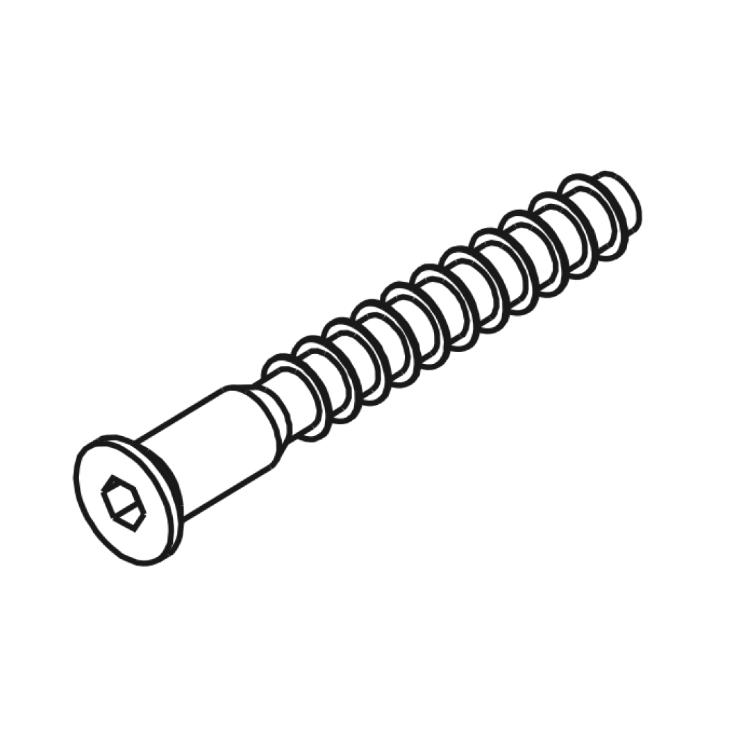
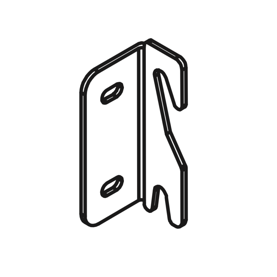
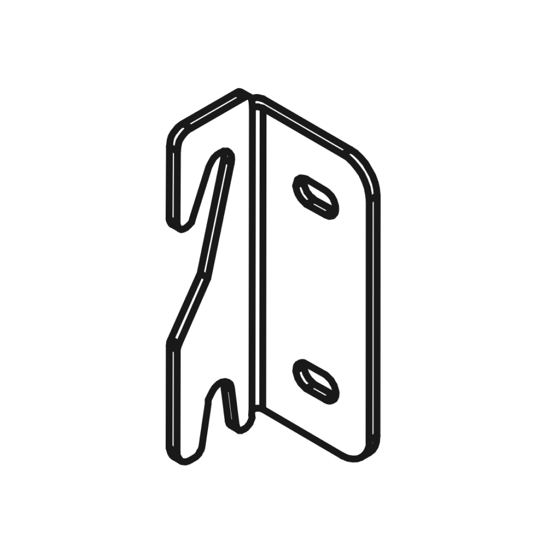
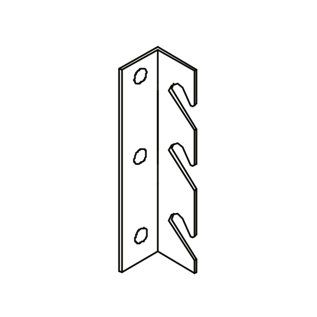
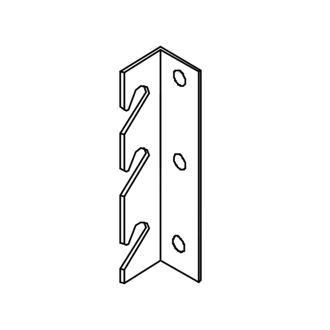
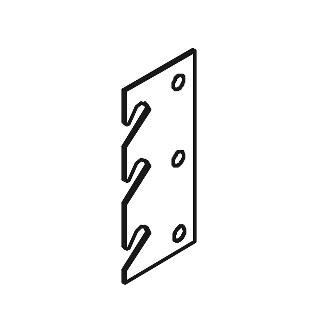
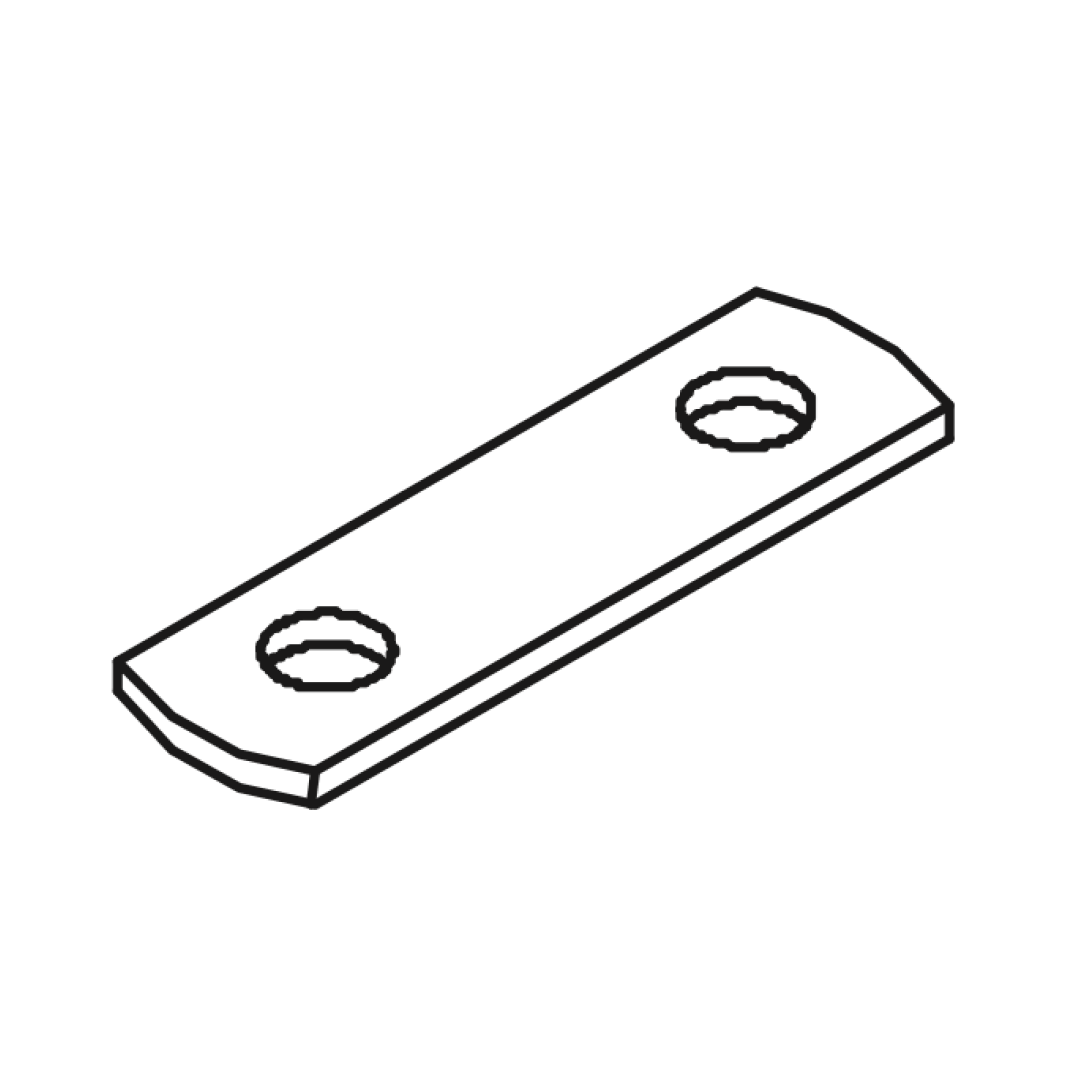
1. Attach the angle bracket (G) to the left side of the side rail with media tray, and a flat bracket (R) in the right side. 2. Attach the angle bracket (H) to the left side of the other side, and a flat bracket (R) in the left side. 3. Insert three bolts (A) through the holes of the brackets in each side rails.
Ensure all connections are tight before proceeding with the next steps of the assembly.
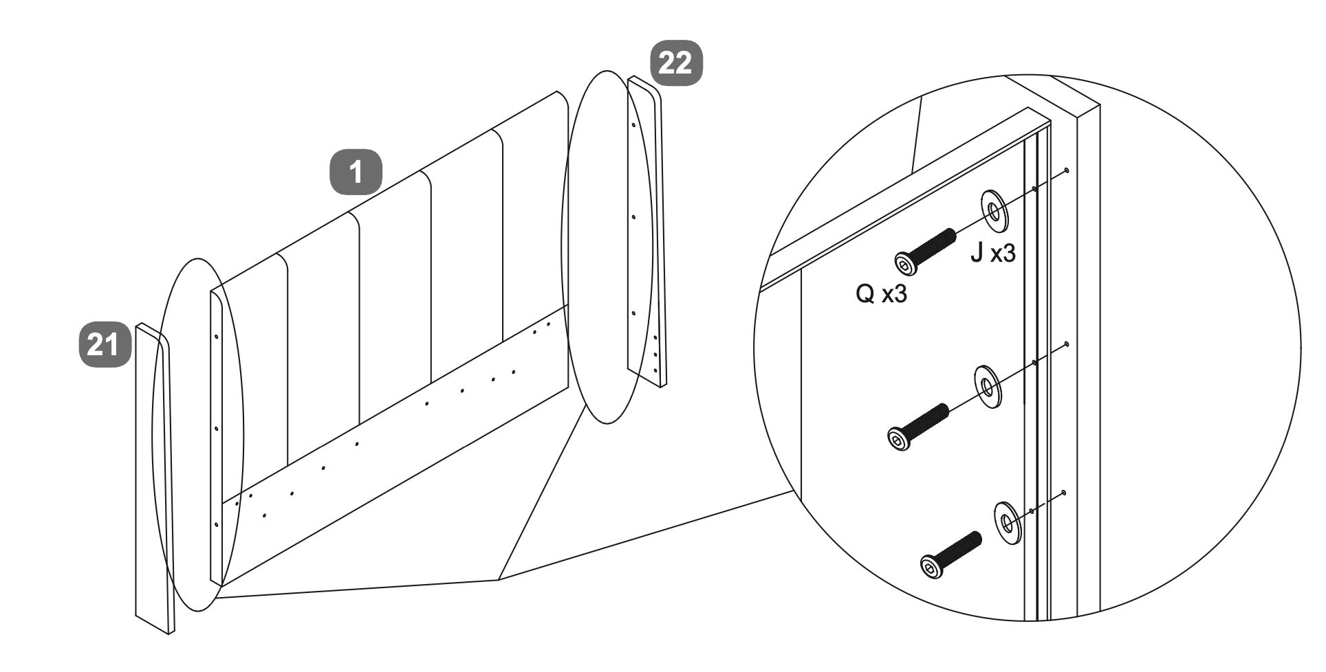
2. Headboard Wings
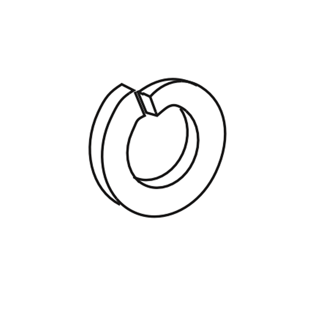
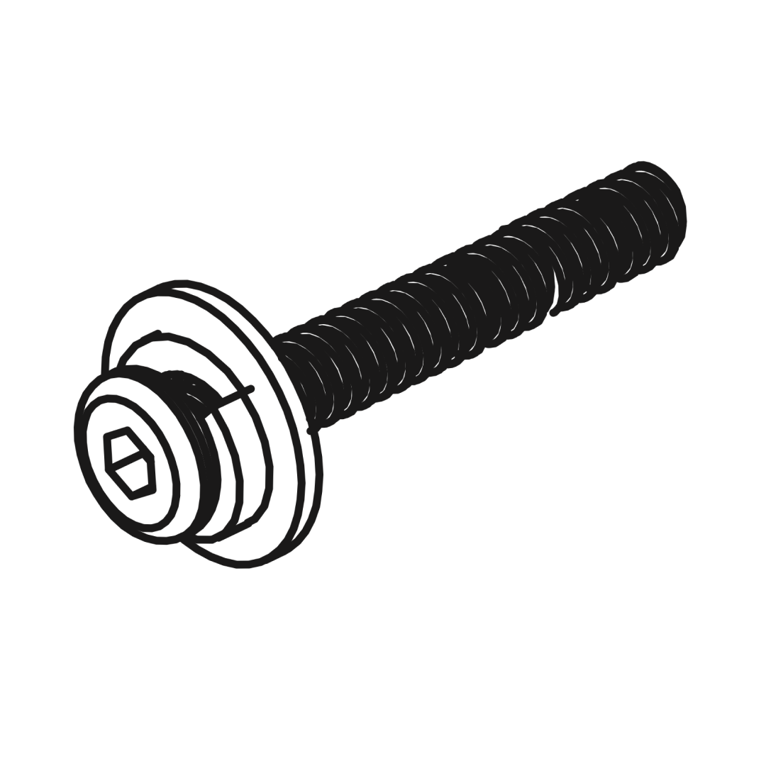
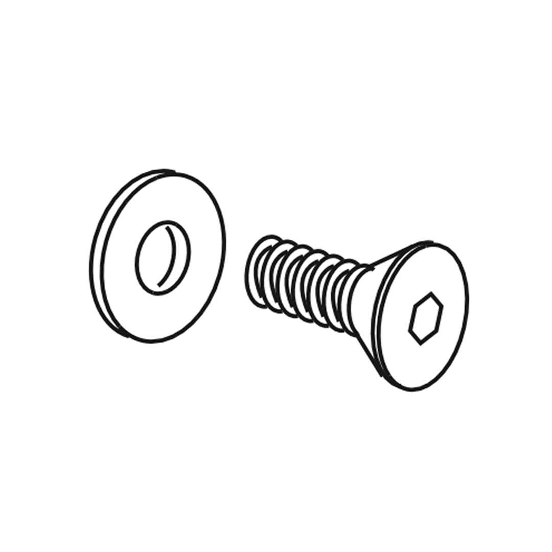
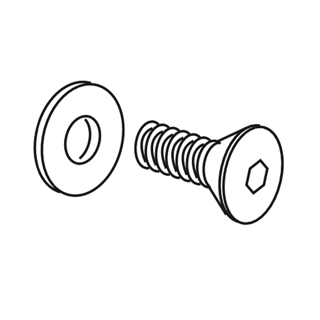
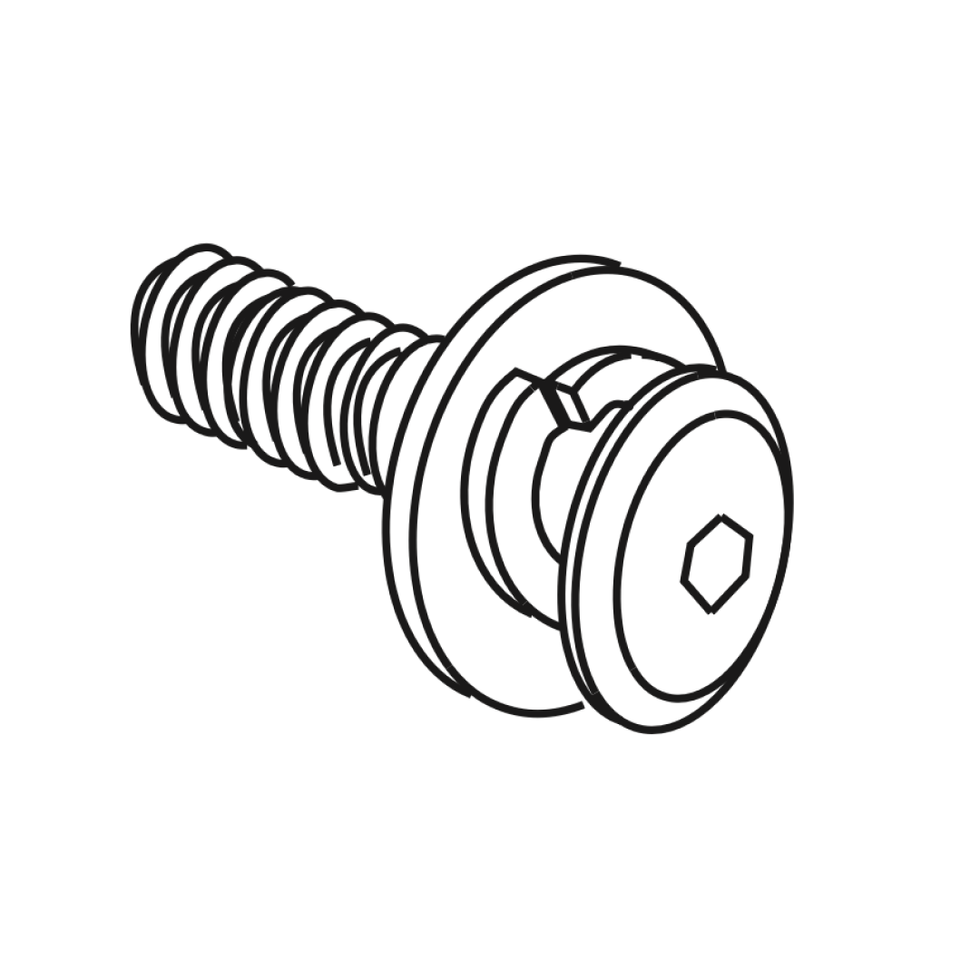
1. Align the headboard wings (21 and 22) with the main headboard piece (1). 2. Secure each side panel to the headboard using three bolts (Q) and washers (J) as shown in the detailed view. 3. Ensure all connections are tight and the panels are properly aligned with the headboard.
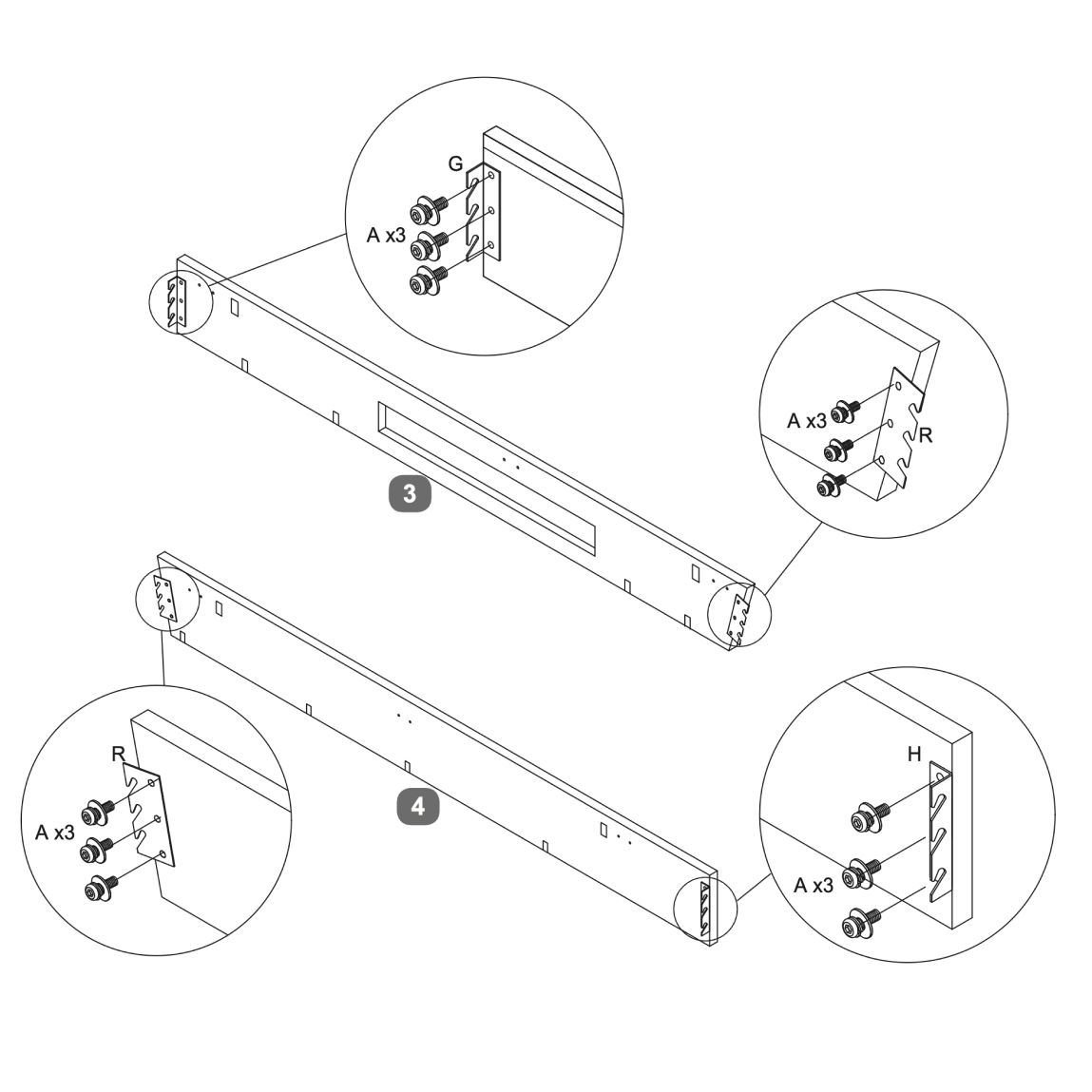
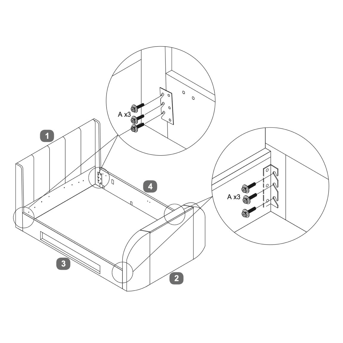
3. Headboard and footboard
1. Position the side rails to connect with the headboard and footboard. 2. Use 3 bolts (A) for each bracket, to secure the side rails to the headboard and footboard. Ensure all connections are tight. 3. Verify that all components are properly aligned and securely fastened.
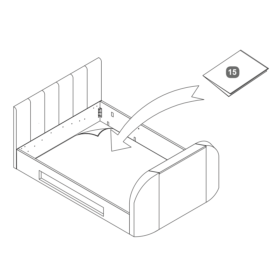
4. Fabric Base Cover
1. Position the fabric base cover (15) inside the bed frame. 2. Ensure it is aligned properly with the edges of the frame. 3. Secure the fabric base cover in place as per the assembly instructions provided with the bed.
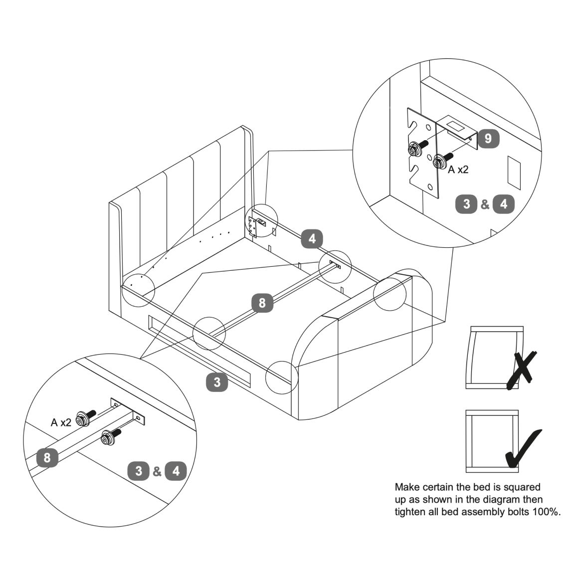
5. Cross Bar
1. Attach the ‘L’ shape brackets (9) to the side rails using bolts (A). Insert two bolts on each side, as indicated in the diagram. 2. Attach the cross bar to the side rails. Use bolts (A) to secure the connection. 3. Ensure all bolts are tightened 100% once the bed is properly squared. 4. Check that the headboard wings are properly aligned and secured.
6. Media Tray
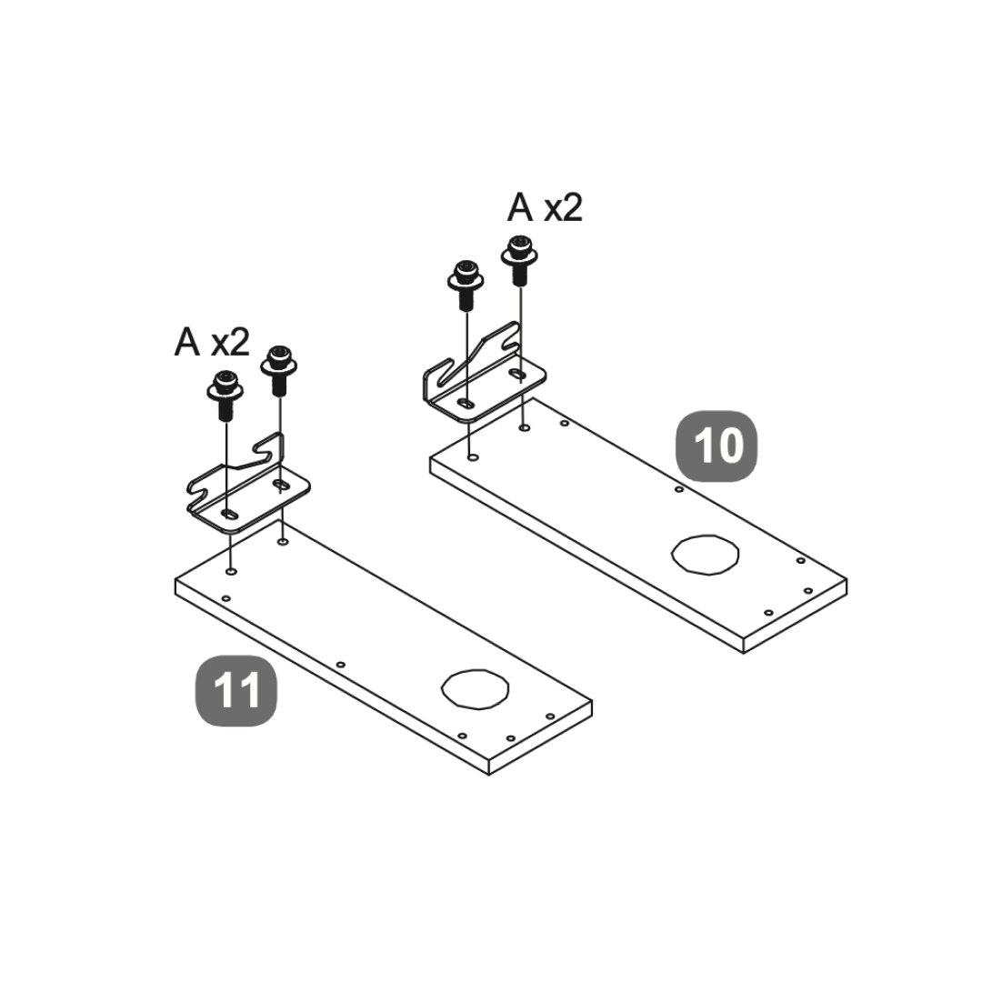
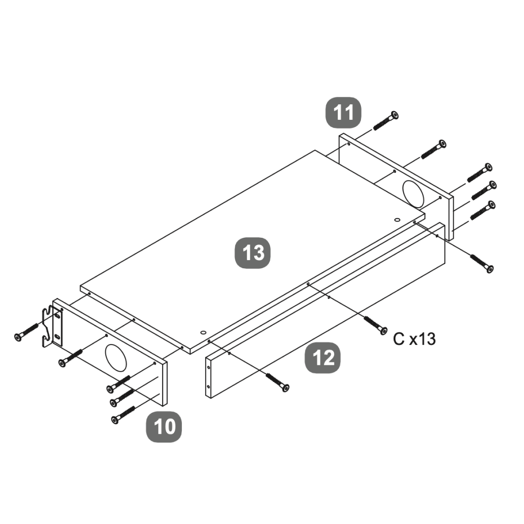
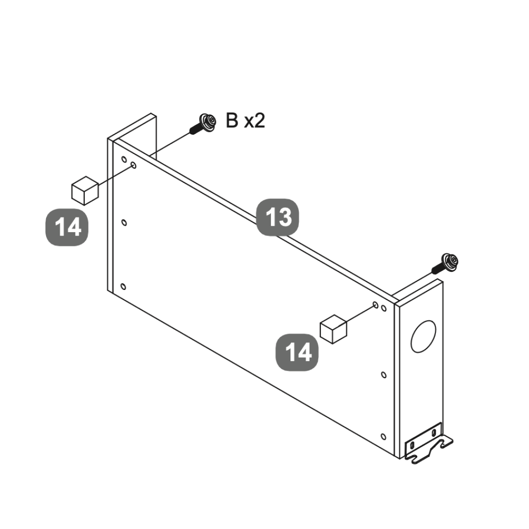
1. Secure two brackets (A) to each of the side panels (10 and 11) using the provided screws and nuts. 2. Connect panels 10 and 11 to the side panel 12 using screws (C x13). 3. Attach the base panel 13 to the assembled frame, aligning it with the pre-drilled holes and securing it with screws. 4. Attach support legs (14) to the panel 13 using screws (B x2). 5. Ensure all components are securely fastened and aligned properly before proceeding with further assembly or installation.
7. Attach Media Tray
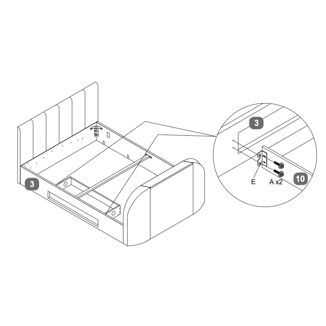
1. Secure the media tray to the corresponding side using bolts (A) provided 2. Ensure all components are tightly fastened and properly aligned
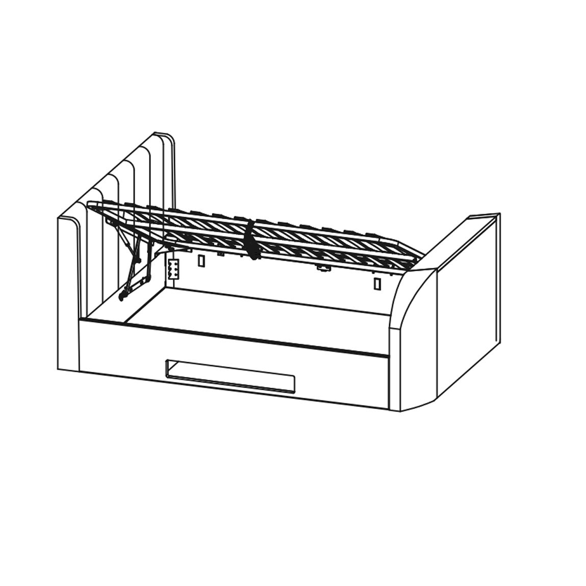
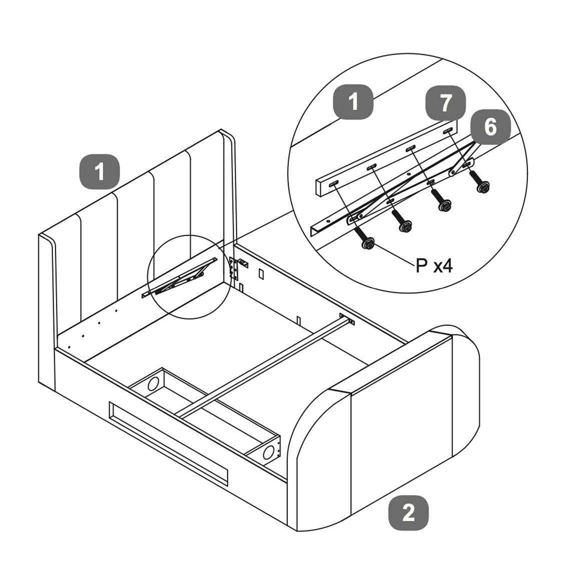
8. Lift Mechanism - Open from Left
To open the bed from the left:
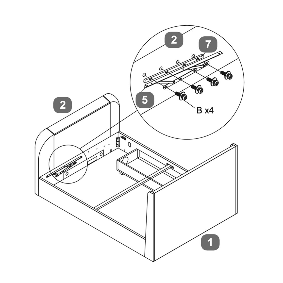
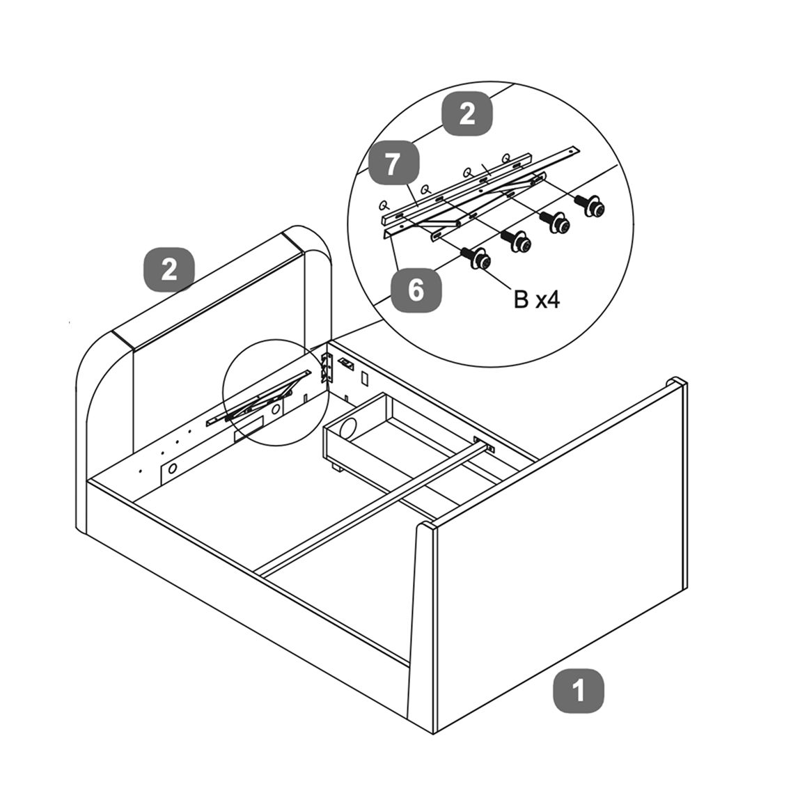
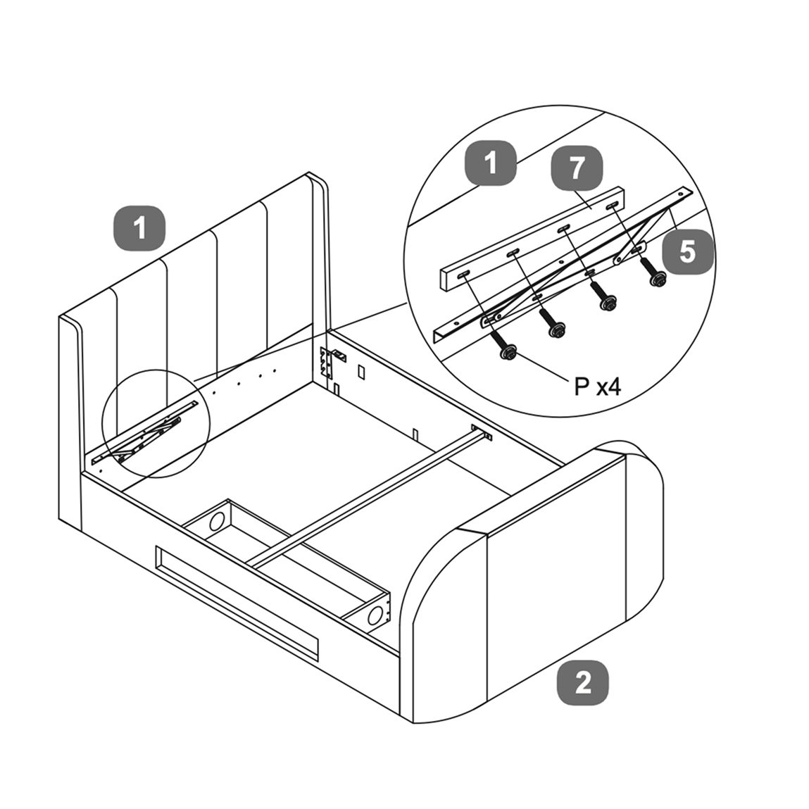
1. Position the gas lift mechanism (6) and the spacer rails (7) on headboard . 2. Ensure the mechanism is aligned properly with the pre-drilled holes. 3. Use the provided bolts (P x4) to secure the mechanism to the side rails, as illustrated in the second image. 4. Tighten the bolts to ensure stability. 5. Repeat the process on the footboard using bolts (B x4) as shown in the third image. 6. Ensure both sides are securely fastened and aligned.
9. Lift Mechanism - Open from Right
To open the bed from the right:
1. Position the gas lift mechanism (6) and the spacer rails (7) on headboard . 2. Ensure the mechanism is aligned properly with the pre-drilled holes. 3. Use the provided bolts (P x4) to secure the mechanism to the side rails, as illustrated in the second image. 4. Tighten the bolts to ensure stability. 5. Repeat the process on the footboard using bolts (B x4) as shown in the third image. 6. Ensure both sides are securely fastened and aligned.
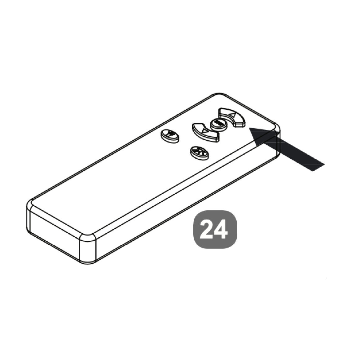
10. TV Lift Power Cable
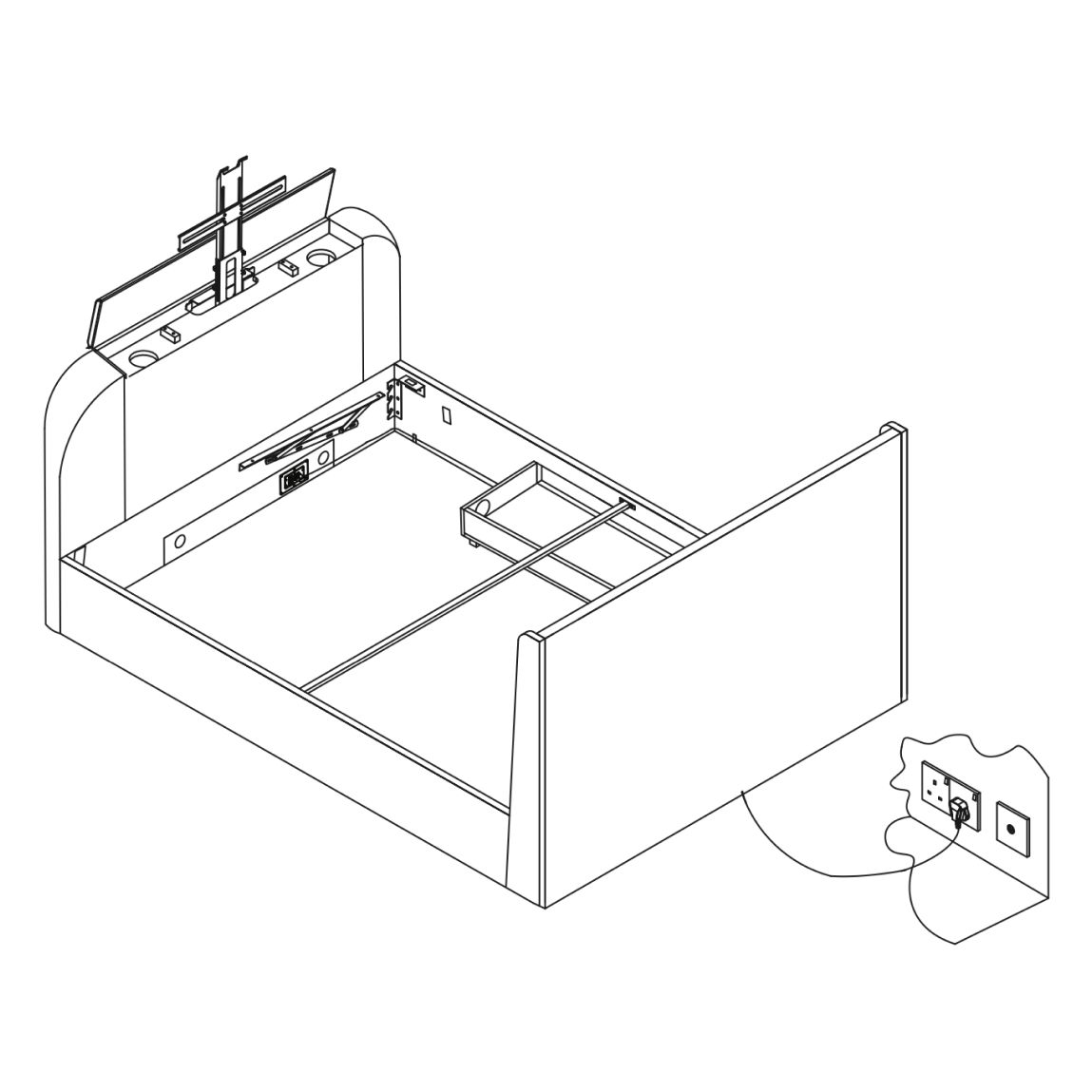
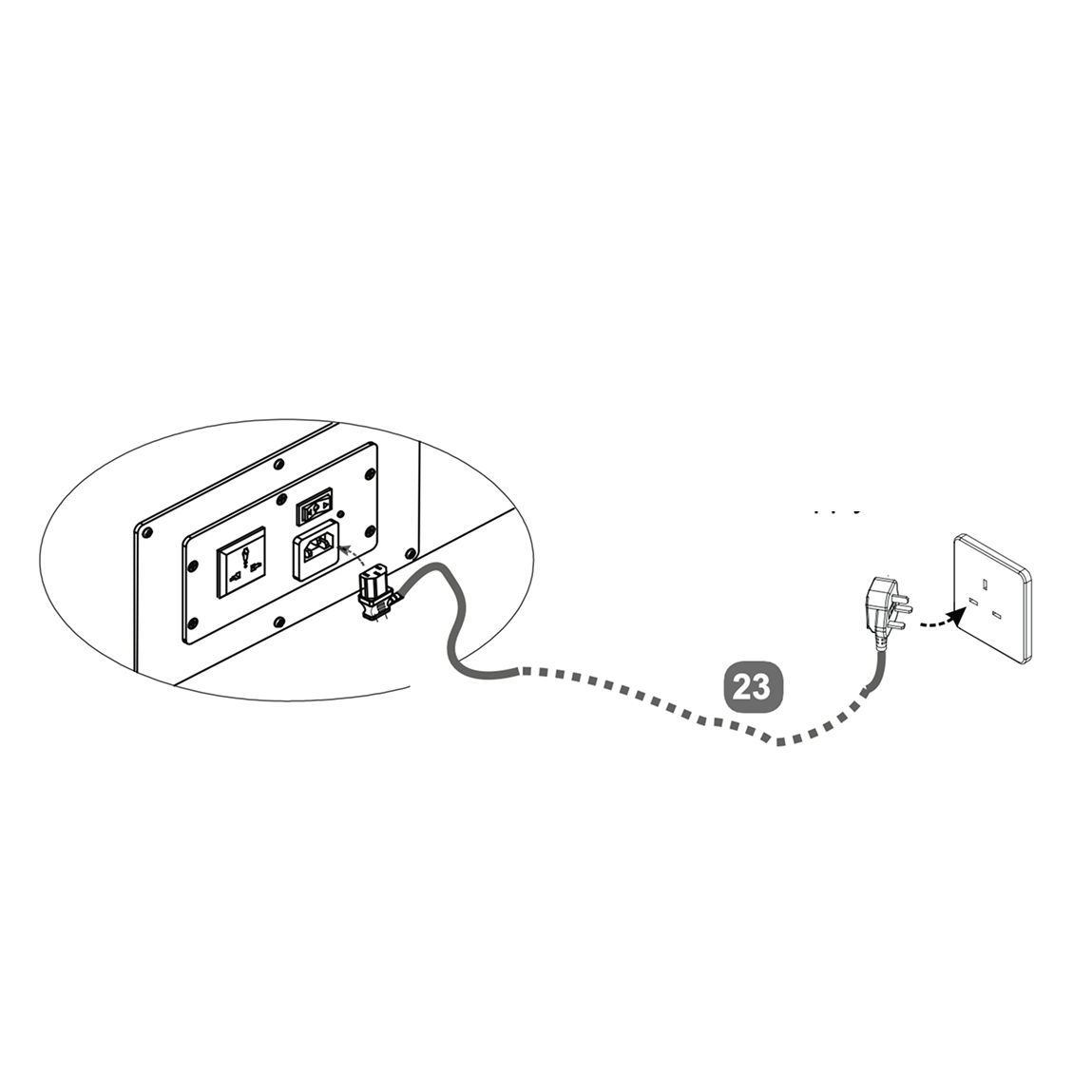
1. Attach the power cable to the TV lift mechanism at the headboard. 2. Connect the power cable to the nearest electrical outlet - for safety, this must be an earthed supply. 3. Use the handheld remote control to operate the TV lift. Press the “UP” button to raise the TV lift.
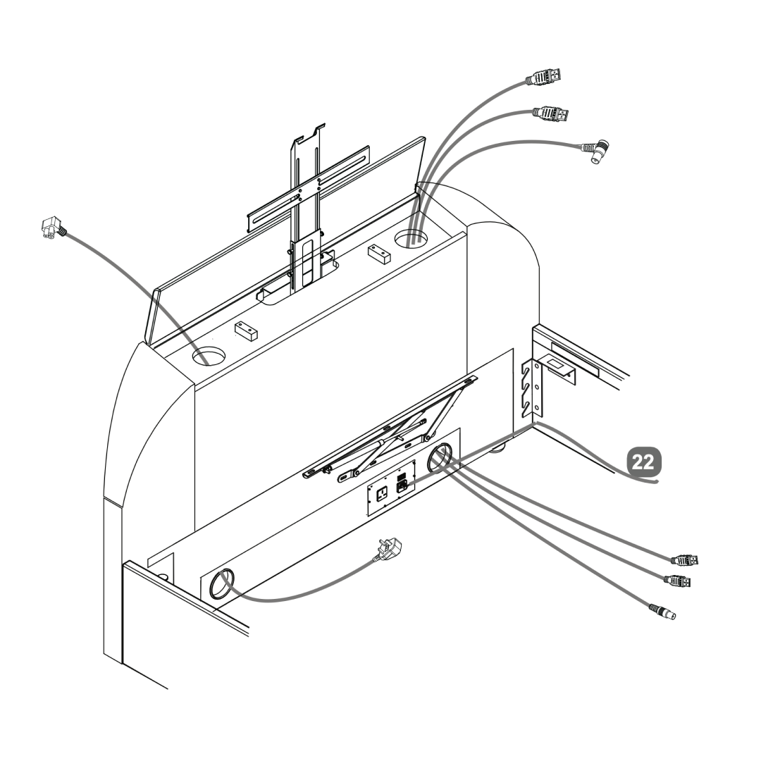
11. Media Cables
Pass the TV power and media cables through the side holes of the footboard.
For illustration only, cables should be fitted to suit the positions of the ports in your own TV.
Media cables are not supplied.
Tip:
Before fitting the television, push any leads through each duct from the top.
Choose the best side to use depending on where the connection ports are on back of your tv. Never cross cables from one side to the other.
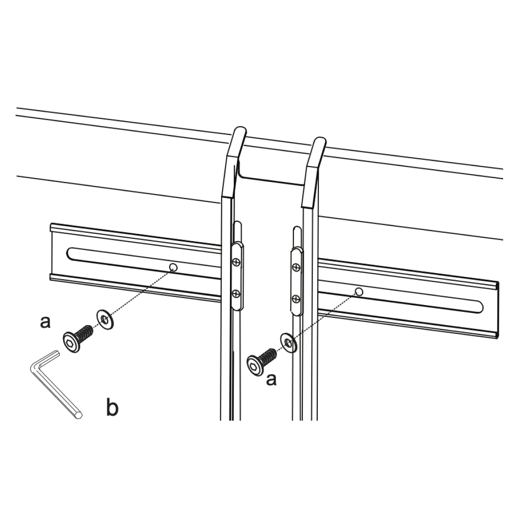
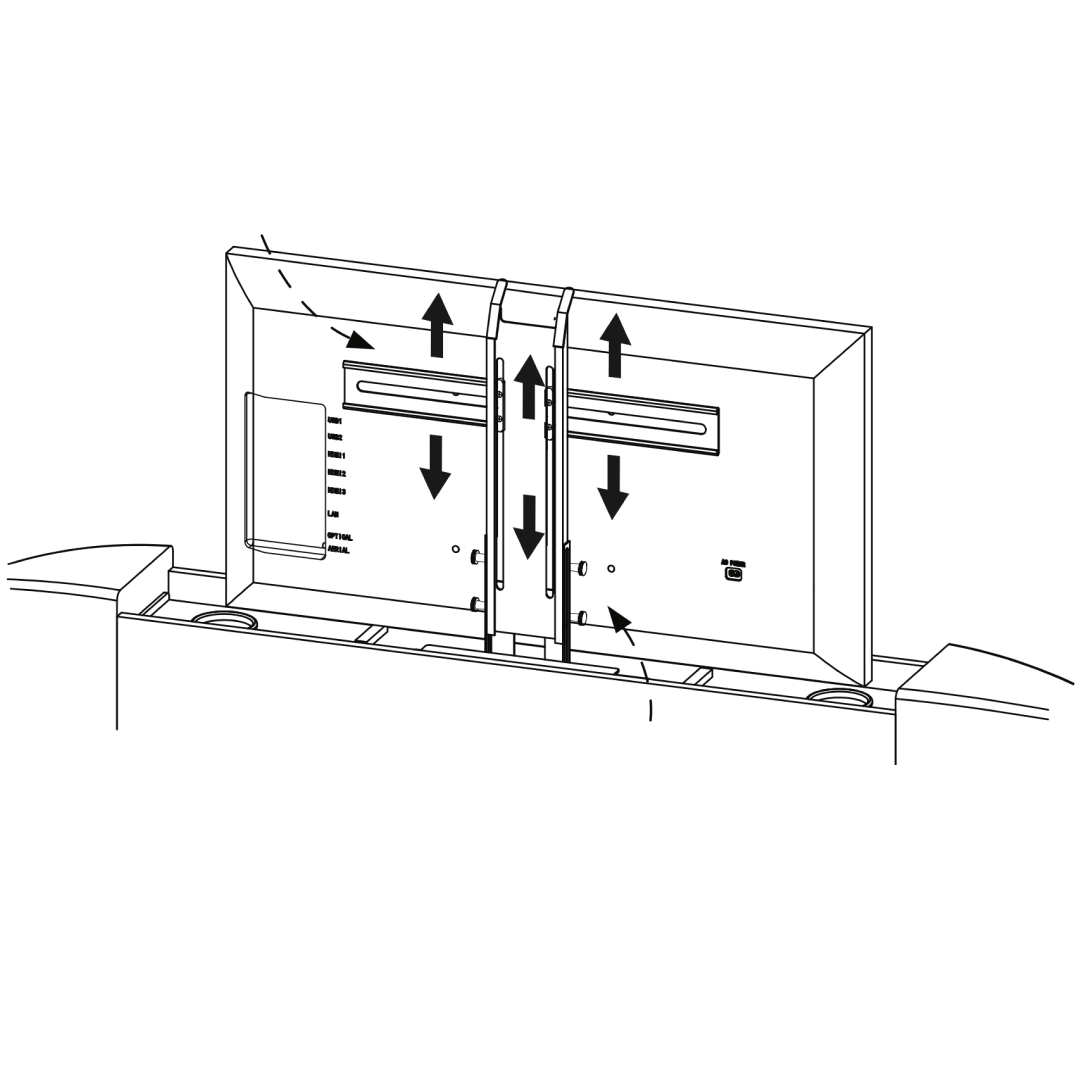
12. TV Mechanism
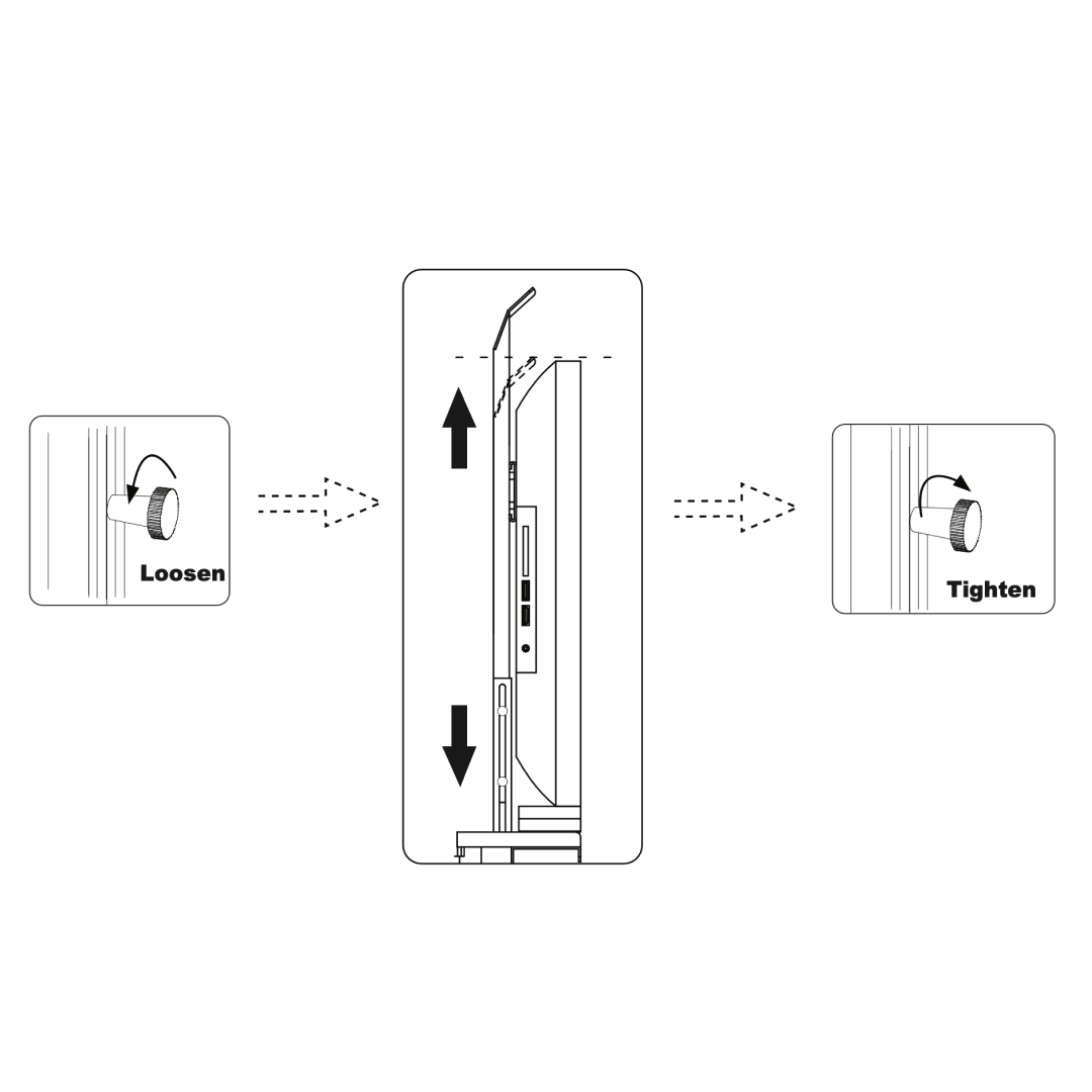
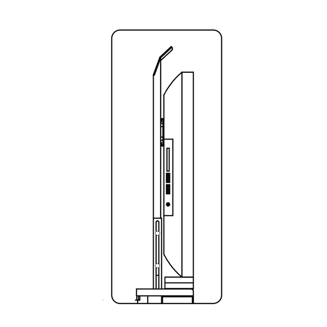
1. Secure metal brackets to the lift mechanism with screws (a). 2. Align and secure the TV to the brackets. 3. Loosen knobs, set height, then tighten. 4. Ensure smooth movement, adjust if needed.
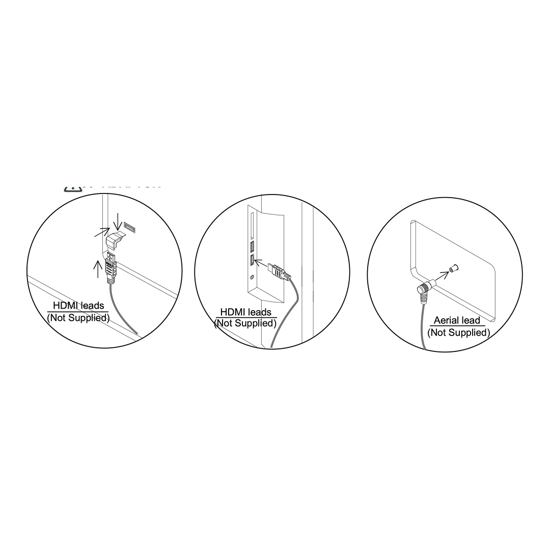
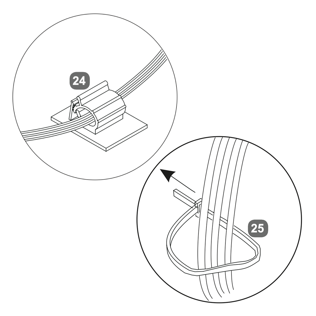
13. TV cables
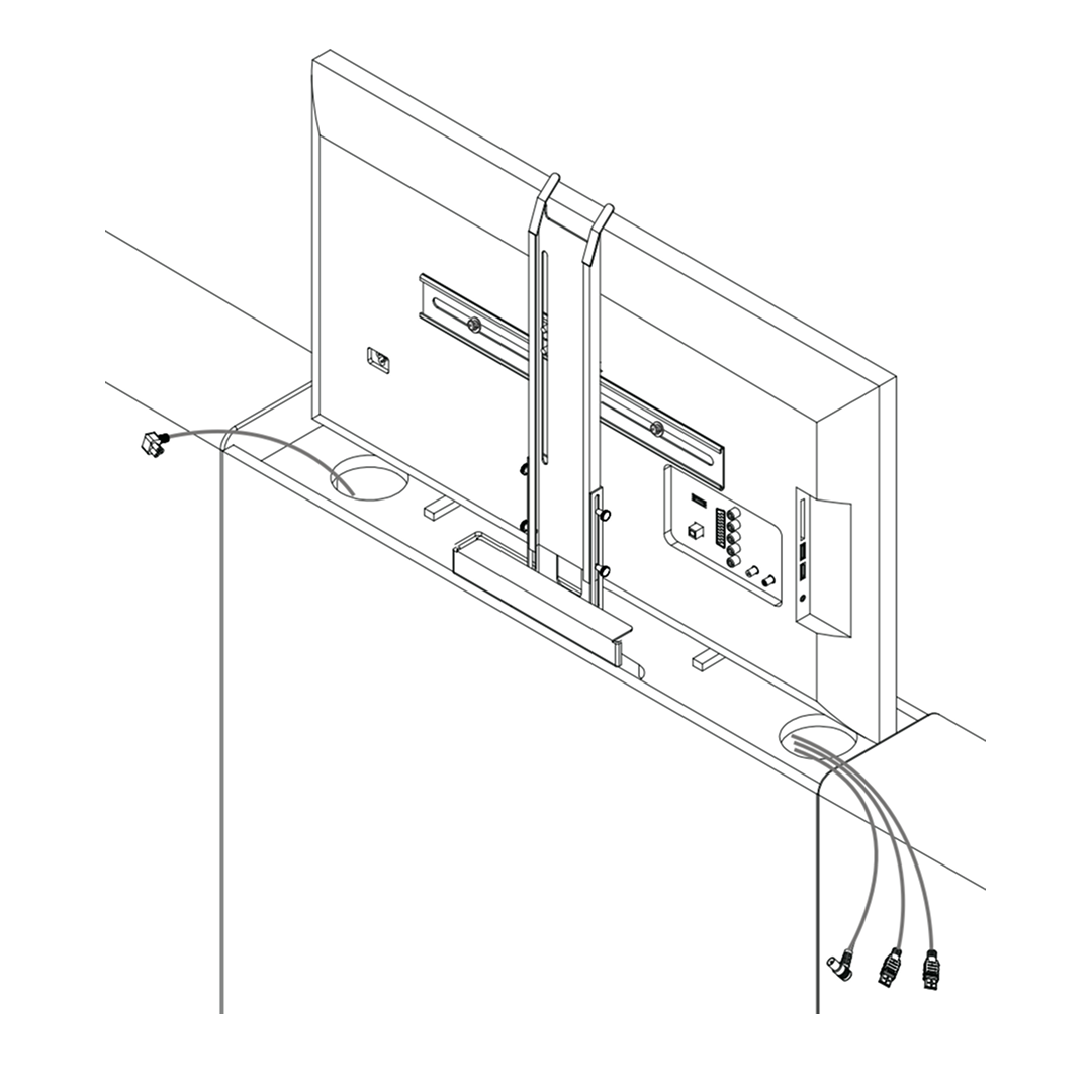
1. Insert the power cable into the designated socket on the TV lift mechanism. Ensure the connection is secure. 2. Attach HDMI leads to the TV's HDMI ports. Note that HDMI leads are not supplied. 3. Connect the aerial lead to the TV's aerial input. The aerial lead is also not supplied. 4. Use the provided cable clips to secure and organize the cables. Ensure they are neatly arranged to prevent tangling or obstruction.
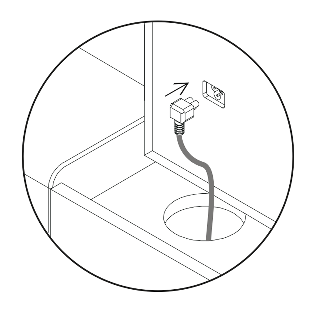
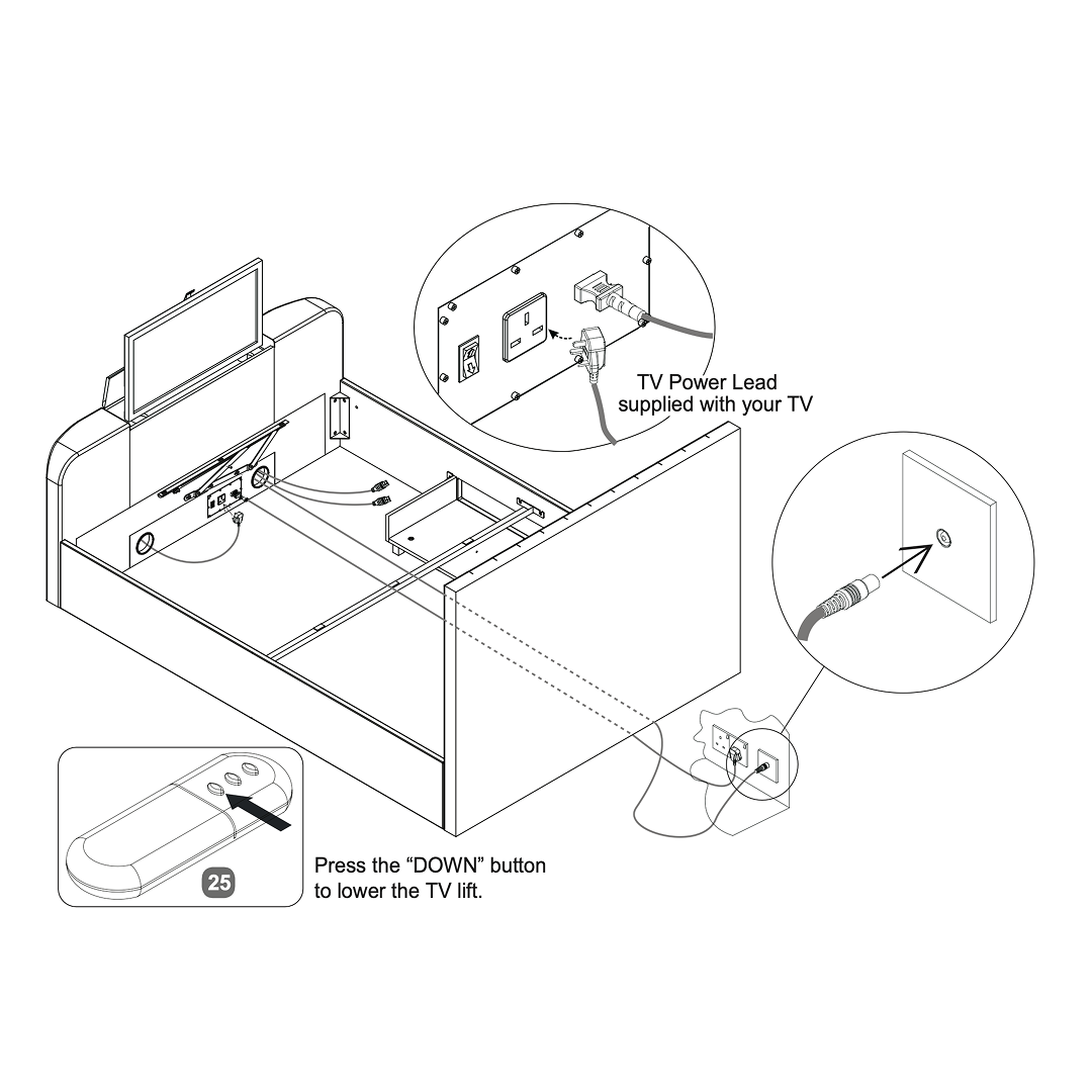
14. Connect the cables
1. Connect the TV power lead supplied with your TV to the power outlet. 2. Ensure the media cables are properly connected through the designated slots in the footboard. 3. Use the remote control to press the "DOWN" button, lowering the TV lift mechanism into the bed frame.
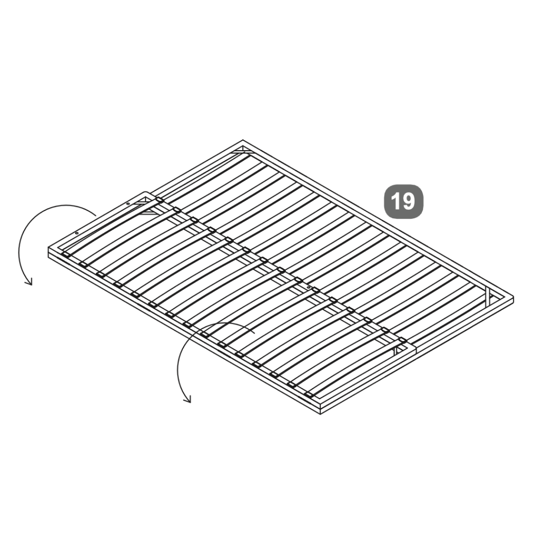
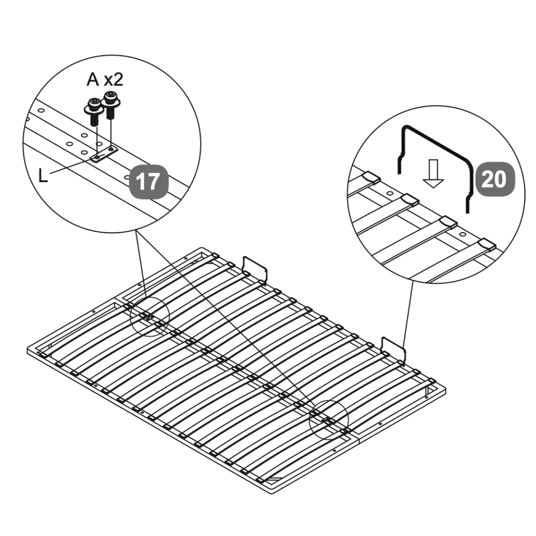
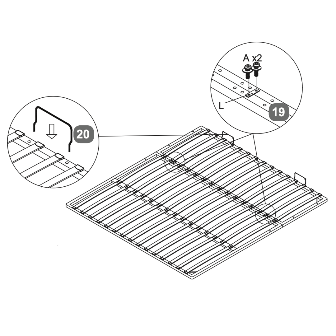
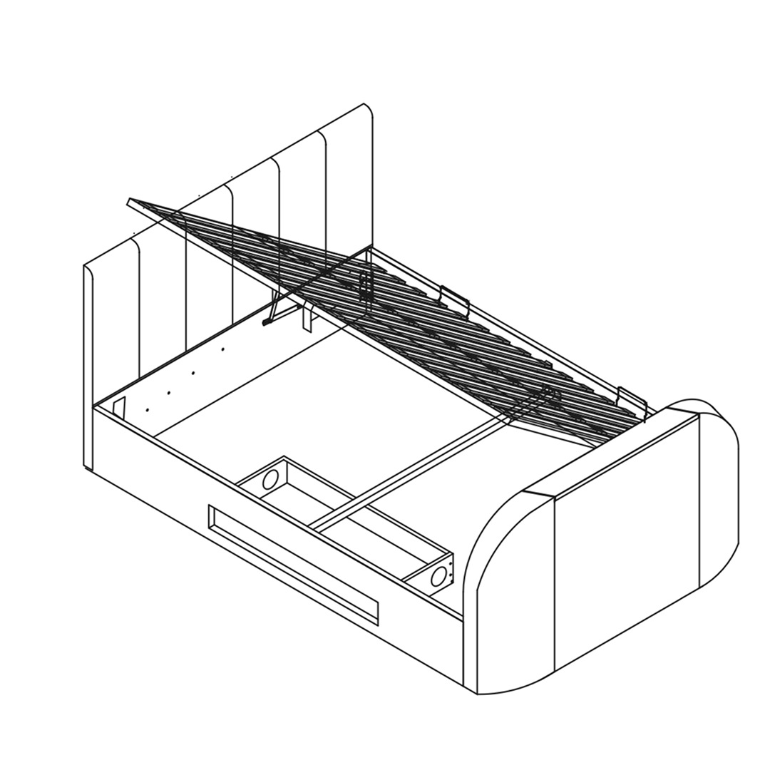
15. Slatted Base
1. Begin by laying out the slatted base as shown in the images. 2. Use the provided bolts and washers (labeled as A) to secure the slats to the frame. Insert two bolts on each side as indicated in the images. 3. Insert the support bars into the designated slots on the slatted base. 4. Verify that all components are tightly secured and aligned.
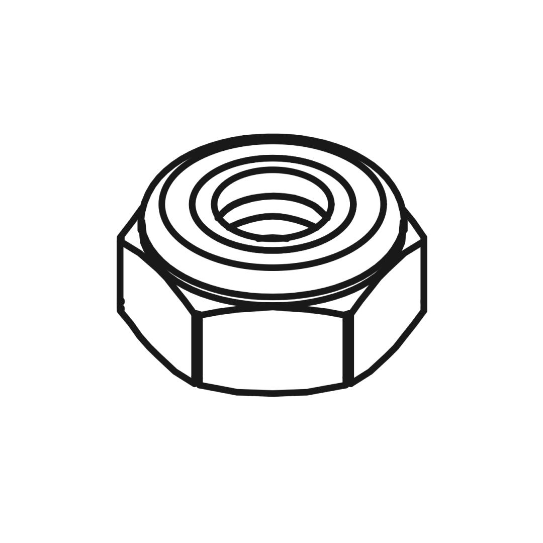
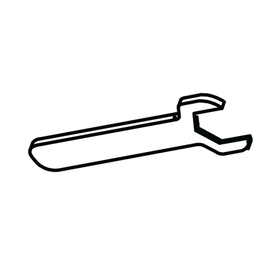
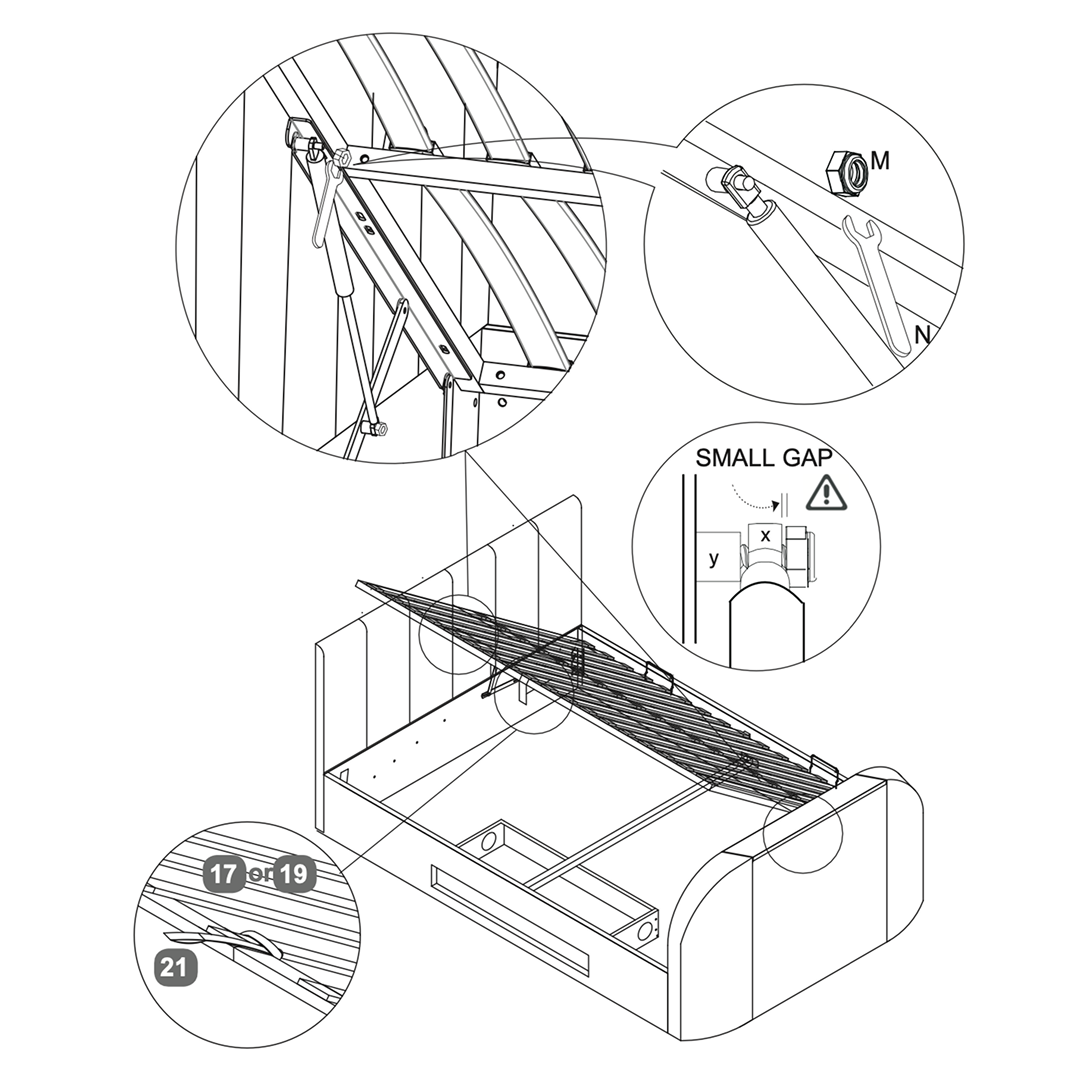
16. Slide gas-lift piston stem
1. Slide gas-lift piston stem (x) onto the axle (y) then fit the flange lock-nut (M). 2. Tighten nut with spanner (N)- do not over-tighten
A small gap must be left so stem can move freely
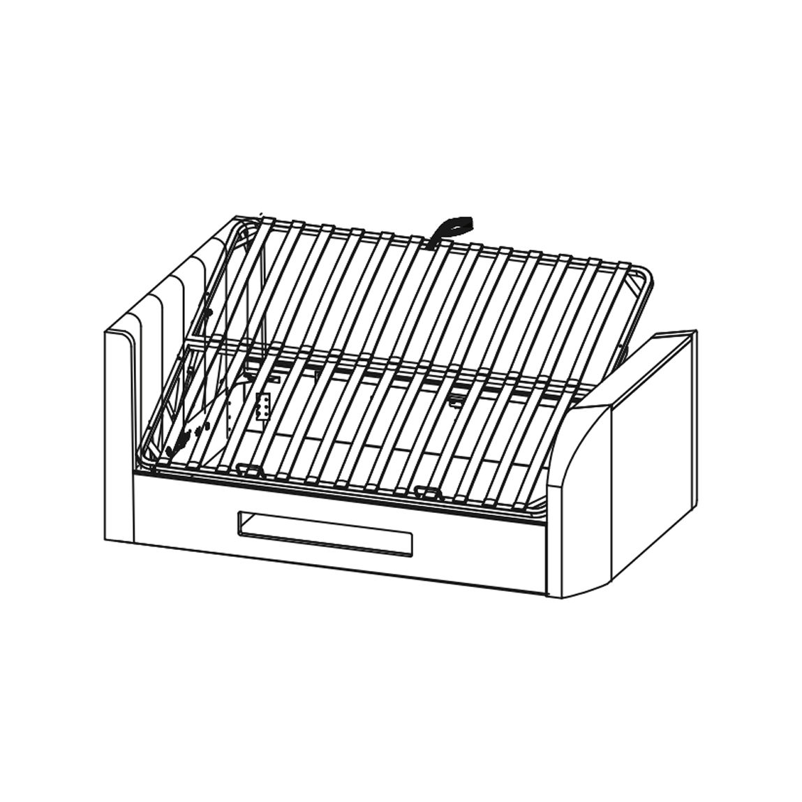
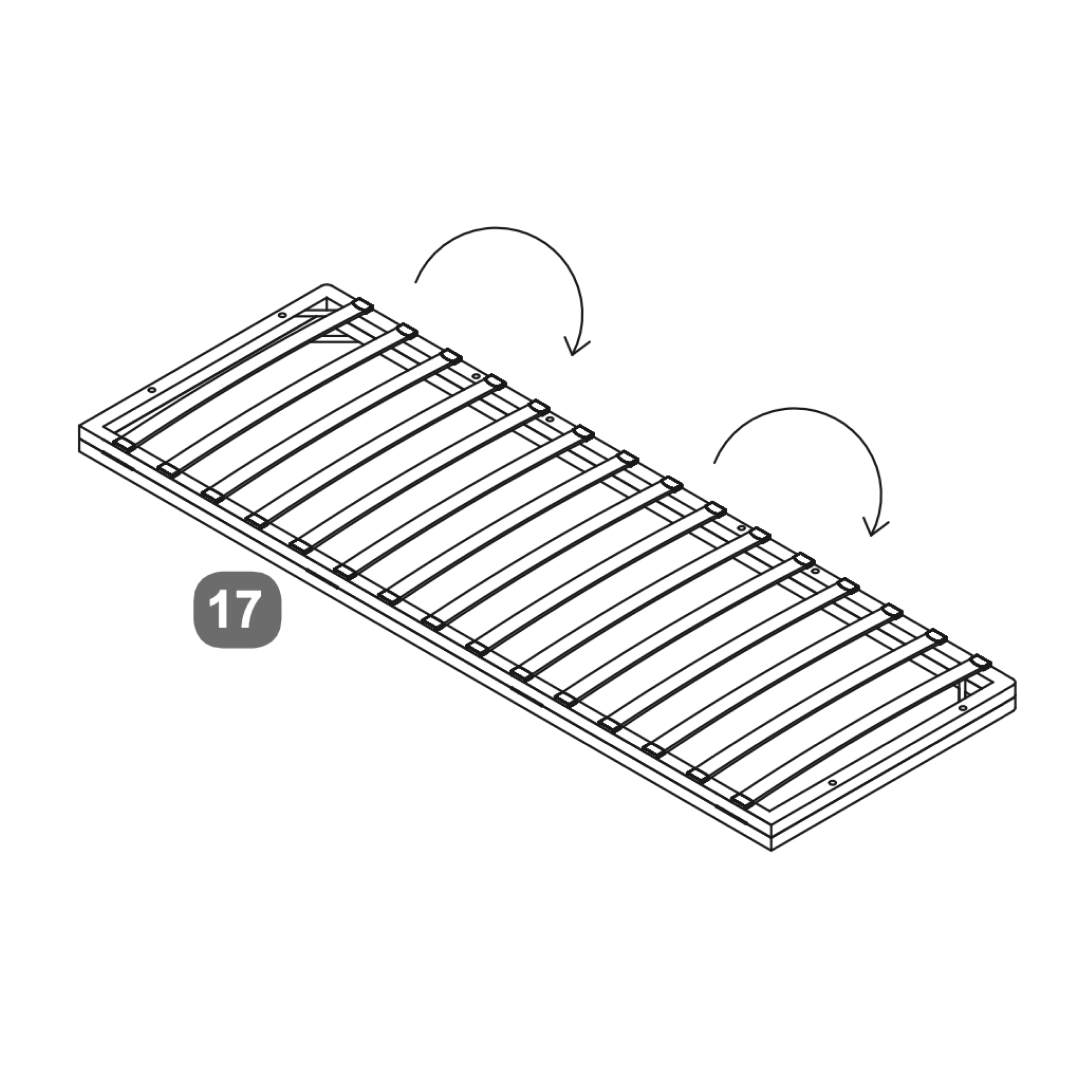
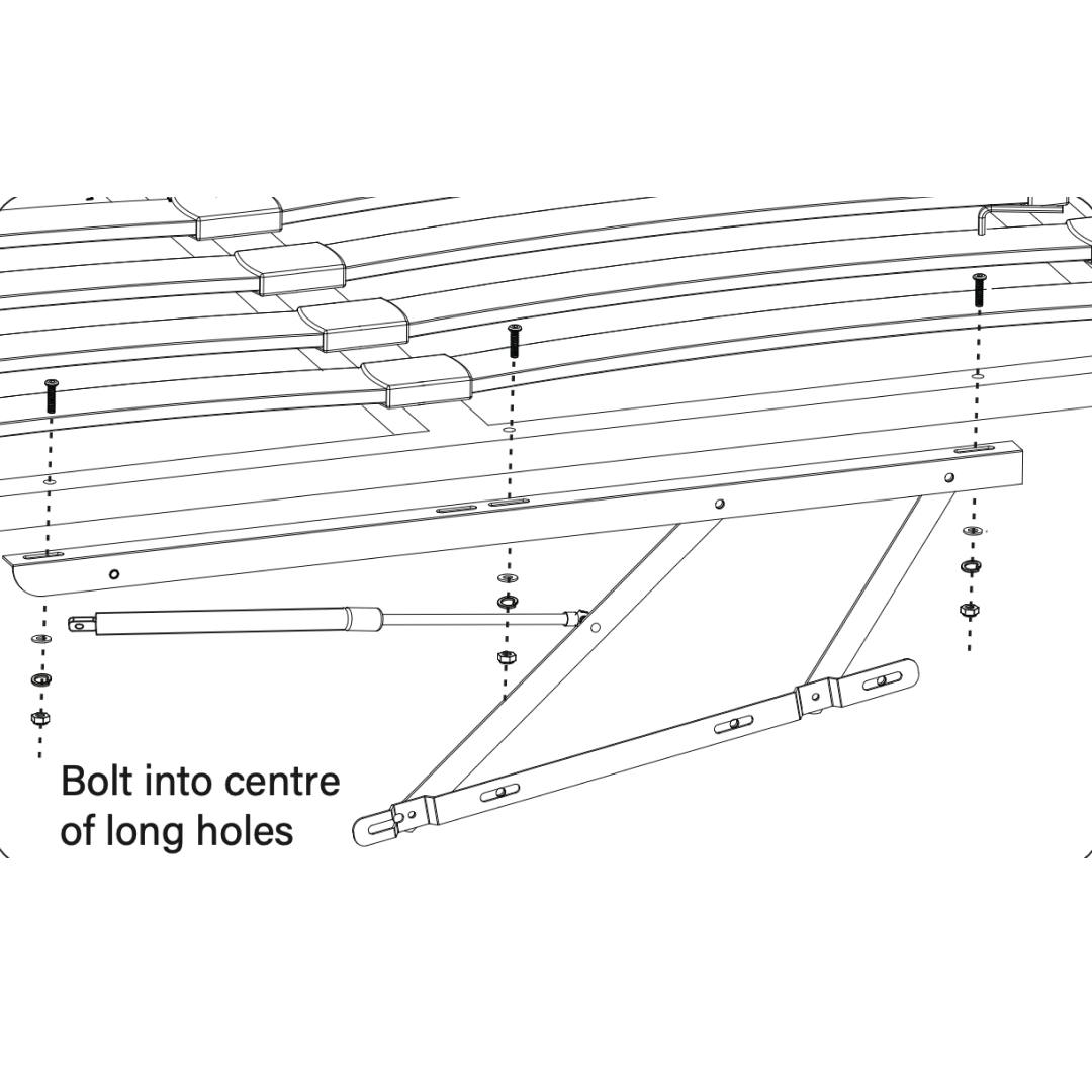
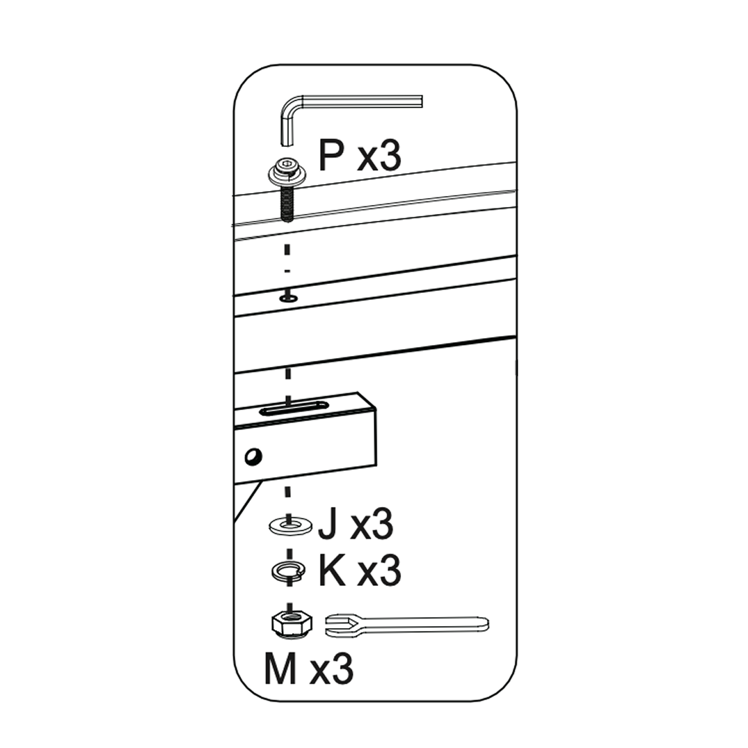
17. Attach the Slatted Base
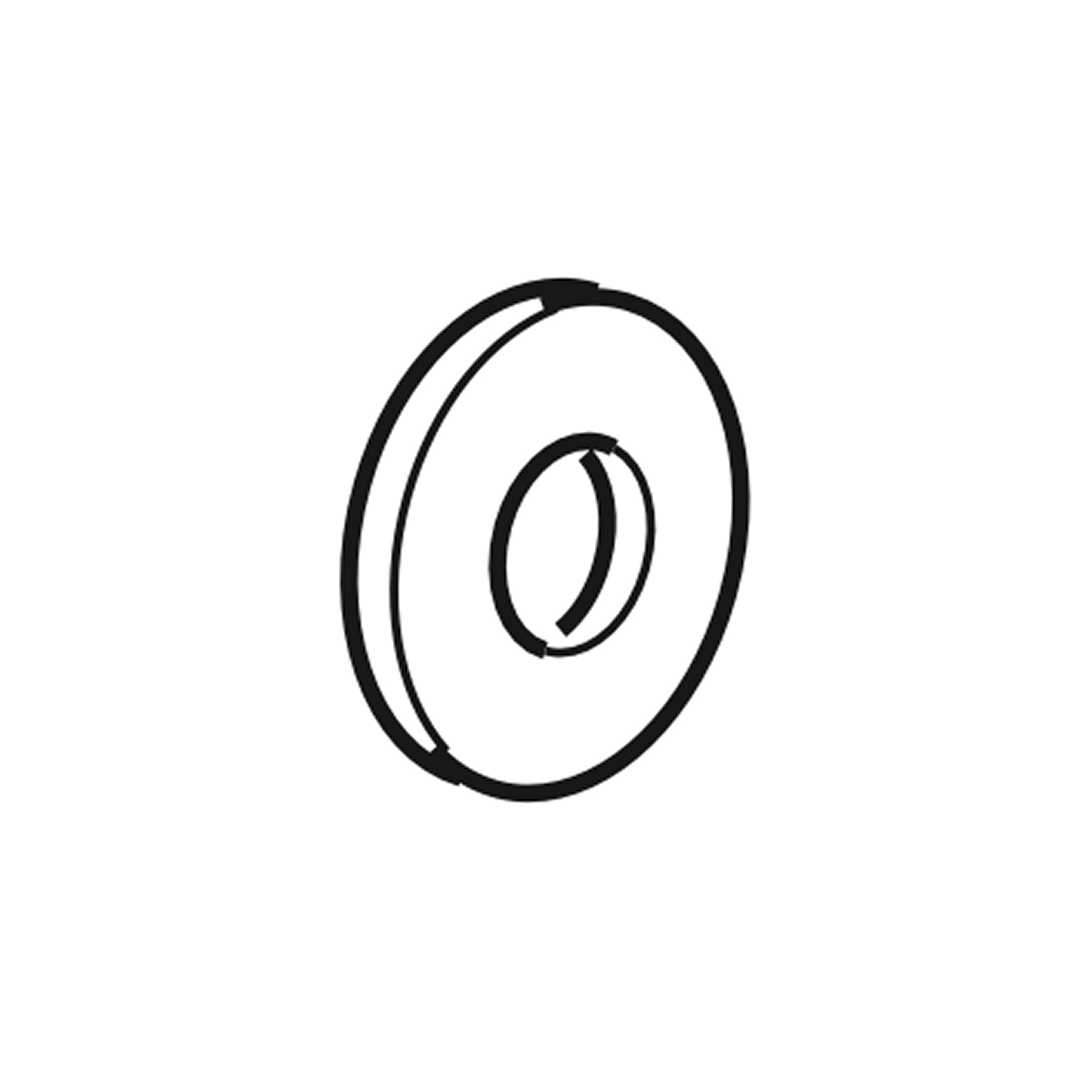
1. Position the slatted base over the bed frame, ensuring it is centered and aligned properly. 2. Use bolts (P) to secure the slats to the frame. Insert the bolts through the designated holes in the slats and into the frame. 3. Place washers (J and K) over the bolts, followed by nuts (M). Tighten the nuts using the provided wrench to ensure the slats are firmly secured. 4. Attach the gas lift mechanism to the frame by bolting it into the center of the long holes on the support arms. Ensure the mechanism is securely fastened. 5. Gently lift the slatted base to ensure the gas lift mechanism operates smoothly and the base raises and lowers without obstruction.
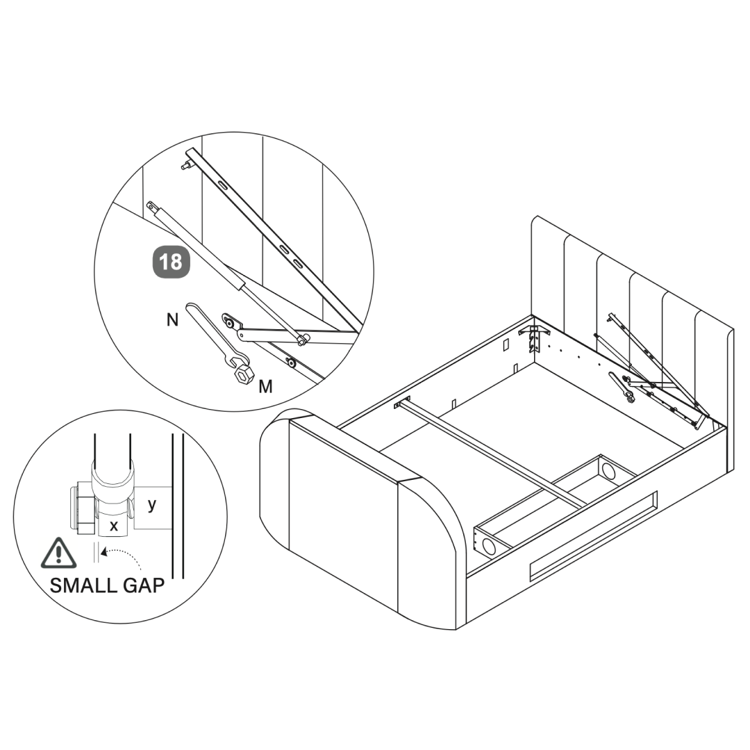
18. Attach the lift mechanism
Slide gas-lift cylinder stem (x) onto the axle (y) then fit the flange lock-nut (M). Tighten nut with spanner (N) do not over-tighten.
A small gap must be left so stem can move freely
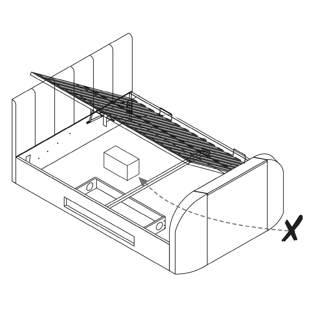
19. Safety Warnings
Please do not allow children or pets inside the storage area.
Please be careful when lifting.
Only lift with mattress on top.
To be operated by adults only.
Only use the handle to lift & lower the bed frame to avoid trapping fingers!
To avoid accidents
To access the storage area the Ottoman frame must be fully opened and then fully closed afterwards
Be very careful what you store under the bed - the top of an item, like a suitcase or a box, must not touch the slats or they may be damaged.