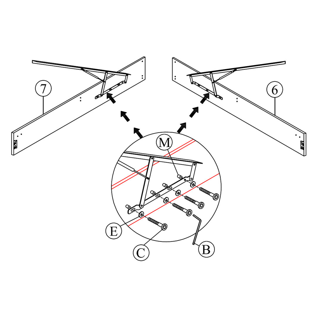


1. Attach Gas Lift Machines to Lift Frames
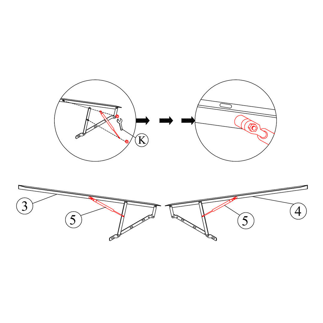
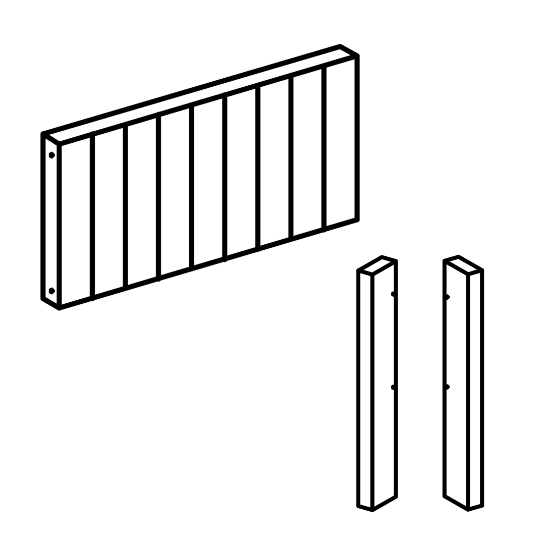
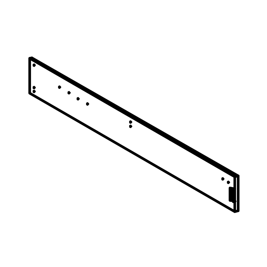
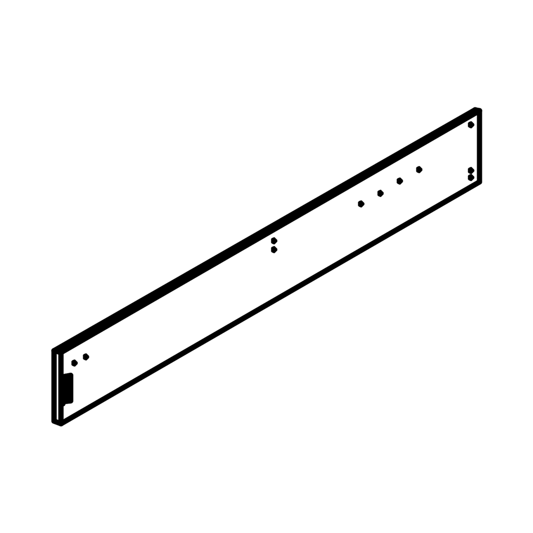
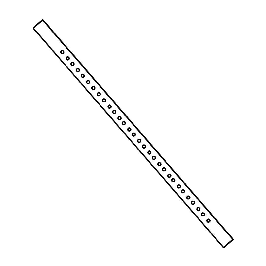
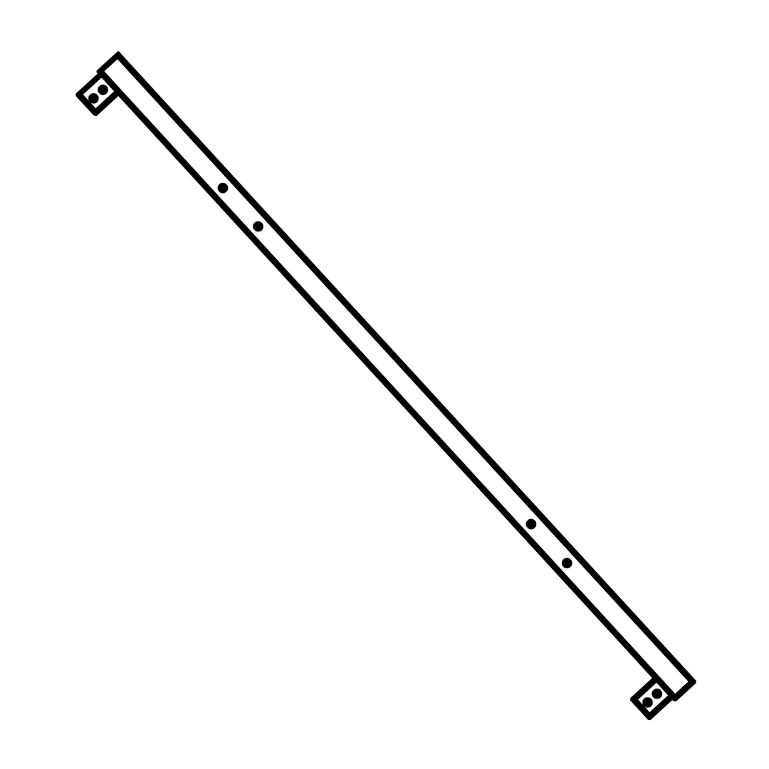
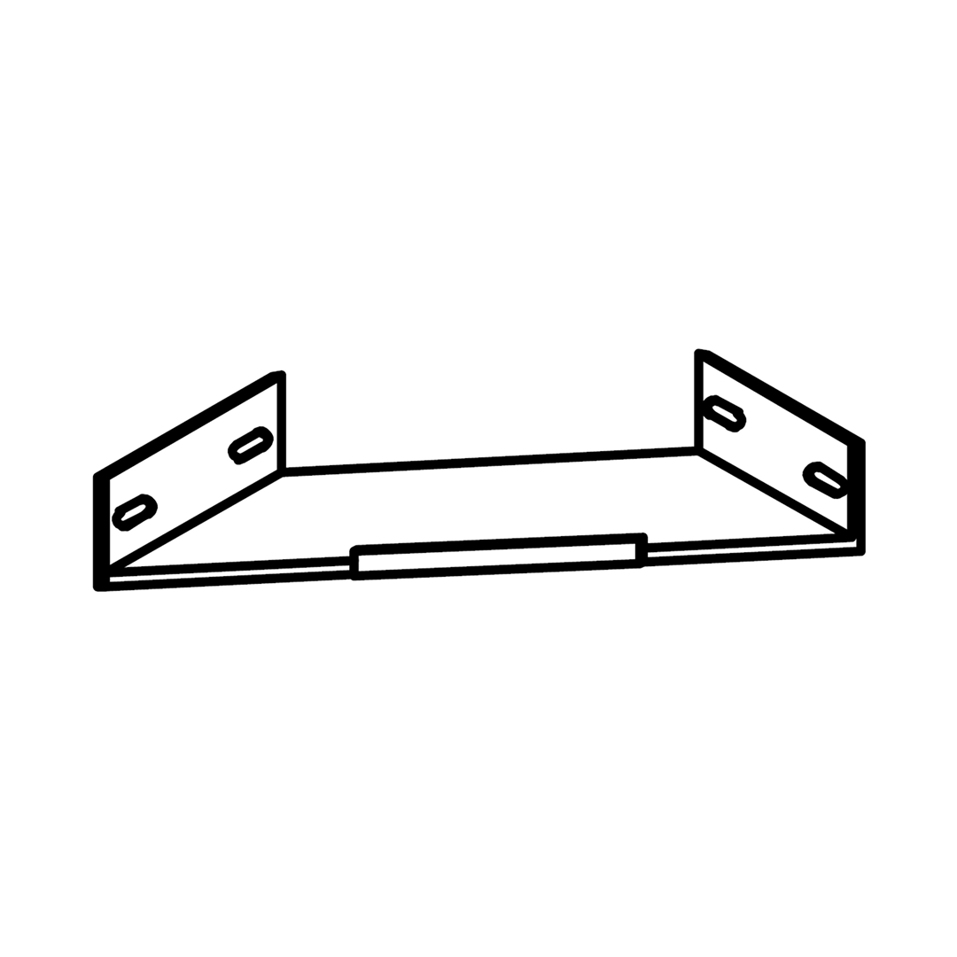
1. Position the Left Gas Lift Frame (3) and Right Gas Lift Frame (4) on a flat surface.
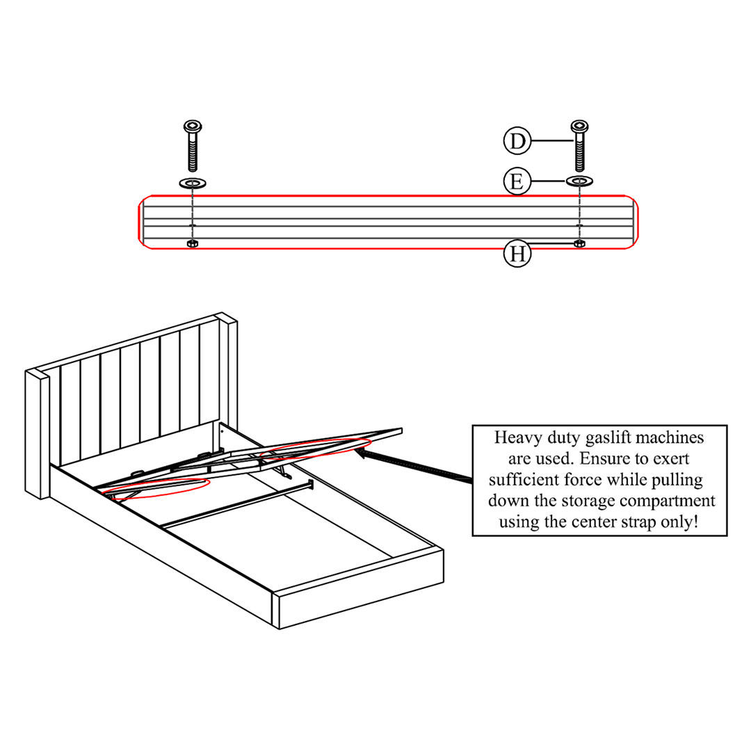
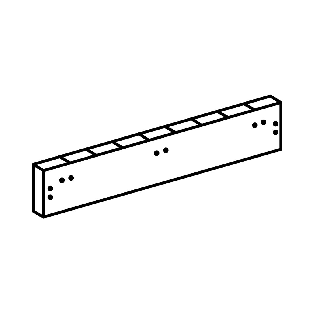
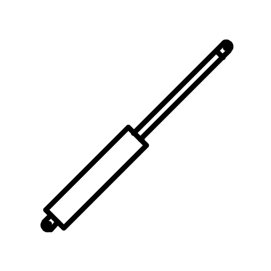
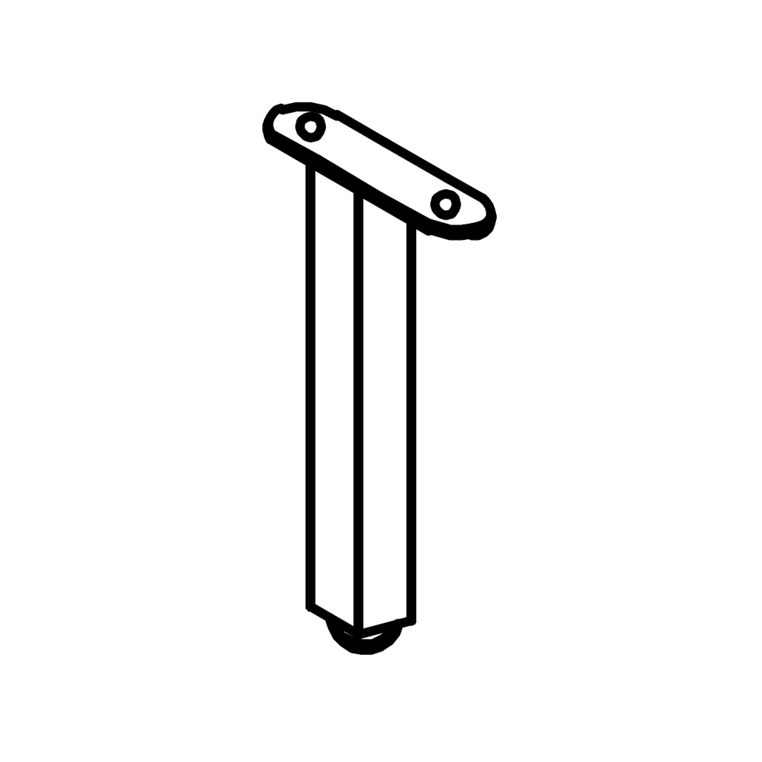
2. Align the holes on each frame with the Gas Lift Machine (5).
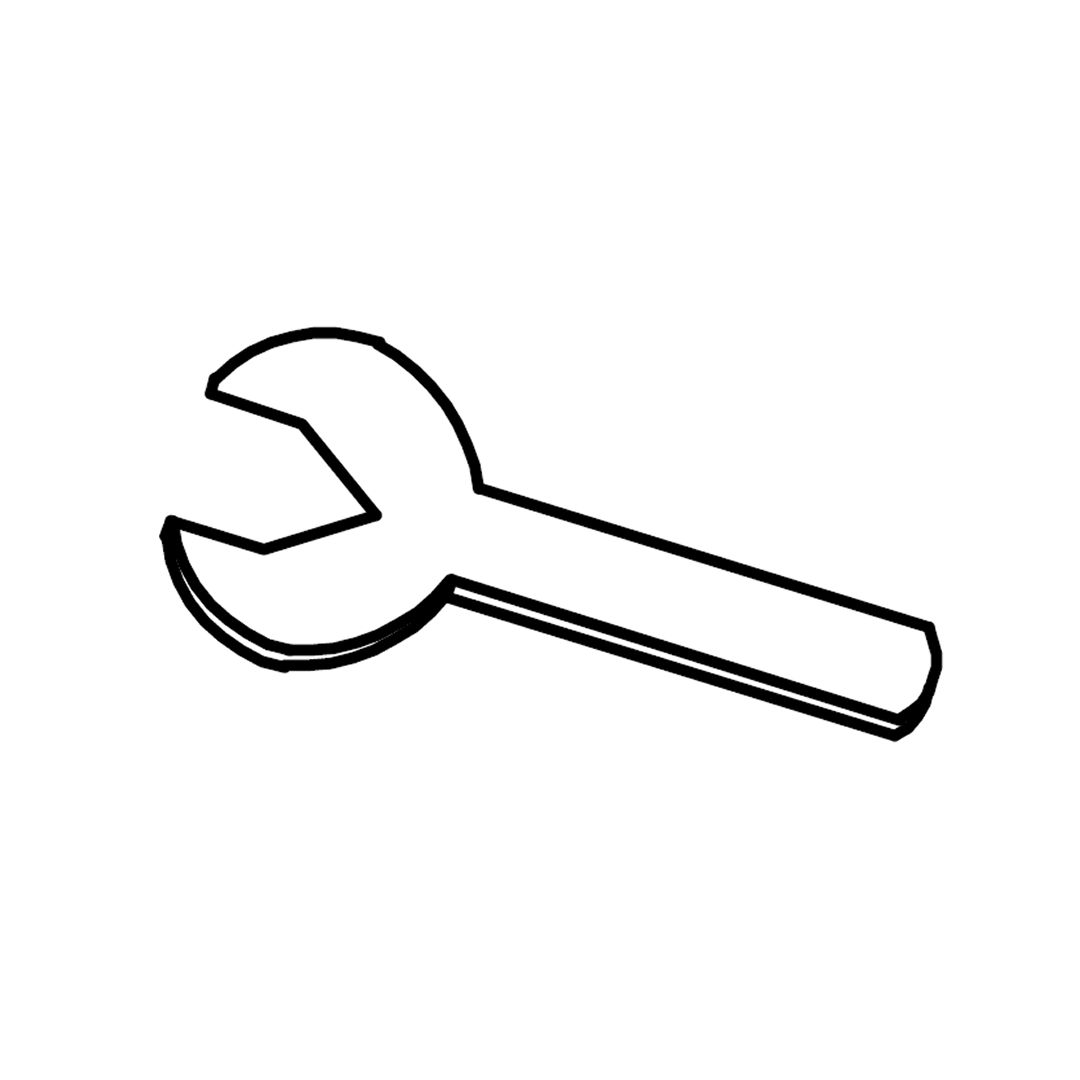
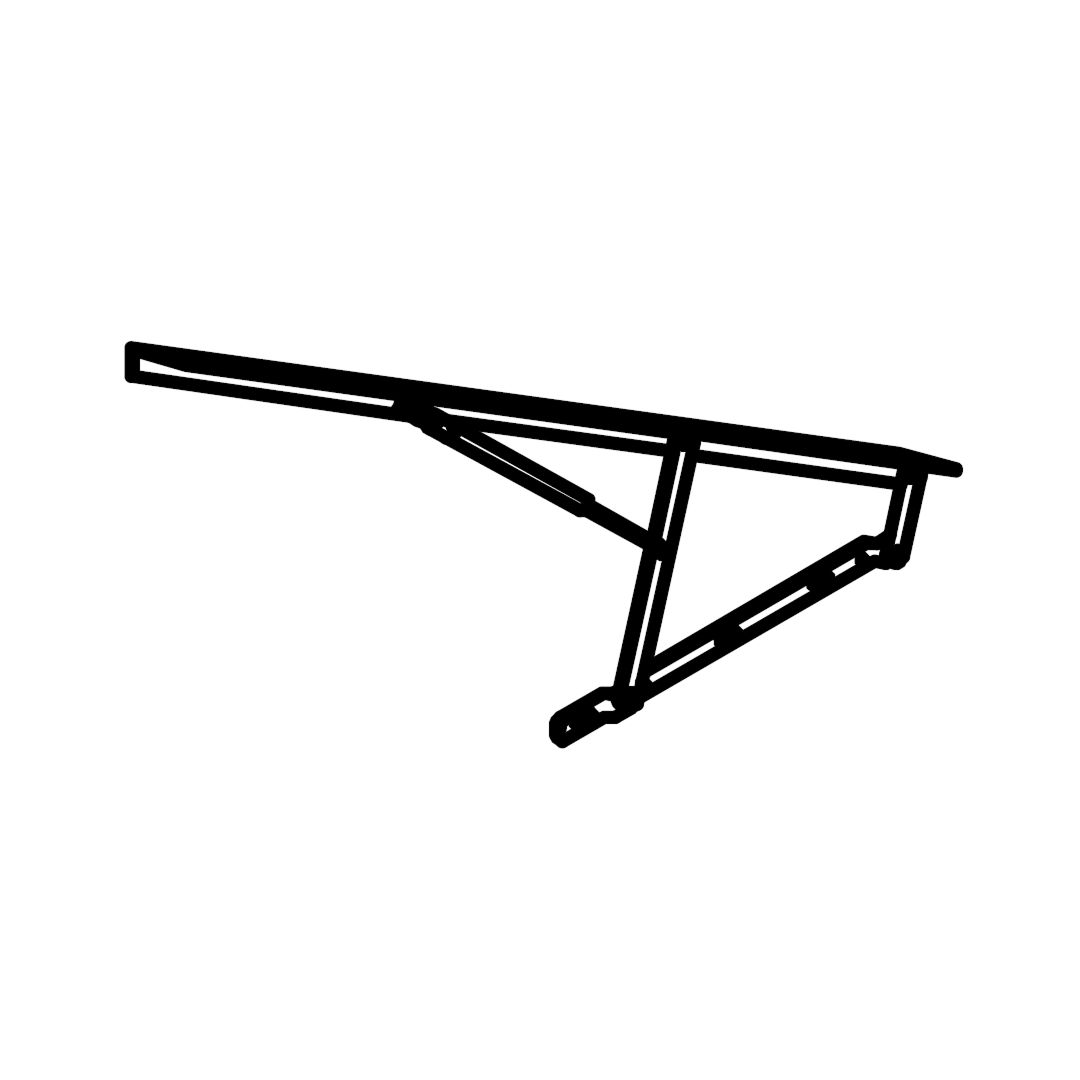
3. Using the M8 Spanner (K), secure the Gas Lift Machines to the Lift Frames with the pre-attached bolts and nuts (already included on the Gas Lift Machine).
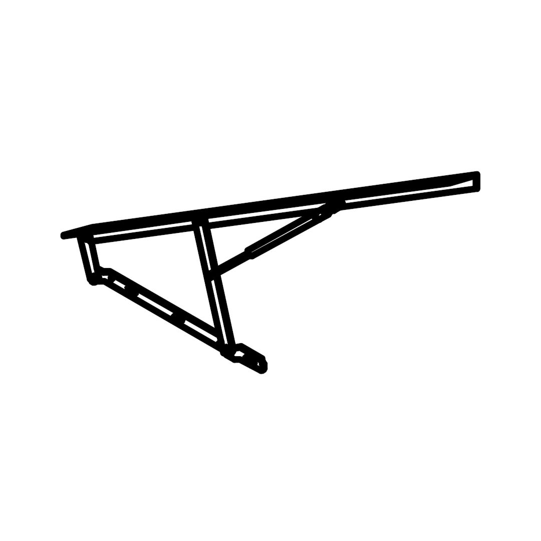
4. Ensure both sides are firmly attached and the piston arms move smoothly when lifted.
Tip: Don’t over-tighten the bolts. The arms should move with controlled resistance, not stiffness.